EP0671145B1 - Capteur pour un lit et lit comprenant un capteur - Google Patents
Capteur pour un lit et lit comprenant un capteur Download PDFInfo
- Publication number
- EP0671145B1 EP0671145B1 EP95301312A EP95301312A EP0671145B1 EP 0671145 B1 EP0671145 B1 EP 0671145B1 EP 95301312 A EP95301312 A EP 95301312A EP 95301312 A EP95301312 A EP 95301312A EP 0671145 B1 EP0671145 B1 EP 0671145B1
- Authority
- EP
- European Patent Office
- Prior art keywords
- bed
- sensing device
- occupant
- sensor
- weight
- Prior art date
- Legal status (The legal status is an assumption and is not a legal conclusion. Google has not performed a legal analysis and makes no representation as to the accuracy of the status listed.)
- Expired - Lifetime
Links
- 238000012544 monitoring process Methods 0.000 claims abstract description 18
- 239000002184 metal Substances 0.000 claims description 6
- 230000002452 interceptive effect Effects 0.000 claims description 3
- 230000000284 resting effect Effects 0.000 claims description 2
- 230000005355 Hall effect Effects 0.000 abstract description 5
- 235000014676 Phragmites communis Nutrition 0.000 abstract description 3
- 229910000831 Steel Inorganic materials 0.000 abstract description 3
- 230000004044 response Effects 0.000 abstract description 3
- 239000010959 steel Substances 0.000 abstract description 3
- 206010038743 Restlessness Diseases 0.000 description 5
- 208000001431 Psychomotor Agitation Diseases 0.000 description 3
- 238000001514 detection method Methods 0.000 description 3
- 210000002414 leg Anatomy 0.000 description 3
- 239000000463 material Substances 0.000 description 3
- 230000009471 action Effects 0.000 description 2
- 210000001217 buttock Anatomy 0.000 description 2
- 230000008859 change Effects 0.000 description 2
- 238000012986 modification Methods 0.000 description 2
- 230000004048 modification Effects 0.000 description 2
- 239000004065 semiconductor Substances 0.000 description 2
- 125000006850 spacer group Chemical group 0.000 description 2
- 208000035657 Abasia Diseases 0.000 description 1
- 208000004210 Pressure Ulcer Diseases 0.000 description 1
- 238000013459 approach Methods 0.000 description 1
- 230000008901 benefit Effects 0.000 description 1
- 230000005540 biological transmission Effects 0.000 description 1
- 230000006835 compression Effects 0.000 description 1
- 238000007906 compression Methods 0.000 description 1
- 230000009429 distress Effects 0.000 description 1
- 229940079593 drug Drugs 0.000 description 1
- 239000003814 drug Substances 0.000 description 1
- 230000000694 effects Effects 0.000 description 1
- 210000003414 extremity Anatomy 0.000 description 1
- 239000006260 foam Substances 0.000 description 1
- 238000007689 inspection Methods 0.000 description 1
- 238000002955 isolation Methods 0.000 description 1
- 206010025482 malaise Diseases 0.000 description 1
- 238000004519 manufacturing process Methods 0.000 description 1
- 238000000034 method Methods 0.000 description 1
- 238000012806 monitoring device Methods 0.000 description 1
- 230000002035 prolonged effect Effects 0.000 description 1
- 230000035882 stress Effects 0.000 description 1
- 230000001960 triggered effect Effects 0.000 description 1
Images



Classifications
-
- A—HUMAN NECESSITIES
- A61—MEDICAL OR VETERINARY SCIENCE; HYGIENE
- A61B—DIAGNOSIS; SURGERY; IDENTIFICATION
- A61B5/00—Measuring for diagnostic purposes; Identification of persons
- A61B5/103—Measuring devices for testing the shape, pattern, colour, size or movement of the body or parts thereof, for diagnostic purposes
- A61B5/11—Measuring movement of the entire body or parts thereof, e.g. head or hand tremor or mobility of a limb
-
- A—HUMAN NECESSITIES
- A61—MEDICAL OR VETERINARY SCIENCE; HYGIENE
- A61B—DIAGNOSIS; SURGERY; IDENTIFICATION
- A61B5/00—Measuring for diagnostic purposes; Identification of persons
- A61B5/68—Arrangements of detecting, measuring or recording means, e.g. sensors, in relation to patient
- A61B5/6887—Arrangements of detecting, measuring or recording means, e.g. sensors, in relation to patient mounted on external non-worn devices, e.g. non-medical devices
- A61B5/6892—Mats
-
- A—HUMAN NECESSITIES
- A61—MEDICAL OR VETERINARY SCIENCE; HYGIENE
- A61B—DIAGNOSIS; SURGERY; IDENTIFICATION
- A61B5/00—Measuring for diagnostic purposes; Identification of persons
- A61B5/68—Arrangements of detecting, measuring or recording means, e.g. sensors, in relation to patient
- A61B5/6887—Arrangements of detecting, measuring or recording means, e.g. sensors, in relation to patient mounted on external non-worn devices, e.g. non-medical devices
- A61B5/6891—Furniture
-
- A—HUMAN NECESSITIES
- A61—MEDICAL OR VETERINARY SCIENCE; HYGIENE
- A61B—DIAGNOSIS; SURGERY; IDENTIFICATION
- A61B5/00—Measuring for diagnostic purposes; Identification of persons
- A61B5/74—Details of notification to user or communication with user or patient; User input means
- A61B5/7405—Details of notification to user or communication with user or patient; User input means using sound
Definitions
- This invention relates to sensing devices arrangements, and in particular relates to sensing devices for beds which are for use mainly by persons who are unwell or infirm, and who require monitoring because of their condition.
- the invention also relates to beds with sensing devices.
- the sensing device has particular application to beds having occupants to be monitored, it is to be mentioned that the sensing device can also be extended to items which may not strictly be termed beds, and such items include sofas and chairs, as long as such items are adapted to receive persons who are to be monitored.
- a weight responsive switching device in the form of a flexible and elongate sensor consisting of two flexible sheets cemented with electrically conductive layers, the conductive layers being spaced apart by an electrically insulating foam support frame.
- the sensor is placed across a mattress and a patient lies over the sensor to create electrical contact between the conductive layers. If a patient leaves or falls from the bed, the contact is broken and an alarm may be sounded to indicate a state of danger to the patient.
- the device is relatively fragile and is essentially a disposable item, requiring replacement on a monthly basis due to wear and tear.
- a pressure operated, spring loaded electrical switch and an alarm system are provided, and the switch is located at the base of a leg of a hospital bed, so that when the bed is occupied, the weight of the occupant loads the switch to keep same open, but when the patient leaves the bed, the switch is closed by spring action, and the alarm is operated.
- the various detection and monitoring devices may be associated with alarms to signal critical condition.
- a sensing device adapted in use to be supported by the support frame of the bed for monitoring an occupant of a bed, the sensing device comprising a substantially planar lower member, a substantially planar upper member which flexes downwards under the weight of the occupant and is mounted in a thinly spaced and generally parallel relation with the lower member, and a sensor means located between the upper member and the lower member so that the sensor means is pressed as a result of the upper member being flexed downwards under the weight of the occupant to produce a signal showing the presence of the occupant resting on the bed characterised in that said sensor means is at least one point sensor which responds to downward flexing of the upper member and said upper member (4, 118) is rigid and is arranged to flex downwards under the weight of the occupant of the bed to press the sensor even if the weight of the occupant is applied to the upper member in a position offset from the location of the sensor.
- the system also provides a means of indicating movement of a patient in bed.
- This arrangement provides for a sensing device which is able to monitor pressure exerted over a wide area on a bed whilst using a simple and effective point sensor arrangement.
- the device is preferably adapted for use between the mattress and support frame of a bed.
- the lower member is preferably substantially rigid, which allows the sensing device to be placed on various types of support frames without affecting the operation of the device.
- the support frame may be a plate or a meshwork metal grille.
- the upper and/or the lower members are preferably metal plates, and are preferably of between 1mm and 5mm in thickness.
- the thickness of the plates is preferably 2mm.
- the upper and lower members are preferably spaced by less than 5cm, and are further preferably spaced at around 1 cm apart, which provides for a compact and unobtrusive sensing unit.
- the said members are preferably at least 20cm wide.
- the said sensor is preferably mounted centrally in the sensing device.
- the upper and lower plates are preferably spaced by rigid mounting means located at opposed ends of the sensing unit, the sensor being located centrally of the said opposed ends.
- the said mounting means preferably comprise two parallel spaced bars, the said members being generally unsupported between the bars.
- the weight of an occupant on the sensing unit will cause the upper member to flex downwards.
- the upper member will flex upwards which movement is sensed by the sensor positioned between the plates.
- the sensing unit is preferably coupled to an alarm indicator which is activated when an occupant leaves the bed in which the sensing unit is placed.
- the alarm may be an audible alarm so as to alert a nurse or other helper in the immediate vicinity.
- the unit may be connectable to the Nurse-Call systems operating in Hospitals so that the occupancy of a number of beds can be monitored by a single nurse at the Nurse-Call control desk.
- the sensing unit is preferably coupled to a control unit responsive to the sensing unit which is provided with a light alarm such as a brightly flashing LED, the control unit being adapted to be mounted in a visible position on a bed. This provides for ready identification of a bed from which an occupant has departed or fallen.
- the sensing unit may be used to indicate when a patient approaches the periphery of the bed and is therefore in danger of falling from the bed.
- the sensor may be a micro-switch.
- the sensor preferably is of the type having two interactive parts, one part being mounted on each plate.
- the sensor may consist of a reed switch located on one member and a magnet on the other member.
- the sensor may consist of a Hall effect semiconductor device located on one member and a magnet on the other member.
- the senor is a linear output transducer such as a linear output Hall effect transducer, which allows for monitoring of lower levels of the occupants movement such as restlessness and tossing and turning.
- the transducer when measuring and excessive drop in weight above the sensor may in any case trigger an alarm as described in relation to the above switching devices.
- a restlessness monitor may also be provided by positioning two switching devices at opposed sides of the sensing unit. A patient tossing and turning from side to side will alternately activate both switches continually, which may be monitored using appropriate associated electronic circuitry.
- a bed comprising bed frame and a support sheet which will when the bed is occupied by a patient be deflected to a predetermined degree, regardless of the position of the patient in the bed, characterised by at least one point sensor, which may be simply an on-off limit switch or may be a weight responsive transducer, positioned between the bed frame and the support sheet and adapted to sense this deflection to operate a sensor means comprising a rigid substantially planar upper member.
- the sensor means may be positioned on a bed during manufacture of same or may be separately fitted on mountings attachable to the bed frame.
- a modified sensing unit 2 includes upper and lower thin but rigid steel plates 4 and 6.
- the plates 4 and 6 are each approximately 2mm thick, and are rectangular having sides 12 and 14 measuring approximately 30cm x 60cm.
- the plates are spaced approximately 10mm apart by square sectioned metal bars 8 and 10.
- the spacers 8 and 10 are located in parallel relation along the periphery of the plates at the shorter ends of the plates 4 and 6.
- the sides of the plate are unsupported, allowing for flexing of the substantially rigid upper plate 4 to a shallow U-shaped section across its entire width.
- a point sensor 16 is located between the plates, centrally of the spacer bars 8 and 10 and preferably in the geometric centre thereof, such that the sensor 16 senses vertical movement of the centre of the upper steel sheet or plate 4. Signals from the sensor 16 are sent to a control unit (shown in Fig. 2) via sensor cable 18.
- the sensor unit 2 is designed to be placed on a bed base 20, below a mattress 22, in a region towards the bed head 24 of the bed region below the position where the buttocks of a patient rest if the patient lies at least generally centrally of the mattress.
- the upper plate 4 of the sensor unit flexes downwards, which movement is sensed by the sensor 16.
- the sensor is appropriately set so as to sense such a degree of movement of the upper plate 4 as is produced by the weight of a person, and also preferably is sensitive at least to the weight of a small or light person of 50-60 kg.
- the control unit is provided with an audible alarm (not shown), a brightly flashing LED 30 and may also be provided with a lead 28 connecting the control unit to a patient port of the Nurse-Call system in a Hospital or Care Home.
- the control unit 26 may furthermore be linked by radio wave transmission with portable receivers carried by caring staff. These receivers also alert the caring staff to a newly unoccupied bed, providing information as to the location of the bed on alert.
- the sensing unit 2 having upper and lower housing sheets 4 and 6 protecting and operating the sensor 16 provides for a durable sensing unit 2. Furthermore, the unit is self-mounting insofar as the unit 2 is simply placed between the rigid bed base 20 and mattress 22. The sensing unit 2 may be utilised with the associated informational and alarm devices described in relation to the embodiments of Figs. 3-8 below.
- the sensor 16 may be a micro-switch. However, the sensor preferably is of the type having two interactive parts, one part being mounted on each plate.
- the sensor may consist of a reed switch located on one member and a magnet on the other member.
- the sensor may consist of a Hall effect semiconductor device located on one member and a magnet on the other member.
- the micro-switch may be attached to the base of lower plate 6 with a portion projecting through an orifice in that plate so as to abut against the upper plate 4.
- This arrangement is particularly suitable where the bed base 20 consists of a metal meshwork supported on a frame. The exposed part of the sensor may then be placed between the meshwork when the sensing unit is placed on the bed base.
- the sensor 16 may also be of the type giving a linear response, such as a linear output Hall Effect transducer which may be utilised to monitor lower levels of movement of the bed occupant. Restlessness could be charted by a recording device for inspection at a later time, for the purposes of assessing the need for medication or other attention. Should the patient leave the bed, the same device would trigger the alarm system via control unit 26.
- a linear output Hall Effect transducer which may be utilised to monitor lower levels of movement of the bed occupant. Restlessness could be charted by a recording device for inspection at a later time, for the purposes of assessing the need for medication or other attention. Should the patient leave the bed, the same device would trigger the alarm system via control unit 26.
- the control unit 26 may also be connectable to a moisture detection device for monitoring the bed sheets of a patient lacking bowel control.
- the alarm system would be triggered on the detection of moisture to allow a nurse to rectify the matter, which would increase the overall level of comfort of the patient and reduce the incidence of bed sores.
- FIG. 3 shows a standard hospital bed 110 comprising a frame 112 standing on legs 114.
- the frame 112 has one or more cross bars 116 extending between the longer sides, and normally the frame is covered by means of a metallic sheet 118 of the same rectangular configuration as the frame, and sheet 118 is lightly ribbed as shown at 120 to improve its rigidity.
- the sheet 118 is normally pop-riveted to the frame 112 which is made up of hollow rectangular sectioned bars. When such a bed is occupied by a patient, it flexes and/or is strained to such a degree that use can be made of the deflection and/or straining of the bed to provide a very simple and effective means of monitoring patient pressure or movement in the bed.
- a micro-switch sensor 124 having an operating button 126 is positioned on the centre of the cross bar 116 which is shown in Fig. 3, and which lies in the vicinity of the bed occupant's buttocks when the bed is properly occupied, and the micro switch is located in an aperture 126 in the sheet 122.
- the bed may have a junction control box 127 which is releasably clamped to the bottom of the bed frame where it cannot be reached by the patient.
- the box 127 may have an on/off isolation switch, a battery to power the system, a battery rundown warning light and an audible alarm to respond locally to the bed occupants' movements.
- the box is electrically coupled to the micro switch to isolate it, and the box may have an on/off warning light.
- the arrangement shown in Fig. 4 is when the bed is not occupied, but when it is occupied, the sheet 118 will deflect as described herein, and as shown in Fig. 5 will compress the rubber sheet 122 in the regions 122A and 122B with the result that the deflecting sheet 118 will press button 126 of the micro switch and operate same to move it to its opposite condition.
- This condition will in fact be the monitoring condition so that when the micro switch is in the position of Fig. 5 it is closed and will break an alarm or monitoring circuit.
- the alarm or monitoring circuit is complete and a signal will be given at a remote location to a person monitoring the occupant of the bed.
- the bed when occupied by a person will result in the micro switch 124 being in the circuit breaking condition, but should the person leave the bed, the sheet 118 will return to the Fig. 4 position by virtue of its own resilience and by virtue of the re-expansion of the rubber layer 122, and an alarm will be given or sounded so that a person monitoring a patient will know immediately that he or she has left the bed. Where such patient is of such fragility and for example unable to walk, it is important that the person monitoring the patient should know as soon as he or she has left the bed.
- the bed shown in Fig. 3 shows only the basic structure of the bed and it will of course be provided with a mattress and covering sheets and the like.
- Figs. 6, 7 and 8 show modifications and/or alternative embodiments of the invention to indicate the range of applicability.
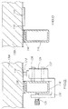
- this shows an arrangement wherein the micro switch 124 is attached to a U-shaped bracket 130 by means of a pair of screws 132, 134.
- the bracket 130 encircles the cross bar 116, and is clamped thereto by means of a clamping screw 136 which passes through the other limb of the bracket 116 and frictionally engages the wall of the cross bar 116 as shown.
- the positioning of the micro-switch is such that it will function in the same manner as described in relation to Figs. 4 and 5.
- the compressible material is in the form of a strip 138 which simply overlies the top of the cross bar 116, and it is not necessary to provide a complete sheet of the compressible material as is provided for in the case of Figs. 4 and 5.
- Fig. 6 also shows the sheet metal plate 118 and the micro-switch, operating plunger 127.
- a mattress 138A is also illustrated in this Figure, and it will be seen that it rests on plate 118.
- Fig. 7 is a sectional end view of the relevant components of the bed, the centre line of the bed is illustrated by reference 140, and again the cross bar 116 is clearly shown.
- Two micro switches 124A and 124B are symmetrically arranged to opposite sides of the centre line 140, and the bracket 130 extends along the bar 116 for a sufficient length to enable a single bracket to receive both micro switches 124A and 124B.
- the bracket 130 is clamped to the cross bar 116 in the same manner as described in relation to Fig. 6 except that two or more clamping screws 136 may be provided.
- the control box 127 which is shown in Fig. 3 and which preferably will be provided in each embodiment, is also clamped to the end rail of the bed frame by an arrangement similar to that illustrated in Fig. 6.
- An advantage of the arrangement of Fig. 7 is that as two micro switches are used and are operated with the deflection of the sheet 118, the micro switches can be used not only for indicating when a patient is out of bed, but also when a patient is restless insofar as if the patient rolls to one side of the bed, the micro switch at the other side may be caused to change condition, and there will be one micro switch "on” and another "off".
- an appropriate lamp may be used to show such a condition.
- Such a lamp may for example have a green lens so that the person monitoring the patients will know that any particular patient is moving or is restless in bed and may need attention.
- both micro switches are in the open condition, i.e. the sheet 118 is deflected upwardly, then the person monitoring the patients will know that the patient in the appropriate bed has left his or her bed and can take corrective action.
- the spacing between the micro switches 124A and 124B as shown in Fig. 7 may be in the order of 12 inches but clearly the most appropriate spacing can be selected, and the micro switches 124A and 124B are preferably adapted to be adjustably mounted along the bracket 130 in the direction of its length so that the spacing between the micro switches can be adjusted.
- an appropriate compressible strip 138 is provided between the cross bar 116 and the bed support sheet 118.
- the deflection of the sensing structure is sensed.
- sensors are used to detect the stressing of the bed structure.
- a strain gauge 144 is attached to the underside of the sheet 118 and this gauge will be stressed by virtue of stressing of the bed structure.
- the compression strip 146 may be replaced by an electronic load cell sensing the weight incident upon the plate 118 located immediately above it. The change in stress or weight indicated by the load cell or strain gauge can be used to operate the indicating means hereinbefore described.
- strain gauges or load cells can be positioned on the most appropriate locations of the bed structure.
- any of the equivalents can be utilised at the same locations or in a suitable alternative location. It is however a common feature of all sensors used that the sensors are point sensors which sense changes in spacing or weight over only a small proportion of the area over which the weight of a patient is applied.
- the invention provides cost-effective, hard wearing and reliable means for monitoring the occupant of a bed or the like.
Landscapes
- Health & Medical Sciences (AREA)
- Life Sciences & Earth Sciences (AREA)
- Surgery (AREA)
- Animal Behavior & Ethology (AREA)
- Pathology (AREA)
- Engineering & Computer Science (AREA)
- Biomedical Technology (AREA)
- Heart & Thoracic Surgery (AREA)
- Medical Informatics (AREA)
- Molecular Biology (AREA)
- Physics & Mathematics (AREA)
- Biophysics (AREA)
- General Health & Medical Sciences (AREA)
- Public Health (AREA)
- Veterinary Medicine (AREA)
- Physiology (AREA)
- Dentistry (AREA)
- Oral & Maxillofacial Surgery (AREA)
- Invalid Beds And Related Equipment (AREA)
- Measuring And Recording Apparatus For Diagnosis (AREA)
- Mattresses And Other Support Structures For Chairs And Beds (AREA)
Claims (13)
- Un capteur adapté, en utilisation, de façon à être soutenu par le cadre de support du lit, afin d'assurer le monitorage de l'occupant du lit, le capteur comprenant un élément inférieur essentiellement planaire (6, 116), un élément supérieur essentiellement planaire (4, 118) qui s'infléchit vers le bas sous le poids de l'occupant et qui est monté selon un rapport à faible intervalle et généralement parallèle avec l'élément inférieur (6, 116), et un moyen de détection (16, 124, 144) situé entre l'élément supérieur (4, 118) et l'élément inférieur (6, 116) de telle sorte que le moyen de détection (16, 124, 144) est enfoncé du fait que l'élément supérieur est infléchi vers le bas sous le poids de l'occupant afin de produire un signal indiquant la présence d'un occupant sur le lit, caractérisé en ce que ledit moyen de détection (16, 124, 144) est constitué d'un capteur ponctuel au moins (16, 124, 144) qui réagit au fléchissement descendant de l'élément supérieur (4, 118) et ledit élément supérieur (4, 118) est rigide et agencé de manière à s'infléchir vers le bas sous le poids de l'occupant du lit afin d'exercer une pression sur le capteur, même si le poids de l'occupant est appliqué sur l'élément supérieur en une position décalée par rapport à l'emplacement du capteur.
- Un capteur, selon les stipulations de la revendication 1, caractérisé en ce que l'élément inférieur (6, 116) est essentiellement rigide.
- Un capteur, selon les stipulations de la revendication 1 ou 2, caractérisé en ce que les éléments supérieurs et/ou inférieurs comportent des plaques en métal (4, 6, 116, 118).
- Un capteur, selon les stipulations de la revendication 3, caractérisé en ce que la plaque, ou les plaques, a (ont) une épaisseur située entre 1 mm et 5 mm.
- Un capteur, selon les stipulations de l'une quelconque des revendications 1 à 4, caractérisé en ce que les éléments supérieurs et inférieurs (4, 6) sont séparés l'un de l'autre par un intervalle inférieur à 5 cm.
- Un capteur, selon les stipulations de l'une quelconque des revendications 1 à 5, caractérisé en ce que lesdits éléments (4, 6) ont au moins une largeur de 20 cm.
- Un capteur, selon les stipulations de l'une quelconque des revendications 1 à 6, caractérisé en ce que ledit moyen de détection (16, 124, 144) est monté au centre du capteur.
- Un capteur, selon les stipulations de l'une quelconque des revendications précédentes, caractérisé par deux barres à espacement parallèle (8, 10), qui séparent les éléments supérieurs des éléments inférieurs, l'élément supérieur n'ayant généralement aucun soutien entre les barres.
- Un capteur, selon les stipulations de l'une quelconque des revendications 1 à 8, caractérisé en ce que le moyen de détection comprend au moins un transducteur électrique possédant deux composants interactifs, un composant étant monté sur chaque élément (4, 6).
- Un capteur, selon les stipulations de l'une quelconque des revendications 1 à 9, caractérisé en ce que le moyen de détection est constitué par un transducteur au moins lequel génère une sortie variable en permanence et réagissant à l'espacement desdits éléments (4, 118, 6, 116).
- Un capteur, selon les stipulations de l'une quelconque des revendications 1 à 10, caractérisé en ce que le capteur comprend un générateur de signaux d'alarme qui est réglé de façon à produire un signal d'alarme perceptible lorsque le poids de l'occupant du lit ne s'exerce plus.
- Un lit comprenant un cadre de lit (110) et une surface de support (118) laquelle sera défléchie selon un degré prédéterminé, lorsque le lit est occupé par un patient, quelle que soit la position du patient dans le lit, caractérisé par un capteur ponctuel au moins (124, 144) qui est simplement un interrupteur-limiteur marche/arrêt ou un transducteur sensible au poids, positionné entre le cadre du lit (110) et la surface de support (118) et adapté de façon à détecter cette déflexion afin d'actionner un moyen de détection, et caractérisé en ce que la surface de support (118) est rigide et est agencée de façon à s'infléchir vers le bas sous le poids de l'occupant afin d'exercer une pression sur le capteur.
- Un lit, selon les stipulations de la revendication 12, dans lequel le capteur ou les capteurs ponctuel(s) (124, 144) est ou sont situé(s) au centre des extrémités du lit.
Applications Claiming Priority (4)
| Application Number | Priority Date | Filing Date | Title |
|---|---|---|---|
| GB9404531A GB9404531D0 (en) | 1994-03-09 | 1994-03-09 | Improvements relating to beds |
| GB9404531 | 1994-03-09 | ||
| GBGB9424735.0A GB9424735D0 (en) | 1994-12-08 | 1994-12-08 | Improvements relating to beds |
| GB9424735 | 1994-12-08 |
Publications (2)
| Publication Number | Publication Date |
|---|---|
| EP0671145A1 EP0671145A1 (fr) | 1995-09-13 |
| EP0671145B1 true EP0671145B1 (fr) | 1999-05-19 |
Family
ID=26304460
Family Applications (1)
| Application Number | Title | Priority Date | Filing Date |
|---|---|---|---|
| EP95301312A Expired - Lifetime EP0671145B1 (fr) | 1994-03-09 | 1995-03-01 | Capteur pour un lit et lit comprenant un capteur |
Country Status (4)
| Country | Link |
|---|---|
| US (1) | US5780798A (fr) |
| EP (1) | EP0671145B1 (fr) |
| AT (1) | ATE180152T1 (fr) |
| DE (1) | DE69509688T2 (fr) |
Families Citing this family (60)
| Publication number | Priority date | Publication date | Assignee | Title |
|---|---|---|---|---|
| US6213933B1 (en) * | 1998-09-10 | 2001-04-10 | Vernon Wen-Hau Lin | Apparatus and method for functional magnetic stimulation |
| US6078261A (en) * | 1998-11-10 | 2000-06-20 | Alert Systems, Inc. | System for monitoring a bed patient |
| US6791460B2 (en) * | 1999-03-05 | 2004-09-14 | Hill-Rom Services, Inc. | Patient position detection apparatus for a bed |
| US6307476B1 (en) * | 1999-04-02 | 2001-10-23 | Bed-Check Corporation | Smart binary switch for use with an electronic patient monitor |
| GB2364786B (en) * | 1999-05-13 | 2003-12-17 | Colin Dunlop | Motion monitoring apparatus |
| EP1093755B1 (fr) | 1999-10-19 | 2008-03-19 | Thomas Hilfen HILBEG GmbH & Co. Kommanditgesellschaft | Dispositif de mesure de paramètres d'une personne couchée |
| DE10001698A1 (de) * | 1999-10-19 | 2001-04-26 | Thomas Hilfen Hilbeg Gmbh & Co | Vorrichtung und Verfahren zum Messen von Werten einer liegenden Person sowie Drucksensor |
| US8894577B2 (en) * | 1999-11-05 | 2014-11-25 | Elite Care Technologies, Inc. | System and method for medical information monitoring and processing |
| US6524239B1 (en) * | 1999-11-05 | 2003-02-25 | Wcr Company | Apparatus for non-instrusively measuring health parameters of a subject and method of use thereof |
| CA2389990C (fr) | 1999-11-10 | 2007-05-29 | The University Of Washington | Compositions et procedes de modulation de la division cellulaire d'une plante |
| US7049957B2 (en) * | 2000-11-03 | 2006-05-23 | Wcr Company | Local area positioning system |
| GB0119747D0 (en) * | 2001-08-14 | 2001-10-03 | Becatech Ltd | Alarm |
| US7026940B2 (en) * | 2003-01-02 | 2006-04-11 | Alimed, Inc. | Chair back monitoring device |
| US20040142662A1 (en) * | 2003-01-21 | 2004-07-22 | Thomas Ehrenberg | Remote change of status signal device |
| US20040178910A1 (en) * | 2003-03-12 | 2004-09-16 | Tekare Investments Inc. | Patient monitoring system |
| DE20305500U1 (de) | 2003-04-03 | 2003-06-18 | Debbert, Oliver, 24576 Bad Bramstedt | Personalrufsystem |
| ATE478645T1 (de) | 2004-04-30 | 2010-09-15 | Hill Rom Services Inc | Patientenunterstützung |
| JP4139828B2 (ja) * | 2004-07-07 | 2008-08-27 | 昭和電工株式会社 | 生体情報計測用パネル、生体情報計測用マット、生体情報計測装置及び生体情報計測方法 |
| US7253366B2 (en) | 2004-08-09 | 2007-08-07 | Hill-Rom Services, Inc. | Exit alarm for a hospital bed triggered by individual load cell weight readings exceeding a predetermined threshold |
| US7541935B2 (en) | 2005-05-19 | 2009-06-02 | Proacticare Llc | System and methods for monitoring caregiver performance |
| US8419660B1 (en) | 2005-06-03 | 2013-04-16 | Primus Medical, Inc. | Patient monitoring system |
| EP1893822A4 (fr) | 2005-06-10 | 2013-07-03 | Hill Rom Services Inc | Controle de vessie sous pression dans un dispositif support pour patients |
| KR20080052570A (ko) | 2005-07-29 | 2008-06-11 | 타게티드 그로스 인코퍼레이티드 | 야생형 krp에 의한 활성 사이클린-cdk 복합체 억제의우성 음성 돌연변이 krp 단백질 보호 |
| CA2556493C (fr) * | 2005-08-19 | 2011-05-03 | Bed-Check Corporation | Methode et appareil pour la desactivation temporaire d'un dispositif de surveillance d'un patient |
| US20070288263A1 (en) * | 2005-12-09 | 2007-12-13 | Valence Broadband, Inc. | Methods and systems for monitoring quality and performance at a healthcare facility |
| US20070132597A1 (en) * | 2005-12-09 | 2007-06-14 | Valence Broadband, Inc. | Methods and systems for monitoring patient support exiting and initiating response |
| US7786874B2 (en) | 2005-12-09 | 2010-08-31 | Samarion, Inc. | Methods for refining patient, staff and visitor profiles used in monitoring quality and performance at a healthcare facility |
| US7761310B2 (en) * | 2005-12-09 | 2010-07-20 | Samarion, Inc. | Methods and systems for monitoring quality and performance at a healthcare facility |
| US20080021731A1 (en) * | 2005-12-09 | 2008-01-24 | Valence Broadband, Inc. | Methods and systems for monitoring patient support exiting and initiating response |
| US7911348B2 (en) * | 2005-12-09 | 2011-03-22 | Bee Cave, LLC. | Methods for refining patient, staff and visitor profiles used in monitoring quality and performance at a healthcare facility |
| CA2633988A1 (fr) | 2005-12-15 | 2007-07-12 | Targeted Growth, Inc. | Taille de graines et nombre de graines accrus par la surexpression transgenique de revoluta au moment du developpement embryonnaire precoce eloppement embryonnaire precoce |
| US20080033752A1 (en) * | 2006-08-04 | 2008-02-07 | Valence Broadband, Inc. | Methods and systems for monitoring staff/patient contacts and ratios |
| US7849545B2 (en) | 2006-11-14 | 2010-12-14 | Hill-Rom Industries Sa | Control system for hospital bed mattress |
| US20100094139A1 (en) * | 2007-02-28 | 2010-04-15 | Koninklijke Philips Electronics N. V. | System and method for obtaining physiological data of a patient |
| PL2175759T3 (pl) * | 2007-08-11 | 2012-05-31 | Linak As | Mebel wypoczynkowy, jak łóżko lub krzesło |
| US20090044334A1 (en) * | 2007-08-13 | 2009-02-19 | Valence Broadband, Inc. | Automatically adjusting patient platform support height in response to patient related events |
| US20090044332A1 (en) * | 2007-08-13 | 2009-02-19 | Valence Broadband, Inc. | Height adjustable patient support platforms |
| US7987069B2 (en) * | 2007-11-12 | 2011-07-26 | Bee Cave, Llc | Monitoring patient support exiting and initiating response |
| JP2009118935A (ja) * | 2007-11-13 | 2009-06-04 | M I Labs:Kk | 寝台装置、および寝台装置の体動判断方法 |
| DE102008011142B4 (de) | 2008-02-26 | 2022-09-08 | Dr. Ing. H.C. F. Porsche Aktiengesellschaft | Überwachungssystem |
| US8350712B2 (en) * | 2009-10-27 | 2013-01-08 | Gregory Chero | Emergency alarm with a light to pinpoint the location of an occupant |
| US20110156886A1 (en) * | 2009-12-31 | 2011-06-30 | Clinkscales William L | Paging interface adapter |
| US8620625B2 (en) | 2010-07-30 | 2013-12-31 | Hill-Rom Services, Inc. | Above bed sensor |
| US8717181B2 (en) | 2010-07-29 | 2014-05-06 | Hill-Rom Services, Inc. | Bed exit alert silence with automatic re-enable |
| US8907287B2 (en) * | 2010-12-01 | 2014-12-09 | Hill-Rom Services, Inc. | Patient monitoring system |
| CH705223A1 (de) * | 2011-07-01 | 2013-01-15 | Compliant Concept Ag | Messvorrichtung zum Erfassen von Lageänderungen von Personen in Betten. |
| US9295390B2 (en) | 2012-03-02 | 2016-03-29 | Hill-Rom Services, Inc. | Facial recognition based monitoring systems and methods |
| US20140059778A1 (en) * | 2012-08-30 | 2014-03-06 | Ronald B. Jalbert | Interface pressure sensing mattress |
| US10292605B2 (en) | 2012-11-15 | 2019-05-21 | Hill-Rom Services, Inc. | Bed load cell based physiological sensing systems and methods |
| CN103680056B (zh) * | 2013-12-03 | 2016-03-09 | 深圳先进技术研究院 | 一种儿童坠床预警系统及方法 |
| US9311804B2 (en) | 2014-04-11 | 2016-04-12 | Hill-Rom Services, Inc. | Patient-need prediction system |
| CA3120317C (fr) | 2014-08-27 | 2021-12-21 | Umano Medical Inc. | Lit d'hopital dote de detecteurs de poids et de deplacement du patient |
| US11064677B2 (en) * | 2015-06-23 | 2021-07-20 | Matthew Friscia | Lighted pet bed |
| US10213026B2 (en) * | 2015-08-24 | 2019-02-26 | L&P Property Management Company | Pultruded adjustable bed frame |
| DE102017101647A1 (de) | 2017-01-27 | 2018-08-02 | Dewertokin Gmbh | Ruhemöbel mit einer Warneinrichtung und Verfahren zum Betreiben einer Warneinrichtung eines Ruhemöbels |
| DE102017125390A1 (de) * | 2017-10-30 | 2019-05-02 | Karsten Laing | Verfahren zum Erfassen des Belegungszustandes mindestens eines Möbelstücks und elektrisch verstellbares Möbelstück |
| US11051086B1 (en) | 2018-07-11 | 2021-06-29 | University Of South Florida | Systems and methods for at-home monitoring of an individual |
| US12527524B2 (en) | 2020-03-30 | 2026-01-20 | Hill-Rom Services, Inc. | Bed-based ballistocardiogram apparatus and method |
| EP4186420B1 (fr) * | 2021-11-24 | 2026-01-28 | Acticom AG | Bande de contact pour matelas ou sommiers |
| DE202022106456U1 (de) | 2022-11-17 | 2024-02-23 | Dewertokin Gmbh | Ruhemöbel und Sensoranordnung für ein Ruhemöbel |
Citations (1)
| Publication number | Priority date | Publication date | Assignee | Title |
|---|---|---|---|---|
| US4484043A (en) * | 1982-09-30 | 1984-11-20 | Bed-Check Corporation | Switch apparatus responsive to pressure or distortion |
Family Cites Families (13)
| Publication number | Priority date | Publication date | Assignee | Title |
|---|---|---|---|---|
| US4020482A (en) * | 1976-04-19 | 1977-04-26 | Feldl Erich J | Patient monitor |
| US4263586A (en) | 1976-08-20 | 1981-04-21 | Noel Nicholas | Pressure operated electric switch and alarm system using such switch |
| US4295133A (en) | 1977-05-05 | 1981-10-13 | Vance Dwight A | Apparatus to indicate when a patient has evacuated a bed or demonstrates a restless condition |
| US4242672A (en) * | 1977-11-09 | 1980-12-30 | Gault Robert L | Patient monitoring system and switch |
| US4595023A (en) * | 1981-11-16 | 1986-06-17 | Kenneth Bonnet | Apparatus and method for detecting body vibrations |
| US4539560A (en) * | 1982-12-10 | 1985-09-03 | Hill-Rom Company, Inc. | Bed departure detection system |
| US4633237A (en) * | 1984-07-11 | 1986-12-30 | Kenneth A. Tucknott | Patient bed alarm system |
| US4638307A (en) * | 1985-10-15 | 1987-01-20 | Swartout Willson C | Patient position monitoring system |
| US4845323A (en) * | 1987-08-28 | 1989-07-04 | Tactilitics, Inc. | Flexible tactile switch |
| US4888581A (en) * | 1988-04-06 | 1989-12-19 | Aritech Corporation | Pressure sensitive security system for tracking motion over a surface |
| US4907845A (en) * | 1988-09-16 | 1990-03-13 | Salomon Sa | Bed patient monitoring system |
| US4951032A (en) * | 1989-06-15 | 1990-08-21 | Langsam Andrew S | Crib rail safety annunciator |
| US5410297A (en) * | 1993-01-11 | 1995-04-25 | R. F. Technologies, Inc. | Capacitive patient presence monitor |
-
1995
- 1995-03-01 EP EP95301312A patent/EP0671145B1/fr not_active Expired - Lifetime
- 1995-03-01 DE DE69509688T patent/DE69509688T2/de not_active Expired - Fee Related
- 1995-03-01 AT AT95301312T patent/ATE180152T1/de not_active IP Right Cessation
-
1996
- 1996-08-15 US US08/698,116 patent/US5780798A/en not_active Expired - Fee Related
Patent Citations (1)
| Publication number | Priority date | Publication date | Assignee | Title |
|---|---|---|---|---|
| US4484043A (en) * | 1982-09-30 | 1984-11-20 | Bed-Check Corporation | Switch apparatus responsive to pressure or distortion |
Also Published As
| Publication number | Publication date |
|---|---|
| EP0671145A1 (fr) | 1995-09-13 |
| ATE180152T1 (de) | 1999-06-15 |
| DE69509688T2 (de) | 2000-03-09 |
| DE69509688D1 (de) | 1999-06-24 |
| US5780798A (en) | 1998-07-14 |
Similar Documents
| Publication | Publication Date | Title |
|---|---|---|
| EP0671145B1 (fr) | Capteur pour un lit et lit comprenant un capteur | |
| JP4575155B2 (ja) | 感圧部材、及び、ベッド使用者監視システム | |
| CA1218128A (fr) | Systeme pour alerter les infirmieres lorsqu'un malade quitte son lit sans autorisation | |
| US8042206B2 (en) | Bed exit alarm | |
| US4907845A (en) | Bed patient monitoring system | |
| AU2001268247B2 (en) | Apparatus and method for reducing the risk of decubitus ulcers | |
| US4633237A (en) | Patient bed alarm system | |
| US8400311B2 (en) | Hospital bed having alert light | |
| CN1980602B (zh) | 生物信息测量板以及生物信息测量设备 | |
| US20020067273A1 (en) | Patient monitoring system | |
| WO1991019456A1 (fr) | Dispositif de surveillance respiratoire | |
| US20040046668A1 (en) | Apparatus and method for reducing the risk of decubitus ulcers | |
| AU2001268247A1 (en) | Apparatus and method for reducing the risk of decubitus ulcers | |
| US7916035B2 (en) | Device for a bed alarm | |
| JP2001037821A (ja) | ベッドのセンサー装置及びそれを用いたベッド | |
| EP3231407B1 (fr) | Dispositif de support comportant des éléments de détection | |
| US8419660B1 (en) | Patient monitoring system | |
| EP2878261A1 (fr) | Système pour surveiller l'état d'un sujet | |
| WO2003096957A1 (fr) | Matelas | |
| AU654138B2 (en) | Micro Movement Detector | |
| HK1186956A (zh) | 离床确认装置 | |
| HK1186956B (en) | Device for ascertaining if patients get out of bed | |
| WO2007142872A2 (fr) | Système de surveillance de patient | |
| IL141942A (en) | Toddler crib guard |
Legal Events
| Date | Code | Title | Description |
|---|---|---|---|
| PUAI | Public reference made under article 153(3) epc to a published international application that has entered the european phase |
Free format text: ORIGINAL CODE: 0009012 |
|
| AK | Designated contracting states |
Kind code of ref document: A1 Designated state(s): AT BE CH DE DK ES FR GB IE IT LI LU NL PT SE |
|
| 17P | Request for examination filed |
Effective date: 19960226 |
|
| 17Q | First examination report despatched |
Effective date: 19970617 |
|
| GRAG | Despatch of communication of intention to grant |
Free format text: ORIGINAL CODE: EPIDOS AGRA |
|
| GRAG | Despatch of communication of intention to grant |
Free format text: ORIGINAL CODE: EPIDOS AGRA |
|
| GRAG | Despatch of communication of intention to grant |
Free format text: ORIGINAL CODE: EPIDOS AGRA |
|
| GRAH | Despatch of communication of intention to grant a patent |
Free format text: ORIGINAL CODE: EPIDOS IGRA |
|
| GRAH | Despatch of communication of intention to grant a patent |
Free format text: ORIGINAL CODE: EPIDOS IGRA |
|
| GRAA | (expected) grant |
Free format text: ORIGINAL CODE: 0009210 |
|
| AK | Designated contracting states |
Kind code of ref document: B1 Designated state(s): AT BE CH DE DK ES FR GB IE IT LI LU NL PT SE |
|
| PG25 | Lapsed in a contracting state [announced via postgrant information from national office to epo] |
Ref country code: ES Free format text: THE PATENT HAS BEEN ANNULLED BY A DECISION OF A NATIONAL AUTHORITY Effective date: 19990519 Ref country code: AT Free format text: LAPSE BECAUSE OF FAILURE TO SUBMIT A TRANSLATION OF THE DESCRIPTION OR TO PAY THE FEE WITHIN THE PRESCRIBED TIME-LIMIT Effective date: 19990519 |
|
| REF | Corresponds to: |
Ref document number: 180152 Country of ref document: AT Date of ref document: 19990615 Kind code of ref document: T |
|
| REG | Reference to a national code |
Ref country code: CH Ref legal event code: EP |
|
| REG | Reference to a national code |
Ref country code: IE Ref legal event code: FG4D |
|
| REF | Corresponds to: |
Ref document number: 69509688 Country of ref document: DE Date of ref document: 19990624 |
|
| ITF | It: translation for a ep patent filed | ||
| PG25 | Lapsed in a contracting state [announced via postgrant information from national office to epo] |
Ref country code: PT Free format text: LAPSE BECAUSE OF FAILURE TO SUBMIT A TRANSLATION OF THE DESCRIPTION OR TO PAY THE FEE WITHIN THE PRESCRIBED TIME-LIMIT Effective date: 19990819 Ref country code: DK Free format text: LAPSE BECAUSE OF FAILURE TO SUBMIT A TRANSLATION OF THE DESCRIPTION OR TO PAY THE FEE WITHIN THE PRESCRIBED TIME-LIMIT Effective date: 19990819 |
|
| REG | Reference to a national code |
Ref country code: CH Ref legal event code: NV Representative=s name: ABREMA AGENCE BREVETS ET MARQUES GANGUILLET & HUMP |
|
| ET | Fr: translation filed | ||
| PG25 | Lapsed in a contracting state [announced via postgrant information from national office to epo] |
Ref country code: LU Free format text: LAPSE BECAUSE OF NON-PAYMENT OF DUE FEES Effective date: 20000301 |
|
| PLBE | No opposition filed within time limit |
Free format text: ORIGINAL CODE: 0009261 |
|
| STAA | Information on the status of an ep patent application or granted ep patent |
Free format text: STATUS: NO OPPOSITION FILED WITHIN TIME LIMIT |
|
| 26N | No opposition filed | ||
| REG | Reference to a national code |
Ref country code: GB Ref legal event code: IF02 |
|
| REG | Reference to a national code |
Ref country code: CH Ref legal event code: PUE Owner name: SENSOR CARE SYSTEMS LIMITED Free format text: JACKSON, JOHN ALAN HALL#KIRK HAMMERTON HALL#YORK, NORTH YORKSHIRE YO5 8DA (GB) -TRANSFER TO- SENSOR CARE SYSTEMS LIMITED#TP HOUSE PRINCE OF WALES BUSINESS PARK VULCAN STREET#OLDHAM OL1 4ER (GB) |
|
| BECA | Be: change of holder's address |
Owner name: *SENSOR CARE SYSTEMS LTDTP HOUSE, PRINCE OF WALES Effective date: 20050929 |
|
| REG | Reference to a national code |
Ref country code: FR Ref legal event code: TP |
|
| REG | Reference to a national code |
Ref country code: GB Ref legal event code: 732E |
|
| BECA | Be: change of holder's address |
Owner name: *SENSOR CARE SYSTEMS LTDTP HOUSE, PRINCE OF WALES Effective date: 20050929 |
|
| PGFP | Annual fee paid to national office [announced via postgrant information from national office to epo] |
Ref country code: IE Payment date: 20090218 Year of fee payment: 15 |
|
| PGFP | Annual fee paid to national office [announced via postgrant information from national office to epo] |
Ref country code: NL Payment date: 20090330 Year of fee payment: 15 |
|
| PGFP | Annual fee paid to national office [announced via postgrant information from national office to epo] |
Ref country code: GB Payment date: 20090218 Year of fee payment: 15 Ref country code: CH Payment date: 20090326 Year of fee payment: 15 |
|
| PGFP | Annual fee paid to national office [announced via postgrant information from national office to epo] |
Ref country code: BE Payment date: 20090310 Year of fee payment: 15 |
|
| PGFP | Annual fee paid to national office [announced via postgrant information from national office to epo] |
Ref country code: SE Payment date: 20090318 Year of fee payment: 15 Ref country code: IT Payment date: 20090220 Year of fee payment: 15 Ref country code: DE Payment date: 20090305 Year of fee payment: 15 |
|
| PGFP | Annual fee paid to national office [announced via postgrant information from national office to epo] |
Ref country code: FR Payment date: 20090324 Year of fee payment: 15 |
|
| BERE | Be: lapsed |
Owner name: *SENSOR CARE SYSTEMS LTD Effective date: 20100331 |
|
| REG | Reference to a national code |
Ref country code: NL Ref legal event code: V1 Effective date: 20101001 |
|
| REG | Reference to a national code |
Ref country code: CH Ref legal event code: PL |
|
| EUG | Se: european patent has lapsed | ||
| GBPC | Gb: european patent ceased through non-payment of renewal fee |
Effective date: 20100301 |
|
| REG | Reference to a national code |
Ref country code: IE Ref legal event code: MM4A |
|
| REG | Reference to a national code |
Ref country code: FR Ref legal event code: ST Effective date: 20101130 |
|
| PG25 | Lapsed in a contracting state [announced via postgrant information from national office to epo] |
Ref country code: NL Free format text: LAPSE BECAUSE OF NON-PAYMENT OF DUE FEES Effective date: 20101001 Ref country code: IE Free format text: LAPSE BECAUSE OF NON-PAYMENT OF DUE FEES Effective date: 20100301 Ref country code: FR Free format text: LAPSE BECAUSE OF NON-PAYMENT OF DUE FEES Effective date: 20100331 |
|
| PG25 | Lapsed in a contracting state [announced via postgrant information from national office to epo] |
Ref country code: LI Free format text: LAPSE BECAUSE OF NON-PAYMENT OF DUE FEES Effective date: 20100331 Ref country code: DE Free format text: LAPSE BECAUSE OF NON-PAYMENT OF DUE FEES Effective date: 20101001 Ref country code: CH Free format text: LAPSE BECAUSE OF NON-PAYMENT OF DUE FEES Effective date: 20100331 Ref country code: BE Free format text: LAPSE BECAUSE OF NON-PAYMENT OF DUE FEES Effective date: 20100331 |
|
| PG25 | Lapsed in a contracting state [announced via postgrant information from national office to epo] |
Ref country code: GB Free format text: LAPSE BECAUSE OF NON-PAYMENT OF DUE FEES Effective date: 20100301 Ref country code: IT Free format text: LAPSE BECAUSE OF NON-PAYMENT OF DUE FEES Effective date: 20100301 |
|
| PG25 | Lapsed in a contracting state [announced via postgrant information from national office to epo] |
Ref country code: SE Free format text: LAPSE BECAUSE OF NON-PAYMENT OF DUE FEES Effective date: 20100302 |