EP0671184A1 - Modular System zur Steuerung der Funktion einer elektronischen medizinischen Vorrichtung - Google Patents
Modular System zur Steuerung der Funktion einer elektronischen medizinischen Vorrichtung Download PDFInfo
- Publication number
- EP0671184A1 EP0671184A1 EP95103279A EP95103279A EP0671184A1 EP 0671184 A1 EP0671184 A1 EP 0671184A1 EP 95103279 A EP95103279 A EP 95103279A EP 95103279 A EP95103279 A EP 95103279A EP 0671184 A1 EP0671184 A1 EP 0671184A1
- Authority
- EP
- European Patent Office
- Prior art keywords
- case
- module
- housing
- electrical connector
- socket
- Prior art date
- Legal status (The legal status is an assumption and is not a legal conclusion. Google has not performed a legal analysis and makes no representation as to the accuracy of the status listed.)
- Withdrawn
Links
- 230000000717 retained effect Effects 0.000 claims description 9
- 230000005540 biological transmission Effects 0.000 claims description 3
- 230000035939 shock Effects 0.000 description 10
- 230000036772 blood pressure Effects 0.000 description 5
- 230000007613 environmental effect Effects 0.000 description 5
- 238000003780 insertion Methods 0.000 description 3
- 230000037431 insertion Effects 0.000 description 3
- 238000000034 method Methods 0.000 description 3
- 238000012544 monitoring process Methods 0.000 description 3
- 239000012530 fluid Substances 0.000 description 2
- 239000000383 hazardous chemical Substances 0.000 description 2
- 230000003993 interaction Effects 0.000 description 2
- 238000004519 manufacturing process Methods 0.000 description 2
- 230000035515 penetration Effects 0.000 description 2
- 238000013459 approach Methods 0.000 description 1
- 230000000712 assembly Effects 0.000 description 1
- 238000000429 assembly Methods 0.000 description 1
- 239000000356 contaminant Substances 0.000 description 1
- 230000002401 inhibitory effect Effects 0.000 description 1
- 230000013011 mating Effects 0.000 description 1
- 238000005259 measurement Methods 0.000 description 1
- 238000012986 modification Methods 0.000 description 1
- 230000004048 modification Effects 0.000 description 1
- 239000002245 particle Substances 0.000 description 1
- 230000000149 penetrating effect Effects 0.000 description 1
- 125000006850 spacer group Chemical group 0.000 description 1
- XLYOFNOQVPJJNP-UHFFFAOYSA-N water Substances O XLYOFNOQVPJJNP-UHFFFAOYSA-N 0.000 description 1
Images


Classifications
-
- A—HUMAN NECESSITIES
- A61—MEDICAL OR VETERINARY SCIENCE; HYGIENE
- A61N—ELECTROTHERAPY; MAGNETOTHERAPY; RADIATION THERAPY; ULTRASOUND THERAPY
- A61N1/00—Electrotherapy; Circuits therefor
- A61N1/18—Applying electric currents by contact electrodes
- A61N1/32—Applying electric currents by contact electrodes alternating or intermittent currents
- A61N1/38—Applying electric currents by contact electrodes alternating or intermittent currents for producing shock effects
- A61N1/39—Heart defibrillators
- A61N1/3904—External heart defibrillators [EHD]
Definitions
- the present invention relates to medical electronic devices that accept electronic modules to expand or alter the functionality of the medical electronic device.
- the functions performed by some curtently available medical electronic devices can be altered or controlled by accepting various electronic modules that electrically interconnect with the electronic device.
- heart rate monitors may be expanded to provide blood pressure data upon addition of an appropriate blood pressure monitoring module.
- Designing such modules to provide upgradability of the medical electronic device is not particularly problematic with stationary devices.
- medical electronic devices are designed to be portable, however, problems arise.
- the portable medical device must generally be compact and lightweight to allow it to be readily portable.
- any modules for the portable medical device must also be compact and lightweight.
- a medical electronic device accepting plug-in modules to control its functions it is generally desirable to make the modules quick and easy to install and remove from the electronic device so that the functions performed by the medical device can be easily changed.
- making the module so that it is easily removable has a tendency to make the module easily dislodged by impact shocks. This problem is normally not too serious for stationary medical electronic devices.
- portable electronic devices are often handled roughly or dropped during active use. If the portable medical electronic device is to accept electronic modules, these modules must be securely retained by the electronic device. Any impact shock that the medical electronic device may receive must not dislodge or disconnect the electronic module from the device.
- the portable electronic device If the portable electronic device is to be used outdoors or in a variety of environmental conditions, the device must be environmentally sound. It must generally be able to resist penetration of moisture or other fluids into the electronics of the device. Most modular systems provide bays or ports which receive the modules. These bays are generally not environmentally sound because water may easily penetrate through ports in these bays into the interior of the electronic device. To maintain environmental integrity, conventional medical electronic devices that are designed to be portable must eliminate the bay and allow upgradability only internal to the device. Namely, the electronic device must be partially disassembled, the new electronics coupled to the internal electronics in the device, and then the electronic device must be reassembled. This assembly/disassembly does not permit simple upgradability by an average user of the device through the use of a module. Consequently, current portable medical electronic devices that are environmentally sound may not be upgradable through the use of modules.
- a portable medical electronic device having an electronic circuit allows for additional "feature" modules having electrical components to electrically couple to the medical electronic circuit.
- the modular system includes a housing enclosing the medical electronic circuit and a module enclosing the electrical components containing the additional features or functionality.
- the housing has top, bottom, front and rear sides.
- a socket for receiving the module is formed in the top side of the housing and is defined by a bottom wall and a sidewall of the housing.
- the sidewall has a first rib projecting therefrom, the first rib extending from the bottom wall to the top of the housing.
- the bottom wall has first and second holes formed therein proximate to the first rib.
- a first electrical connector is electrically coupled to the medical electronic circuit within the housing.
- the first electrical connector is positioned within the bottom wall of the housing and is retained by the housing between the first and second holes.
- the module includes a case having top, bottom, front and rear sides.
- the front and rear sides of the case each have a channel formed therein extending from the bottom of the case to the top of the case.
- a second electrical connector projects below the bottom of the case a first distance proximate to the front side of the case.
- the second electrical connector is electrically coupled to the electrical components in the case.
- a pair of guide pins extends below the bottom of the case a second distance, proximate to, and on opposing sides of, the second electrical connector. The second distance of the pins is greater than the first distance to thereby protect the second electrical connector if the module were dropped.
- the module further includes a latch member extending from the front side of the case, proximate to the top of the case.
- the latch member is for movement between an extended latched position and a retracted unlatched position.
- An actuator assembly retained by the case is adapted to move the latch member between the extended latched position and the retracted unlatched position.
- the housing includes a ledge extending along an upper portion of the sidewall, transverse to the first rib. The ledge projects into the housing and is positioned to receive the latch member when the module is inserted into the socket and when the latch member is in the extended latch position. When so inserted, the second electrical connector of the module electrically couples with the first electrical connector at the bottom wall of the socket in the housing.
- the present invention solves problems inherent in the prior art by providing a compact module that may readily and electrically couple to a portable medical electronic device.
- the module includes circuitry that provides additional function features to the medical electronic device.
- the socket in the housing of the medical electronic device is sealed from the medical electronic circuitry within the housing to thereby provide environmental integrity for the device.
- the actuator assembly and latch member allow the modules to be readily inserted and removed from the socket.
- the interplay of tolerances between the ribs and channels, and pins and holes also allows the modules to be readily inserted into the socket of the medical electronic device.
- Figure 1 is an isometric front view of a portable medical electronic device of the present invention having a socket and showing a module inserted therein.
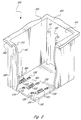
- FIG. 2 is an enlarged, fragmentary, isometric view of the socket of Figure 1.
- Figure 3 is a right side elevational view of the module of Figure 1.
- Figure 4 is a front elevational view of the module of Figure 1.
- Figure 5 is a bottom plan view of the module of Figure 1.
- Figure 6 is a top plan view of the module of Figure 1.
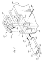
- Figure 7 is an enlarged, exploded isometric view of a latching assembly of the module of Figure 1.
- a portable medical electronic device 100 such as a defibrillator or medical monitor, is shown in Figure 1 as having a housing 102 enclosing medical electronic circuitry (not shown).
- a receiving socket 106 formed in a top side 104 of the housing 102 is sized to receive one or more feature modules 108.
- the module 108 includes a case 110 enclosing expanded functional circuitry (not shown), such as blood pressure monitoring or data recordation circuitry.
- the expanded functional circuitry electrically couples with the medical electronic circuit enclosed within the housing 102. In such manner, the functionality of the portable medical electronic device 100 may be altered or expanded by inserting one or more modules 108 into the socket 106.
- the socket 106 is defined by a front sidewall 112, a rear sidewall 114, a bottom wall 116, and left and right sidewalls, forming an approximately rectangular-shaped opening in the top side 104 of the housing 102.
- Three front ribs 120 project rearward from the front sidewall 112, each rib 120 extending from the bottom wall 116 toward the top side of the housing 104.
- the three front ribs 120 projecting from the front sidewall 112 are approximately equidistant from each other.
- the rear sidewall 114 has three equidistant rear ribs 121 projecting forward therefrom and extending from the bottom wall 116 toward the top side 104.
- case 110 of the module 108 has a bottom side 126, a front side 130, a rear side 132, a top side 142 and left and right sides.
- the socket 106 may receive one or more modules having at least three different widths.
- the module 108 depicted and generally described herein is a single width module.
- the socket 106 depicted and described herein is capable of accepting a module at least three times wider than the single width module 108.
- a module having twice the width of the module 108 may also be inserted into the socket 106.
- the case 110 is able to accommodate at least two printed circuit boards therein containing the expanded functional circuitry for that particular module. Modules having greater widths can accommodate greater numbers of printed circuit boards and therefore contain a greater amount of expanded functional circuitry. While the single width module 108 is discussed herein, the discussion applies generally to all other widths of modules.
- the front and rear sides 130 and 132 of the case 110 each have a channel 140 formed therein extending from the bottom side 126 of the case to the top side 142 of the case.
- the front and rear channels 140 are sized to receive one pair of front or rear ribs 120 and 121, respectively.
- Each channel 140 preferably extends approximately 2.9 inches from the bottom side 126 toward the top side 142 of the case 110.
- the front and rear sides 130 and 132, respectively, of the case 110 are preferably separated from each other by a distance of approximately 4.4 inches.
- Each channel 140 may extend inward with respect to the case 110 by a distance of approximately 0.27 inch. With these dimensions, each front rib 120 is separated from its corresponding rear rib 121 by approximately 4 inches.
- a housing electrical connector 122 projects upward from the bottom wall 116 of the socket 106 proximate to each front rib 120.
- a case electrical connector 124 protrudes from a bottom side 126 of the case 110 of the module 108.
- the housing electrical connector 122 and the case electrical connector 124 are selected from known connectors to securely electrically interconnect the module 108 and the electronic device 100 and are each preferably 15-pin connectors.
- Front and rear guide pins 128 and 129 project downward from the bottom side 126 of the module 108 on opposing sides of the case electrical connector 124.
- the front guide pin 128 projects from the bottom side 126 of the case 110 between the front side 130 of the case 110 and the case electrical connector 124.
- the rear guide pin 129 projects from the bottom side 126 of the case 110 between the rear side 132 and the case electrical connector 124.
- the center of the front guide pin 128 is preferably 0.7 inch from the center of the case electrical connector 124 and 0.5 inch from the front side 130 of the case 110.
- the centers of the front and rear guide pins 128 and 129 are preferably 1.5 inches apart in the front-to-rear direction. In the left-to-right direction, the front and rear guide pins 128 and 129 are preferably 0.5 inch apart.
- all measurements are with respect to a centerline down the appropriate side or surface.
- the front and rear guide pins 128 and 129 project below the bottom side 126 of the case 110 by approximately 0.28 inch, projecting a substantial distance beyond that of the case electrical connector 124 (which projects downward approximately 0.1 inch). By projecting proximate to and beyond the distance of the case electrical connector 124, the front and rear guide pins 128 and 129 protect the case electrical connector 124 from damaging impact should the module 108 be dropped onto its bottom side 126.
- a round hole 136 is formed in the bottom wall 116 of the socket 106, between each front rib 120 and each housing electrical connector 122, and is positioned and sized to receive the front guide pin 128 when the module 108 is inserted into the socket 106.
- an oblong hole 138 is formed in the bottom wall 116 between each housing electrical connector 122 and each rear rib 121, and is positioned and sized to receive the rear guide pin 129.
- the round and oblong holes 136 and 138 are thus separated from each other by approximately 1.5 inches.
- Each oblong hole 138 has a slight oblong shape extending in a front-to-rear direction between each pair of front and rear ribs 120 and 121, respectively, for reasons that will be explained below.
- the front and rear guide pins 128 and 129 preferably have chamfered ends 139, and the round and oblong holes 136 and 138 have mating tapering bottoms to receive the chamfered ends 139.
- the chamfered ends 139 of the front and rear guide pins 128 and 129 help guide the pins into their respective holes 136 and 138 when the module 108 is inserted into the socket 106.
- the guide pins 128 and 129 and the holes 136 and 138 are positioned off center so that the module 108 may be received by the socket 106 in only one orientation, thus preventing a user from fully inserting the module in the opposite orientation in which the housing electrical connector 122 and the case electrical connector 124 do not interconnect.
- a latching assembly for retaining the module 108 in the socket 106 is shown. While one such latching assembly is shown and described herein, the present invention may use a variety of latching assemblies to releasably retain the module 108 in the socket 106.
- a bolt slot 146 formed in the front side 130 of the case 110 proximate to the top side 142 slidably receives latch bolt 148.
- a pair of springs 150 are retained on a pair of spring pins 152 formed on and projecting rearward of the latch bolt 148. The springs 150 rest against a rear wall of the bolt slot 146 and bias the latch bolt 148 forward.
- a lever 154 retained on the top side 142 of the case 110 includes a gripping portion 156 and a pair of left and right camming arms 158.
- the camming arms 158 extend downward and between a forward extending head 166 formed in the latch bolt 148.
- the head 166 has a flat top surface 170 and a curved bottom surface 171.
- the left and right camming arms 168 rest against left and right shoulders 168 extending from left and right sides of the head 166 of the latch bolt 148.
- the springs 150 bias the latch bolt 148 forward, biasing the left and right shoulders 168 against the left and right camming arms 158.
- the left and right camming arms 158 are shaped so as to exert a pivot force on the lever 154 about the pin 164 when the left and right shoulders 168 exert a forward force against the camming arms.
- This pivot force causes the gripping portion 156 to pivot downward and rest against the top side 142 of the case 110 in a rest position.
- the head 166 projects forward between the left and right camming arms 156 and extends forward of the front side 130 of the case 110.
- the flat top surface 170 of the head 166 is adjacent to and below a ledge 172 ( Figure 2) formed in the housing 102 along an upper portion of the front sidewall 112 transverse to the front ribs 120.
- the ledge 172 projects rearward into the socket 106 and is positioned to releasably receive the flat top surface 170 of the head 166 when the module 108 is positioned in the socket.
- upward movement of the module 108 is restricted by the flat top surface 170 of the head 166 contacting the underside of the ledge 172.
- Downward movement of the module 108 is restricted by the bottom wall 116 of the socket 106.
- a user may remove the module 108 from the socket 106 by seizing the gripping portion 156 and pivoting it upward.
- the gripping portion 156 pivots upward about the pin 164, the left and right camming arms 158 pivot rearward and against the left and right shoulders 168 of the latch bolt 148.
- the latch bolt 148 slides rearward in the bolt slot 146, compressing the springs 150.
- the head 166 retracts to an unlatched position, away from contact with the ledge 172.
- the gripping portion 156 of the lever 154 is preferably ring-shaped or has a sufficient frictional gripping surface to allow a user to pull the module 108 from the socket 106 once the head 166 is retracted from engagement with the ledge 172.
- the lever 154 and the case connector 124 are positioned proximate to the front side of the case 130 so that when the module 108 is pulled from the socket 106 by means of the lever 154, a substantially upward force is exerted on the case electrical connector 124 as this connector pulls away from interconnection with the housing electrical connector 122.
- This substantially upward force minimizes any damaging torquing forces which may be placed on the case or housing electrical connectors 122 and 124 when the module 108 is removed from the socket 106.
- a substantially upward force is exerted on the front and rear guide pins 128 and 129 as they are pulled upward and out of the round and oblong holes 136 and 138. This upward force exerts minimal torquing force on the pins 128 which otherwise could frictionally bind the pins 128 in the holes 136, 138, thereby inhibiting removal of the module 108 from the socket 106.
- the user To reinsert the module 108, the user aligns the channels 140 in the front and rear sides 130 and 132 of the case 110 with the front and rear ribs 120 and 121; respectively, in the socket 106 and slides the module 108 downward.
- the ribs and channels provide an initial course adjustment to guide the module 108 into the socket 106 and align the front and rear guide pins 128 and 129 with the round and oblong holes 136 and 138, respectively.
- the pins 128, 129 Once the pins 128, 129 have been inserted into the holes 136, 138, respectively, the pins 128, 129 provide fine positioning to guide the case electrical connector 124 into the housing electrical connector 122.
- the rear guide pin 129 when received by the oblong hole 138, aligns the module 108 along a second axis perpendicular to the first axis, and prevents rotation of the module.
- the first and second axes are approximately parallel with the bottom wall 116.
- the case electrical connector 124 is in linear alignment with the grooves 140 with respect to the bottom side 126 of the case 110, and are preferably aligned along the centerline of the bottom side 126.
- the front and rear guide pins 128 and 129 are offset with respect to this line.
- the front and rear guide pins 128 and 129 are linearly aligned with the case electrical connector 124 and diagonally offset from the centerline, with the case electrical connector 124 being at the point of intersection between the centerline and the line intersecting the pins and the connector.
- the pins 128, 129 diagonally offset from the centerline of the module 108 the module is prohibited from rocking about a third axis perpendicular to the first and second axes.
- the longer sides of the oblong hole 138 (i.e., the left and right sides) contact opposing sides of the rear pin 129.
- the oblong hole has an oblong shape, and the front and rear pins 128 and 129 are placed close together relative to the size of the module 108, to permit a small degree of variability when inserting the module. This variability allows the module 108 to be adjusted or moved a small degree in order to align and couple the case electrical connector 124 with the housing electrical connector 122. This variability also compensates for variances in manufacturing.
- the curved bottom surface 171 of the head 166 is shaped such that when the head 166 contacts an upper edge of the ledge 172 upon insertion of the module 108, a downward force applied to the module 108 causes the latch bolt 166 to slide rearward and away from the ledge 172 as the curved bottom surface slides against the upper edge.
- a user need not lift the gripping portion 156 of the lever 154 to retract the latch bolt 148 when inserting the module 108 into the socket 106.
- An elastic seal 178 extends about the front side 130, the rear side 132, and the left and right sides of the case 110 proximate to the top side 142 and below the latch bolt 148.
- the elastic seals 178 about the modules contact the front sidewall 112, the rear sidewall 113, the left and right sidewalls, and each other to thereby form an environmental seal whereby particles or contaminants are inhibited from penetrating into the socket 106. Additionally, the elastic seals 178 provide shock-absorbing benefits to allow the modules 108 to withstand impact shocks imposed on them directly or through the device 100.
- a spacer (not shown) of the appropriate width having a similar elastic seal 178 about its exterior may be inserted into the empty slot or slots to ensure environmental integrity and absorb impact shock.
- Elastomeric gaskets 184 are secured between each housing electrical connector 122 and the bottom wall 116 of the housing 102.
- the case 110 is similarly sealed to inhibit the penetration of fluids into the interior of the module 108.
- the bolt slot 146 is sealed from the interior of the case 110.
- An elastomeric gasket (not shown), similar to the elastomeric gasket 184, is retained about the case electrical connector 124 and the bottom side 126.
- the top side 142 of the case 110 is designed to accommodate various connectors or ports allowing wires, cables, tubing or other transmission conduits 190 to be coupled between the module 108 and the exterior of the device 100.
- the device 100 includes a port 186 adjacent to the right sidewall of the socket 106, as shown in Figure 1.
- the port 186 is of sufficient size to accommodate the various diameters of various transmission conduits 190 extending from the upper surface of the modules 108 as shown in Figure 6.
- An area of the top side 142 of the case 110 is provided to accommodate a large variety of connectors, such as an external connector 188 shown in dashed lines in Figure 6.
- the module 108 can be a heart rate monitor wherein an electrical external connector 188 is provided in the area of the top side 142 to which wires 190 for electrodes may be coupled. Such wires can then be positioned through the port 186 to the exterior of the device 100.
- the module 108 can be a blood pressure monitor whereby the area of the top side 142 accommodates a pneumatic tube external connector 188.
- a pneumatic tube 190 coupled from the connector 188 can extend therefrom to the exterior of the device 100, through the port 186, to a blood pressure monitoring cuff.
- the present invention describes the portable medical electronic device 100 which allows the functions of the device to be readily changed or upgraded through the use of the modules 108.
- the modules 108 avoid impact shock and other environmental hazards inherent in a portable electronic device 100, yet allow ready insertion or removal of the module by using a two-step method of interconnecting the module to the electronic device.
- the first step when the module 108 is inserted into the socket 106, the front and rear channels 140 and front and rear ribs 120 and 121 align the front and rear guide pins 128 and 129 with the round and oblong holes 136 and 138, respectively.
- the front and rear guide pins 128 and 129 guide the case electrical connector 124 into the housing electrical connector 122 when the pins are received by the holes 136 and 138, respectively.
- the case and housing electrical connectors 124 and 122 are designed to further align themselves to electrically intercouple (e.g., having chamfered mechanical features and electrical sockets).
- the latching assembly allows the latch bolt 148 to extend into the bolt slot 146 and thereafter project outwardly therefrom to engage the ledge 172, releasably retaining the module 108 in the socket 106.
- No known system provides such a multi-step method of interconnecting a module with an electronic device. Interconnecting a module with an electronic device using ribs and channels alone, or pins and holes alone, is insufficient to provide both electrical interconnection capable of withstanding impact shock and ready insertion/removal of the module from the device.
- the front and rear pins 128 and 129 of the module 108 provide multiple benefits.
- the front and rear guide pins 128 and 129 align the module 108 along first and second perpendicular axes to prevent the module from shifting and rotating.
- the pins 128, 129 are also diagonally offset from the centerline of the module 108 to prohibit the module from rocking about the third perpendicular axis.
- the front and rear guide pins 128 and 129 protect the case electrical connector 124 by extending downward at a distance greater than that of the case electrical connector and by being positioned on opposing sides of the case electrical connector.
- the chamfered end 139 of each pin allows the pin to be readily and securely positioned within its respective hole.
Landscapes
- Health & Medical Sciences (AREA)
- Cardiology (AREA)
- Heart & Thoracic Surgery (AREA)
- Engineering & Computer Science (AREA)
- Biomedical Technology (AREA)
- Nuclear Medicine, Radiotherapy & Molecular Imaging (AREA)
- Radiology & Medical Imaging (AREA)
- Life Sciences & Earth Sciences (AREA)
- Animal Behavior & Ethology (AREA)
- General Health & Medical Sciences (AREA)
- Public Health (AREA)
- Veterinary Medicine (AREA)
- Details Of Connecting Devices For Male And Female Coupling (AREA)
Applications Claiming Priority (2)
| Application Number | Priority Date | Filing Date | Title |
|---|---|---|---|
| US207869 | 1994-03-08 | ||
| US08/207,869 US5529063A (en) | 1994-03-08 | 1994-03-08 | Modular system for controlling the function of a medical electronic device |
Publications (1)
| Publication Number | Publication Date |
|---|---|
| EP0671184A1 true EP0671184A1 (de) | 1995-09-13 |
Family
ID=22772316
Family Applications (1)
| Application Number | Title | Priority Date | Filing Date |
|---|---|---|---|
| EP95103279A Withdrawn EP0671184A1 (de) | 1994-03-08 | 1995-03-07 | Modular System zur Steuerung der Funktion einer elektronischen medizinischen Vorrichtung |
Country Status (3)
| Country | Link |
|---|---|
| US (1) | US5529063A (de) |
| EP (1) | EP0671184A1 (de) |
| CA (1) | CA2144113A1 (de) |
Cited By (1)
| Publication number | Priority date | Publication date | Assignee | Title |
|---|---|---|---|---|
| DE10134885A1 (de) * | 2001-07-18 | 2003-02-06 | Roche Diagnostics Gmbh | Modulares Analysesystem |
Families Citing this family (28)
| Publication number | Priority date | Publication date | Assignee | Title |
|---|---|---|---|---|
| US5605150A (en) * | 1994-11-04 | 1997-02-25 | Physio-Control Corporation | Electrical interface for a portable electronic physiological instrument having separable components |
| US5891051A (en) * | 1995-06-02 | 1999-04-06 | C.R. Bard, Inc. | Electronic urine monitor |
| USRE38533E1 (en) * | 1998-09-11 | 2004-06-15 | Life Corporation | Portable emergency oxygen and automatic external defibrillator (AED) therapy system |
| US6327497B1 (en) | 1998-09-11 | 2001-12-04 | Life Corporation | Portable emergency oxygen and automatic external defibrillator (AED) therapy system |
| US6598084B1 (en) | 1999-02-16 | 2003-07-22 | Sony Corporation | Methods and apparatus for processing, transmitting, and receiving data from a modular electronic medical device |
| US7645258B2 (en) | 1999-12-01 | 2010-01-12 | B. Braun Medical, Inc. | Patient medication IV delivery pump with wireless communication to a hospital information management system |
| US6985870B2 (en) | 2002-01-11 | 2006-01-10 | Baxter International Inc. | Medication delivery system |
| US8775196B2 (en) | 2002-01-29 | 2014-07-08 | Baxter International Inc. | System and method for notification and escalation of medical data |
| US10173008B2 (en) | 2002-01-29 | 2019-01-08 | Baxter International Inc. | System and method for communicating with a dialysis machine through a network |
| US8234128B2 (en) | 2002-04-30 | 2012-07-31 | Baxter International, Inc. | System and method for verifying medical device operational parameters |
| US20060194726A1 (en) * | 2004-05-25 | 2006-08-31 | Rueger David C | Methods of treating cartilage defects |
| EP1850734A4 (de) * | 2005-01-13 | 2009-08-26 | Welch Allyn Inc | Lebenszeichenmonitor |
| US10089443B2 (en) | 2012-05-15 | 2018-10-02 | Baxter International Inc. | Home medical device systems and methods for therapy prescription and tracking, servicing and inventory |
| US8057679B2 (en) | 2008-07-09 | 2011-11-15 | Baxter International Inc. | Dialysis system having trending and alert generation |
| US8554579B2 (en) | 2008-10-13 | 2013-10-08 | Fht, Inc. | Management, reporting and benchmarking of medication preparation |
| JP2015530659A (ja) | 2012-08-31 | 2015-10-15 | バクスター・コーポレーション・イングルウッドBaxter Corporation Englewood | 薬品依頼の履行システムおよび方法 |
| EP2911641B1 (de) | 2012-10-26 | 2018-10-17 | Baxter Corporation Englewood | Verbesserte arbeitsstation für medizinische dosiszubereitung |
| EP3779876B1 (de) | 2012-10-26 | 2025-06-18 | Baxter Corporation Englewood | Verbesserte bilderfassung für system zur zubereitung einer medizinischen dosis |
| EP4354450A3 (de) | 2014-06-30 | 2024-06-19 | Baxter Corporation Englewood | Verwalteter austausch medizinischer informationen |
| US11107574B2 (en) | 2014-09-30 | 2021-08-31 | Baxter Corporation Englewood | Management of medication preparation with formulary management |
| US11575673B2 (en) | 2014-09-30 | 2023-02-07 | Baxter Corporation Englewood | Central user management in a distributed healthcare information management system |
| WO2016065352A1 (en) | 2014-10-24 | 2016-04-28 | Baxter Corporation Englewood | Automated exchange of healthcare information for fulfillment of medication doses |
| SG11201704359VA (en) | 2014-12-05 | 2017-06-29 | Baxter Corp Englewood | Dose preparation data analytics |
| SG11201707114XA (en) | 2015-03-03 | 2017-09-28 | Baxter Corp Englewood | Pharmacy workflow management with integrated alerts |
| US11495334B2 (en) | 2015-06-25 | 2022-11-08 | Gambro Lundia Ab | Medical device system and method having a distributed database |
| DE102015117581A1 (de) * | 2015-10-15 | 2017-04-20 | Eugen Kagan | Modulares Intensivtherapiegerät |
| US11516183B2 (en) | 2016-12-21 | 2022-11-29 | Gambro Lundia Ab | Medical device system including information technology infrastructure having secure cluster domain supporting external domain |
| US10737105B2 (en) | 2017-10-02 | 2020-08-11 | Avive Solutions, Inc. | Modular defibrillator architecture |
Citations (2)
| Publication number | Priority date | Publication date | Assignee | Title |
|---|---|---|---|---|
| US3865101A (en) * | 1974-05-01 | 1975-02-11 | Datascope Corp | Portable and separable heart monitor and heart defibrillator apparatus |
| US4082084A (en) * | 1975-01-31 | 1978-04-04 | Medicor Muvek | Portable diagnostic device |
Family Cites Families (5)
| Publication number | Priority date | Publication date | Assignee | Title |
|---|---|---|---|---|
| US2970243A (en) * | 1957-07-30 | 1961-01-31 | Westinghouse Electric Corp | Electrical instrument mounting |
| US4981144A (en) * | 1985-03-18 | 1991-01-01 | Henry A. Carels, Jr. | Urine separation and collection device |
| US4919619A (en) * | 1989-03-29 | 1990-04-24 | A 'n D Cable Products, Inc. | Local area network transceiver cable lock |
| US5360005A (en) * | 1992-01-10 | 1994-11-01 | Wilk Peter J | Medical diagnosis device for sensing cardiac activity and blood flow |
| US5323291A (en) * | 1992-10-15 | 1994-06-21 | Apple Computer, Inc. | Portable computer and docking station having an electromechanical docking/undocking mechanism and a plurality of cooperatively interacting failsafe mechanisms |
-
1994
- 1994-03-08 US US08/207,869 patent/US5529063A/en not_active Expired - Fee Related
-
1995
- 1995-03-07 CA CA002144113A patent/CA2144113A1/en not_active Abandoned
- 1995-03-07 EP EP95103279A patent/EP0671184A1/de not_active Withdrawn
Patent Citations (2)
| Publication number | Priority date | Publication date | Assignee | Title |
|---|---|---|---|---|
| US3865101A (en) * | 1974-05-01 | 1975-02-11 | Datascope Corp | Portable and separable heart monitor and heart defibrillator apparatus |
| US4082084A (en) * | 1975-01-31 | 1978-04-04 | Medicor Muvek | Portable diagnostic device |
Cited By (3)
| Publication number | Priority date | Publication date | Assignee | Title |
|---|---|---|---|---|
| DE10134885A1 (de) * | 2001-07-18 | 2003-02-06 | Roche Diagnostics Gmbh | Modulares Analysesystem |
| DE10134885B4 (de) * | 2001-07-18 | 2004-02-05 | Roche Diagnostics Gmbh | Modulares Analysesystem |
| US6780064B2 (en) | 2001-07-18 | 2004-08-24 | Roche Diagnostics Operations, Inc. | Modular analytical system having at least two modules connected by a connecting plug |
Also Published As
| Publication number | Publication date |
|---|---|
| US5529063A (en) | 1996-06-25 |
| CA2144113A1 (en) | 1995-09-09 |
Similar Documents
| Publication | Publication Date | Title |
|---|---|---|
| US5529063A (en) | Modular system for controlling the function of a medical electronic device | |
| US11631949B2 (en) | Magnetic connector assembly | |
| US6146210A (en) | Connector assembly that prevents polarization problems and uses a single aperture to perform both latching functions and guide functions | |
| US6371787B1 (en) | Pull-to-release type latch mechanism for removable small form factor electronic modules | |
| CN100508298C (zh) | 收发器模块组件的释放机构 | |
| US7553188B2 (en) | Slide lock panel-mount connector | |
| EP0654186B1 (de) | Elektrischer verbindersockel mit auswurfvorrichtung für eine einsteckkarte | |
| US20060035506A1 (en) | Latching medical patient parameter safety connector and method | |
| US20090215283A1 (en) | Connector | |
| JP2002530822A (ja) | ガイド部材および取外しリセスを有する噛み合い電気コネクタアセンブリ | |
| EP0622868A2 (de) | Anschlussdosen-Montagesatz für Datenübertragung | |
| US6293813B1 (en) | Electrical connector with latching backplate assembly | |
| US5888101A (en) | Electrical connectors | |
| EP3596785B1 (de) | Blindsteckergehäuse und elektroniksystem | |
| US4952175A (en) | Key retention system | |
| CN101971434B (zh) | 连接器护盖 | |
| US6074232A (en) | Board to board electrical connector with releaseable actuator | |
| EP0646993A2 (de) | Elektrische Verbinderanordnung mit Nockenhebel Verriegelungsmechanismus | |
| US6913474B2 (en) | Connector coupling mechanism, system and method | |
| US4832624A (en) | Key retention system | |
| EP4002601B1 (de) | An eine anschlussöffnung angepasste schutzabdeckung und anschlussöffnungsvorrichtung damit | |
| US5957728A (en) | Data transmission adapter | |
| US12294168B2 (en) | Electrical receptacle connector and electrical connector assembly having the same | |
| US4125278A (en) | Plug-in connector | |
| US6000965A (en) | Retaining apparatus for a connector |
Legal Events
| Date | Code | Title | Description |
|---|---|---|---|
| PUAI | Public reference made under article 153(3) epc to a published international application that has entered the european phase |
Free format text: ORIGINAL CODE: 0009012 |
|
| AK | Designated contracting states |
Kind code of ref document: A1 Designated state(s): CH DE FR GB IT LI |
|
| 17P | Request for examination filed |
Effective date: 19960307 |
|
| RAP1 | Party data changed (applicant data changed or rights of an application transferred) |
Owner name: PHYSIO-CONTROL CORPORATION |
|
| STAA | Information on the status of an ep patent application or granted ep patent |
Free format text: STATUS: THE APPLICATION IS DEEMED TO BE WITHDRAWN |
|
| 18D | Application deemed to be withdrawn |
Effective date: 19991001 |