EP0671291A2 - Fahrzeugsitz für Kinder - Google Patents
Fahrzeugsitz für Kinder Download PDFInfo
- Publication number
- EP0671291A2 EP0671291A2 EP95301189A EP95301189A EP0671291A2 EP 0671291 A2 EP0671291 A2 EP 0671291A2 EP 95301189 A EP95301189 A EP 95301189A EP 95301189 A EP95301189 A EP 95301189A EP 0671291 A2 EP0671291 A2 EP 0671291A2
- Authority
- EP
- European Patent Office
- Prior art keywords
- seat
- child
- cushion
- assembly
- adult
- Prior art date
- Legal status (The legal status is an assumption and is not a legal conclusion. Google has not performed a legal analysis and makes no representation as to the accuracy of the status listed.)
- Granted
Links
Images


Classifications
-
- B—PERFORMING OPERATIONS; TRANSPORTING
- B60—VEHICLES IN GENERAL
- B60N—SEATS SPECIALLY ADAPTED FOR VEHICLES; VEHICLE PASSENGER ACCOMMODATION NOT OTHERWISE PROVIDED FOR
- B60N2/00—Seats specially adapted for vehicles; Arrangement or mounting of seats in vehicles
- B60N2/24—Seats specially adapted for vehicles; Arrangement or mounting of seats in vehicles for particular purposes or particular vehicles
- B60N2/26—Seats specially adapted for vehicles; Arrangement or mounting of seats in vehicles for particular purposes or particular vehicles for children
-
- B—PERFORMING OPERATIONS; TRANSPORTING
- B60—VEHICLES IN GENERAL
- B60N—SEATS SPECIALLY ADAPTED FOR VEHICLES; VEHICLE PASSENGER ACCOMMODATION NOT OTHERWISE PROVIDED FOR
- B60N2/00—Seats specially adapted for vehicles; Arrangement or mounting of seats in vehicles
- B60N2/24—Seats specially adapted for vehicles; Arrangement or mounting of seats in vehicles for particular purposes or particular vehicles
- B60N2/30—Non-dismountable or dismountable seats storable in a non-use position, e.g. foldable spare seats
- B60N2/3081—Seats convertible into parts of the seat cushion or the back-rest or disapppearing therein, e.g. for children
- B60N2/3084—Disappearing in a recess of the back-rest
Definitions
- This invention relates to vehicle seats and more particularly to integrated seats for motor vehicles capable of being moved between an adult mode position and a child mode position.
- Integrated seats which contemplate both a child and an adult mode are to be contrasted with the general practice which exists wherein the seats provided are adult seats and separate child seat units are used to accommodate children.
- the usual situation is that the separate units contain their own seat belt assemblies or occupant restraints and the separate child's unit is affixed to the existing adult seat by strapping the separate child unit to the adult seat by the adult seat belt assembly.
- a characteristic of the separate child unit commercially available is that they are used for limited periods of time during the growth years. For example, it is usual to provide a separate infant unit which is used only during the first year or until the child reaches a weight of about twenty pounds. Thereafter, a different separate child's unit must be used. During the period from one year up to six or seven, the child's weight and dimensions increase significantly and the child's ability changes from one in which an adult must interface the child with the seat and restraint system to one in which the child becomes capable of interfacing with the seat and restraint system.
- the patented literature contains many proposals for eliminating this inconvenience inherent in the use of separate child seat units by providing an integrated seat structure capable of being easily and conveniently moved between an adult mode position and a child mode position.
- Examples of such patented literature include U. S. Patent Nos. 4,540,216, 4,756,573, 4,900,087, 4,943,112, 4,986,600, 5,282,667, and 5,282,668, British Patent No. 2,023,415, and German Offenlegungsscrift 27 20 954.
- the present invention is based upon the underlying thought that, in order for an integrated seat to achieve widespread acceptance, it must advantageously be convenient to use, easy to deploy, and offer adequate protection for child seat occupant sitting in the seat when the seat is in the child mode position.
- the seat comprises a seat frame assembly for securement within the motor vehicle interior, and a seat cushion carried by the seat frame assembly in a position to enable an adult occupant of the motor vehicle to sit thereon.
- a seat back frame assembly is mounted in operative relation with respect to the seat frame assembly, and side cushions are carried by the seat back frame assembly in positions to be engaged by the back of an adult seat occupant sitting on the seat cushion.
- the side cushions are spaced apart a distance sufficient to define a space therebetween of a size to enable a child to be disposed therebetween.
- the plurality of cushion assemblies include (1) a movable first cushion assembly mounted for movement between (a) the adult mode position wherein the movable first cushion assembly is disposed within the space and provides a cushioned adult seat back lower portion for engaging the lower back of an adult seat occupant sitting on the seat cushion, and (b) the child mode position wherein the movable first cushion assembly is disposed in such a position so as to provide a child's seat support in overlying relation to the seat cushion, and (2) a movable second cushion assembly including an upper cushioned pad disposed in the space and providing support to an adult seat occupant sitting on the seat cushion when the cushion assemblies are in the adult mode position.
- the movable second cushion assembly is operatively connected to the first cushion assembly so that movement of the movable first cushion assembly causes responsive movement of at least the upper cushioned pad of the movable second cushion assembly.
- the upper cushioned pad is moved i) upwardly in response to movement of the first cushion assembly from the adult mode position to the child mode position so that the upper cushioned pad provides support to the back of the head of a child seat occupant sitting on the movable first cushion assembly providing the child's seat support in overlying relation to the seat cushion, and ii) downwardly in response to movement of the first cushion assembly from the child mode position to the adult mode position so that the upper cushioned pad provides support to an adult seat occupant sitting on the seat cushion when the cushion assemblies are in the adult mode position.
- a harness assembly constructed and arranged for extension over the shoulders of a child seat occupant sitting on the child seat when said plurality of cushion assemblies are in the child mode position, the harness assembly having an anchor point disposed between the legs of a child seat occupant.
- an integrated child seat has at least the child seat back rigidly or pivotally fixed to the automobile seat back frame.
- the child seat support rests upon the adult seat cushion when deployed.
- the child seat back is reclined, for example, when an adult is occupying a portion of the seat adjacent to the deployed child seat, the child seat back will be moved therewith and reclined as well.
- the child seat back is reclined in this fashion, the child seat typically remains resting on the adult seat as the child seat and child seat back are not fixed in angular relation to one another.
- integrated child seats of this type are normally provided with at least a three point child seat harness, with one of said points being provided by a crotch belt disposed between the legs of the child seat occupant, such sudden stoppages may impose an uncomfortable load on the child's crotch area via the crotch belt, as opposed to the preferred situation wherein the majority of the load is absorbed by the child's upper torso through shoulder belts forming the other two points of the three point harness.
- the child seat back is inclined at a greater angle with respect to vertical than the back of an adult seat back.
- the adult seat back is preferably inclined at an angle of about 40° to vertical when the child is sleeping and about 30° to vertical when the child is awake.
- Patents 4,986,600, 5,026,118 and 5,100,199 provide for adjustment of the inclination of the child seat back in coordination with the forward movement of the child seat in supported relation on the adult seat. Here again the angular relation between the child's back and seat is increased beyond optimum.
- the seat comprises a seat frame assembly for securement within the motor vehicle interior.
- a seat cushion is carried by the seat frame assembly in a position to enable an adult occupant of the motor vehicle to sit thereon.
- a seat back frame assembly is mounted in operative relation with respect to the seat frame assembly, and side cushions are carried by the seat back frame assembly in positions to be engaged by the back of an adult seat occupant sitting on the seat cushion.
- the side cushions are spaced apart a distance sufficient to define a space therebetween of a size to enable a child to be disposed therebetween.
- a plurality of cushion assemblies constructed and arranged to be moved between i) an adult mode position wherein the cushion assemblies are disposed within the space and provide support to the back of an adult seat occupant sitting on the seat cushion with a desired angular relationship between the adult seat occupant's seat and back and ii) a child mode position wherein the cushion assemblies provide a cushioned child seat, a cushioned child seat back, and a cushioned child head support for supporting the seat, back and head of a child seat occupant respectively.
- the plurality of cushion assemblies include (1) a movable first cushion assembly mounted for movement between (a) the adult mode position wherein the movable first cushion assembly is disposed within the space and provides a cushioned adult seat back lower portion for engaging the lower back of an adult seat occupant sitting on the seat cushion, and (b) the child mode position wherein the movable first cushion assembly extends in self-sustaining cantilevered overlying relation to the seat cushion to provide a child's seat support which extends forwardly and upwardly to a greater extent than the seat support provided by the seat cushion, and (2) a movable second cushion assembly providing a child's seat back support disposed within the space inwardly of the first movable cushion assembly when the cushion assemblies are in the adult mode position.
- the movable second cushion assembly is operatively connected to the first cushion assembly so that movement of the movable first cushion assembly causes responsive movement of the movable second cushion assembly.
- the movable second cushion assembly is movable i) angularly in one direction in response to movement of the first cushion assembly from the adult mode position to the child mode position so that the child's seat back support extends upwardly and rearwardly to a greater extent than the adult back support and provides support to the back of a child seat occupant sitting on the child's seat support provided by the movable first cushion assembly with a desired angular relationship between the child seat occupant's seat and back, and ii) angularly in an opposite direction in response to movement of the first cushion assembly from the child mode position to the adult mode position.
- a harness assembly is constructed and arranged for extension over the shoulders of a child seat occupant sitting on the child seat when the plurality of cushion assemblies are in the child mode position, the harness assembly having an anchor point disposed between the legs of a child seat occupant.
- the arrangement described above has advantages irrespective of whether the adult seat back is fixed or capable of reclining, both of which are contemplated by the present invention.
- the child seat back can be inclined rearwardly to a position (e.g. 35 from vertical) which is between a desireable upright position (e.g. 30 from vertical) and a desirable sleeping position (e.g. 40 from vertical) while still maintaining a desireable angular relationship between the childs back and seat.
- a reclining seat back the desired angular relationship between the child's back and seat is maintained through any desired position of inclination that is set
- the invention can be used with either low back rests such the bench type vehicles, or high back rests as provided in sedan motor vehicles which have fixed or stationary head supports.
- FIG. 1 an automobile seat, generally indicated at 10, embodying the principles of the present invention, the seat 10 being shown mounted on the floor 12 of a motor vehicle 14.
- the seat 10 shown is a two occupant bench seat of the type installed in the middle of a van type motor vehicle having a side entrance door (not shown) near the side of the seat, as shown.
- the left operative position of the bench seat 10 is provided with a child's seat module, generally indicated at 18, embodying the principles of the present invention. It will be understood that an additional, similar child's seat module 18 may also be provided in the right-hand operative position of the bench seat 10.
- the child's seat module 18 of the present invention is suitable to be fixed to the seat back frame of any vehicle seat, including single, tandem, or three-occupant bench seats with fixed or movable seat backs.
- the two-occupant bench seat 10 shown is considered to be particularly desirable since it is a seat, which by virtue of the type of motor vehicle involved, will often be occupied by one or more children.
- the two-occupant bench seat 10 presents particular requirements because of the relatively low back construction provided in conventional bench seats of this type heretofore utilized, when compared, for example, to the seat back in the back of a sedan type motor vehicle. It will be understood that certain principles of the present invention are applicable only to the low back seat as shown, while other principles are directed to both high back and low back seats as mentioned hereinbefore.
- the two occupant bench seat 10 includes a pair of spaced risers 20 of conventional construction including lever actuated gripper assemblies (not shown) for releasably gripping floor cleats (not shown) so as to enable the seat 10 to be readily removed.
- a main seat frame 22 Fixed to the upper ends of the risers 20 is a main seat frame 22 likewise of conventional construction.
- the main seat frame 22 is shown somewhat schematically as being a tubular rectangular peripheral structure having suitable springs 24 suspended in the open central position on which is supported a covered seat cushion 26 of conventional construction. As shown, the width of the seat cushion 26 is sufficient to enable two adult seat occupants to sit thereon in side-by-side operative positions.
- the seat is provided with an adult seat belt assembly 16 for use by an adult sitting on seat cushion 26.
- the seat 10 also is provided with a seat back frame, generally indicated at 28, which also is preferably of conventional configuration.
- the seat back frame 28 includes a main inverted U-shaped frame member 30 positioned so that the lower free ends of the leg positions are rigidly fixed to the rearward sides of the main seat frame 22 and the central bight portion extends along the upper extent of the seat back.
- a lower tubular horizontal frame member 32 is welded or otherwise fixed between the leg positions of the main U-shaped frame member 30.
- the seat back is modified to accept the child's seat module 18.
- the adult seat belt assembly 16 is mounted within the motor vehicle 14 in a position to cooperate with a seat occupant sitting on the left-hand operational position of the seat cushion 26.
- the adult seat assembly 16 can assume different configurations, however, as shown, the assembly 16 includes a belt section 42 fixed to the rearward central position of the main seat frame 22 and extending therefrom forward between the seat cushion 26 and the seat back side cushion 36.
- the belt section 42 carries a releasable buckle assembly 44 of conventional construction at its opposite end.
- a main belt section 46 is anchored at one end to the floor, as indicated at 48, and extends therefrom over a fixed guide 50 mounted on the left side of the vehicle near the roof. From the fixed guide 50, the belt section 46 extends downwardly to a take up reel assembly 52 of conventional construction suitably mounted in the left side of the vehicle 14. The extent of the belt section 46 extending from the floor anchor 48 to the roof guide 50 has a clip element 54 slidable thereon capable of being releasably engaged by the buckle assembly 44.
- an adult occupant in the left operative position on the seat cushion 26 is able to move the seat belt assembly 16 into operative relation by grasping the clip element 54 and bringing it across that seat occupant's chest into engaged relation to the buckle assembly 44.
- a lower extent of the belt section 46 between the floor anchor 48 and the clip element 54 extends over the seat occupant's waist and an upper extent of the belt section 46 between the clip element 54 and the fixed guide 50 extends across the left shoulder of the seat occupant.
- the child's seat belt assembly 82 (see Fig. 1) of the module 18 is used as a restraint for the small child in the child's seat module 18.
- the child's seat belt assembly 82 is movable into a child's booster seat position so that the child seat module can be used with a larger child (e.g. above 40 pounds). To accomplish this, the child's seat belt assembly 82 is moved into the booster seat position by detaching the cushion pad 68, as shown in Figure 1, and replacing it so that the child's seat belt assembly 82 is disposed rearwardly and beneath the cushion pad 68. In this way, the child's seat belt assembly 82 remains with the module 18 for use simply by detaching the cushion pad 68, deploying the child's seat belt assembly 82 and then replacing the cushion pad 68.
- a larger child e.g. above 40 pounds
- the module 18 acts as a booster seat for the larger child enabling the larger child to more conveniently see out of the vehicle windows and to more conveniently effect restraint by simply using the adult seat belt assembly 16.
- the modification required is to replace the normal seat back cushion mounted forwardly of the seat back frame 28 with a pair of side cushions 34 and 36 spaced apart a distance sufficient to fit a child therebetween.
- the side cushion 34 and 36 fixed forwardly of the frame 28 are suitably covered.
- a conventional backing 38 is provided rearwardly of the frame 28.
- the spacing between the side cushions 34 and 36 defines a space 40 between the side cushions 34 and 36 forwardly of the seat back frame 28 sufficient to receive a child therebetween and within which to mount the child's seat module 18.
- the child seat module 18 includes a plurality of cushion assemblies 60 carried by and connected with the seat back frame 28.
- the cushion assemblies 60 include a lower movable seat cushion assembly (or “first cushion assembly”), generally indicated at 64, an upper movable cushion assembly (or “second cushion assembly”), generally indicated at 66, and a cushion pad, generally indicated at 68.
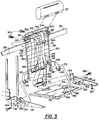
- the movable cushion assemblies 60 are movable between i) an adult mode position (e.g., see left hand side of seat in Figure 2) wherein the cushion assemblies 60 are disposed within the space 40 and provide support to the back of an adult seat occupant sitting on the seat cushion 26 and ii) a child mode position (e.g., see right hand side of seat in Figure 2) wherein the cushion assemblies provide a cushioned child seat, a cushioned child seat back, and a cushioned child seat head support for supporting the seat, back and head of a child seat occupant respectively.
- an adult mode position e.g., see left hand side of seat in Figure 2
- a child mode position e.g., see right hand side of seat in Figure 2
- the cushion assemblies provide a cushioned child seat, a cushioned child seat back, and a cushioned child seat head support for supporting the seat, back and head of a child seat occupant respectively.
- the lower movable seat cushion assembly 64 includes an foamed cushion 74 having an outer fabric cover 76, and a rigid structure 78 (see Figure 6).
- the cushion assembly 64 may also be provided with a nylon pull strap 84, which can be pulled outwardly to deploy the child seat.
- a more detailed description of the construction of cushion assembly 64 is disclosed in U.S. Patent No. 5,224,756.
- the lower moveable seat cushion assembly 64 is mounted for movement between (a) the adult mode position wherein the movable seat cushion assembly 64 is disposed within the space 40 and provides a cushioned adult seat back lower portion for engaging the lower back of an adult seat occupant sitting on the seat cushion 26, and (b) the child mode position wherein the lower movable seat cushion assembly 64 is disposed in such a position so as to provide a child's seat support in overlying relation to the seat cushion 26.
- the upper movable cushion assembly 66 includes an upper cushioned pad 67.
- the upper cushioned pad 67 When in the adult mode, the upper cushioned pad 67 is substantially disposed in space 40 and provides support to an adult seat occupant sitting on seat cushion 26.
- the upper movable cushion assembly 66 is operatively connected to the lower cushion assembly 64 through a child seat back frame 80 so that movement of the lower cushion assembly 64 causes responsive movement of the upper cushioned pad 67.
- the upper cushioned pad is moved i) upwardly in response to movement of the lower cushion assembly 64 from the adult mode position to the child mode position so that the upper cushioned pad 67 provides support to the back of the head of a child seat occupant sitting on the lower cushion assembly, and ii) downwardly in response to movement of the cushion assembly from the child mode position to the adult mode position so that the upper cushioned pad provides support to an adult seat occupant sitting on seat cushion 26 when said cushion assemblies are in the adult mode position.
- the lower seat cushion assembly 64 extends from the bottom of the space 40 in overlying relation to the seat cushion 26 so as to provide, with a seat portion 70 of the cushion pad 68 detachably mounted thereon, a cushioned child's seat.
- the foamed cushion 74 of lower seat cushion assembly 64 does not contact seat cushion 26, but is somewhat inclined relative thereto and rigidly maintained as such when the cushion assemblies 60 are in the child mode position.
- the cushion pad 68 is detachably mounted with respect to the lower seat cushion assembly 64 and the child seat back frame 80 to provide a cushioned child's seat.
- the detachable securement of the cushion pad 68 is provided so that the pad can be cleaned easily.
- Any suitable means may be used to accomplish this detachable mounting, such as Velcro strips. The provision of such Velcro strips to accomplish this function is disclosed in our previously filed U.S. Patent Application.
- a child's seat belt assembly is carried by the child seat back frame 80.
- the child's seat belt assembly 82 of the module 18 is used as a restraint for the child.
- the child's seat module 18 is shown therein in exploded perspective so as to show its construction and illustrate the manner in which it is mounted on the seat back frame 28 between the side cushions 34 and 36.
- the child seat back frame 80 includes fixed guide members 86 rigidly attached or affixed to the seat back frame 28 by suitable fasteners, as indicated at 90.
- the child seat back frame 80 includes a pair of spaced vertical rod members 92 which are integrally connected at their upper ends by a horizontal rod member 94 and have a plurality of evenly spaced horizontal wire members 95 extending therebetween. It can be appreciated that the rod members 92 and/or 94 can be provided with the aforementioned Velcro strips in order to secure the cushion pad 68 thereto. Alternatively, any other suitable means, such as cloth ties, for securing the pad to the frame 80. may be provided.
- the child seat back seat frame 80 is also provided with a horizontal head support bar 96 attached to vertical rod members 92 by attachments 98. Both ends of bar 96 extend past the attachments 98 and are bent upwardly to terminate in upwardly projecting stem portions 100.
- the stem portions 100 are disposed substantially in parallel to the vertical rod members 92.
- Fixed guide members 86 are provided with substantially annular bushings 104 which receive the aforementioned stem portions 100 in slidable relation.
- the lower portions of vertical rod members 92 are bent to form substantially annular portions 108 closed off by a suitable closure, as indicated by 110.
- the annular portions 108 are operatively connected to lower cushion assembly 64 via a four-bar linkage assembly generally indicated at 114.
- the lower seat cushion assembly 64 includes a rigid structure, generally indicated at 78 in the form of a rectangular seat pad support platform molded of suitable structural plastic material.
- a pair of parallel movable side support members or brackets 116 are disposed on opposite sides of the rigid structure 78.
- Movable brackets 116 and rigid structure 78 are provided with respective openings 120 and 122, which are adapted to having suitable fasteners 124 extended therethrough to secure the rigid structure 78 to the movable brackets 116.
- a pair of mounting anchor members or brackets 134 are rigidly fixed to the seat back frame 28, and each are respectively cooperable with one of the movable brackets 116 through a pair of bar links or link members 138 and 140.
- Movable brackets 116 are each provided with plural (two) openings 128 and 130. Openings 128 of the opposing brackets are axially aligned with one another, as are openings 130.
- Each of the bar links or link members 138 and 140 are each pivotally mounted via a suitable fastener (e.g., bolts 132) at one end to one of the mounting brackets 134, and at the other end to one of the movable brackets to provide a four bar linkage on each side of the rigid structure as shown in Figure 3. The four bar linkage will be described in greater detail later.
- a crotch belt section 140 which form part of the child seat belt assembly 82, extends upwardly through opening 144 in the rigid structure 78.
- a conventional seat restraint belt buckle assembly 148 is secured to the exposed forward end of the crotch belt section 140.
- the opposite end of the belt section 140 (not shown) is suitably fastened to an underside portion of rigid structure 78.
- the child seat belt assembly 82 also includes a take-up reel 150, which is mounted on a rearward portion of rigid structure 78 via suitable fasteners 151.
- the take-up reel generally serves as a belt tension adjuster and may be any conventionally known take-up reel, as, for example, the automatic locking retractor type (ALR) or emergency locking retractor type (ELR) or a combination of these two types.
- the different types of take-up reels utilize different criteria and structures (e.g., such as an inertia latch in the ELR) to shift from a pay-out to locking mode.
- Such take-up reels are commonly available, for example, from Indiana Mills and Manufacturing Inc.
- the ALR type reel is used.
- a single belt 152 Extending outwardly from the take-up reel is a single belt 152, which is secured at an opposite end thereof to a dividing bracket 156, which in turn has a pair of twin shoulder belts 112 and 115 extending therefrom.
- the shoulder belts 112 and 115 extend upwardly from the dividing bracket 156 and are looped over a belt mounting rod 160 secured to seat back frame 28, and then extend through openings 161 in upper cushion pad 67 (see Figs. 1, 4 and 6).
- the cushion pad 67 can be provided with a recess in the headrest.
- mounting rod 160 can be integrally formed with the aforementioned fixed guide members 86.
- the shoulder belts 112 and 115 pass through a releasably interconnected guide member 164 and slotted ends of a pair of opposite hand connector members 166.
- the latter are adapted to be releasably connected to the buckle assembly 148.
- Extensions 170 and 172 of the respective belts 115 and 112 are each secured at one end thereof by brackets 174 to respective ones of the movable brackets 116.
- the extensions 124 and 126 serve to mount over the child's thighs.
- the cushion pad 68 has the seat and back portions 70 and 72 connected by a flexible hinge 178 and a rectangular cut-out opening 180 is formed in the seat portion 70 for mounting around the crotch belt 140 out of the rigid structure 78.
- the upper edge of the back portion 72 fits against the child seat back frame 80 up to a point just below the upper cushioned pad 67.
- Figure 4 shows the child seat module substantially assembled in the child mode position, but with some portions missing (e.g., padding) to reveal others better.
- Figure 5 is similar to Figure 4, but shows the child seat module in the adult mode position.
- the child seat back frame 80 is disposed higher in relation to mounting brackets 134 when in the child mode position than when in the adult mode position.
- the child seat back frame 80 has the lower annular portions 108 of vertical rod members 92 pivotally connected to an appropriate location on movable brackets 116 by suitable fasteners 186.
- peripheral side surfaces of bar links 138 and 140 abut against one another to define the upper and lower positions of travel for the lower movable cushion assembly 64, including brackets 116 and rigid structure 78.
- abutment is designated by numeral 200
- Figure 5 such abutment is designated by numeral 202.
- the child seat module is shown in both the adult mode and child mode positions.
- the adult mode position is substantially shown with dashed lines.
- seat 204 which includes seat cushion 26 can be disposed at a desired angular relationship with respect to seat back 206.
- the lower movable cushion assembly 64 extends in self sustaining cantilevered overlying relation to seat cushion 26 to provide a child's seat support which extends forwardly and upwardly to a greater extent than the seat support provided by the seat cushion 26.
- the movable upper cushion assembly 66 provides a child's seat back support (e.g., frame 80), which disposed within space 40 inwardly of the lower movable cushion assembly 64 when the cushion assemblies are in the adult mode position.
- the movable upper cushion assembly 66 including frame 80, is operatively connected to the lower movable cushion assembly 64 so that movement of said lower movable cushion assembly 64 causes responsive movement of the movable upper cushion assembly 66.
- the movable upper cushion assembly 66 is movable angularly in a first direction in response to movement of the lower cushion assembly 64 from the adult mode position to the child mode position so that the child's seat back support (e.g., frame 80) extends upwardly and rearwardly to a greater extent than the adult back support as provided by, for example, side cushions 34, 36 or foamed cushion pad 74 when lower cushion assembly 64 is in the adult mode.
- frame 80 provides support to the back of a child seat occupant sitting on said child's seat support provided by the movable lower cushion assembly 64 with a desired angular relationship between the child seat occupant's seat and back.
- the movable upper cushion assembly 66 is also movable angularly in second direction, opposite to the first direction, in response to movement of the lower cushion assembly 64 from the child mode position to the adult mode position.
- seat back 206 is preferably disposed at an angle of about 29° relative to arrow A, which is normal to the vehicle floor 12. As can be appreciated, this angle can be varied to meet various safety requirements and specifications.
- seat 204 is disposed at an inclined angle of approximately 10° to the vehicle floor, and thus the angular relation between the seat 204 and back 206 is approximately 109°. Again, it is possible to alter this angular configuration as desired. While it is preferred that the angle formed between seat 204 and back 206 be generally fixed at 29° to vertical, the present invention contemplates that the seat back 206 may be reclined relative to the seat 204 with any conventional reclining mechanism. It is also possible to provide a seat and back which have a permanently fixed angle therebetween, but tiltable together as a unit to alter the angle of the back to normal.
- the angle between the child seat back and child seat in the child mode position will remain fixed regardless of reclining or tilting of the seat back 206 and/or seat 204.
- this fixed angle is between the range of 95° and 105°. This advantageously allows an adult seat occupant (e.g., sitting in the left hand side seat in Figure 1) to recline the adult seat back 206 relative to the adult seat 204 without causing a corresponding increase in the angle between the child seat back and child seat.
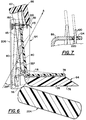
- the child seat back frame 80 provides a child's back support at an angle of about 35° to vertical (arrow A in Figure 6). This 35° angle strikes a compromise between the aforementioned desired 29° incline for an adult seat back and a desired 40° incline for a child sleeping in a child seat.
- the upper cushioned pad 67 has a lower beveled surface 210 having the openings 161 through which shoulder belts 112 and 115 extend. Although belts 112 and 115 extend through the cushioned pad, belt mounting rod 160, which is disposed at a position higher than the openings 161, operates as the true anchor point for said belts.
- This configuration eliminates the need for providing adjustable shoulder belt slots, as such accommodation is provided in the automatically translating upper cushioned pad 67. It should be noted that by constructing the lower portion of cushioned pad 67 substantially in a wedge shape as with beveled surface 210, the cushioned pad continues to provide a comfortable head support without requiring the child to strain his or her neck.
- an outer cloth or other "fabric" surface material, such as vinyl or leather, cover 76 is wrapped around foam cushion 74 of the cushion assembly 64.
- the manner in which foam cushion and the surrounding cover is secured to rigid structure 78 may be accomplished as disclosed in the aforesaid U.S. Patent No. 5,224,756.
- FIG. 7 is a sectional side view of a fixed guide member 86 of the present invention, including the respective annular bushing 104 thereof which receives the aforementioned respective stem portion 100 in slidable relation.
- annular bushing 104 is preferably made from an elastomeric material and is adapted to act as a slide permitting pivot point for stem portion 100.
- the bushing 104 has an inner rounded surface 220 and an appropriate inner diameter which causes stem portion 100 to be effectively wedged therein when the child seat module 18 is disposed in both the adult mode position and the child mode position. This wedge effect muffles noise created within the vehicle due to rattling and/or vibratory movement in the child seat back frame 80 which might occur during movement of the vehicle.
- a motor vehicle seat providing an integrated child seat comprising: a seat frame assembly for securement within the motor vehicle interior; a seat cushion carried by said seat frame assembly in a position to enable an adult occupant of the motor vehicle to sit thereon; a seat back frame assembly mounted in operative relation with respect to said seat frame assembly; side cushions carried by said seat back frame assembly in positions to be engaged by the back of an adult seat occupant sitting on said seat cushion, said side cushions being spaced apart a distance sufficient to define a space therebetween of a size to enable a child to be disposed therebetween; a plurality of cushion assemblies constructed and arranged to be moved between i) an adult mode position wherein said cushion assemblies are disposed within said space and provide support to the back of an adult seat occupant sitting on said seat cushion and ii) a child mode position wherein said cushion assemblies provide a cushioned child seat, a cushioned child seat back, and a cushioned child head support for supporting the seat, back and head of a
- a motor vehicle seat providing an integrated child seat comprising: a seat frame assembly for securement within the motor vehicle interior; a seat cushion carried by said seat frame assembly in a position to enable an adult occupant of the motor vehicle to sit thereon; a seat back frame assembly mounted in operative relation with respect to said seat frame assembly; side cushions carried by said seat back frame assembly in positions to be engaged by the back of an adult seat occupant sitting on said seat cushion, said side cushions being spaced apart a distance sufficient to define a space therebetween of a size to enable a child to be disposed therebetween; a plurality of cushion assemblies constructed and arranged to be moved between i) an adult mode position wherein said cushion assemblies are disposed within said space and provide support to the back of an adult seat occupant sitting on said seat cushion and ii) a child mode position wherein said cushion assemblies provide a cushioned child seat, a cushioned child seat back, and a cushioned child head support for supporting the seat, back and head of a child
- a motor vehicle seat providing an integrated child seat comprising: a seat frame assembly for securement within the motor vehicle interior; a seat cushion carried by said seat frame assembly in a position to enable an adult occupant of the motor vehicle to sit thereon; a seat back frame assembly mounted in operative relation with respect to said seat frame assembly; side cushions carried by said seat back frame assembly in positions to be engaged by the back of an adult seat occupant sitting on said seat cushion, said side cushions being spaced apart a distance sufficient to define a space therebetween of a size to enable a child to be disposed therebetween; a plurality of cushion assemblies constructed and arranged to be moved between i) an a adult mode position wherein said cushion assemblies are disposed within said space and provide support to the back of an adult seat occupant sitting on said seat cushion with a desired angular relationship between the adult seat occupant's seat and back and ii) a child mode position wherein said cushion assemblies provide a cushioned child seat, a cushioned
- said movable second cushion assembly includes an upper cushioned pad disposed in said space and providing support to an adult seat occupant sitting on said seat cushion when said cushion assemblies are in said adult mode position. It may be arranged that said upper cushioned pad is capable of being moved i) upwardly in response to movement of said first cushion assembly from said adult mode position to said child mode position so that said upper cushioned pad provides support to the back of the head of a child seat occupant sitting on said movable first cushion assembly providing said child's seat support in said overlying relation to said seat cushion, and ii) downwardly in response to movement of said first cushion assembly from said child mode position to said adult mode position so that said upper cushioned pad provides support to an adult seat occupant sitting on said seat cushion when said cushion assemblies are in said adult mode position.
- said movable second cushion assembly includes a child seat back frame having at least a lower portion thereof movable forwardly within said space in response to movement of said first cushion assembly from said adult mode position to said child mode position for providing said child's seat back support.
- said plurality of cushion assemblies further comprise a cushion pad detachably mounted on said child seat back frame in a position to provide said cushioned child seat back and extending forwardly over said movable first seat cushion to provide therewith said cushioned child seat. It may be arranged that said upper cushioned pad of said movable second cushion assembly is fixed to an upper portion of said child seat back frame.
- said child seat back frame is operably connected to said first cushion assembly by a linkage assembly, including: a pair of side support members fixed to opposite sides of said first movable cushion assembly, a pair of anchor members fixed to said seat back frame assembly, and a pair of link members connecting each of said side support members with a respective one of said anchor members: said side support members being movable with said first movable cushion assembly between said adult mode position and said child mode position; said child seat back frame having said lower portion thereof pivotally connected to said side support members so as to be movable forwardly within said space and into said predetermined angled position relative to said first cushion assembly in response to movement of said first cushion assembly with said side support members thereof from said adult mode position to said child mode position.
- a linkage assembly including: a pair of side support members fixed to opposite sides of said first movable cushion assembly, a pair of anchor members fixed to said seat back frame assembly, and a pair of link members connecting each of said side support members with a respective one of said anchor members: said side support members being movable with
- said seat back frame assembly includes a child seat back frame guide for guiding movement of said child seat back frame during movement thereof between said child mode position and said adult mode position. It may be arranged that said child seat back frame comprises a pair of opposing stem portions generally defining opposite sides of said child seat back frame, said child seat back frame guide comprising a pair of bushings each for receiving a respective one of said opposing stem portions in slidable relation.
- said bushings are substantially annular and have inner rounded edges providing a bearing surface for said respective stem portions in slidable relation, said bushings having an inner diameter of a specified dimension so as to maintain rigid contact with said stem portions in both said adult mode and child mode positions so as to inhibit movement of said child seat back frame during movement of said vehicle.
- said harness assembly comprises a pair of shoulder belts extending forwardly of said child seat back frame; a crotch belt connected at one end thereof to said first movable cushion assembly at said anchor point between the legs of a child seat occupant, said crotch belt having a buckle connected to the distal end of said crotch belt; said shoulder belts having connectors operatively connected thereto for connection with said buckle; a dividing member for connecting the ends of said shoulder belts behind said child seat back frame to a single seat belt; and a takeup reel for receiving said single seat belt, said takeup reel capable of receiving slack in said harness assembly so as to adjust the tension of said harness assembly.
- each said shoulder belt is secured at one end thereof to respective corners of said movable first cushion assembly. It may be arranged that said shoulder belts extend over a belt mounting rod rigidly secured to said through said child seat back frame. It may be arranged that said shoulder belts extend from said belt mounting rod and through openings in said upper cushioned pad. It may be arranged that a lower portion of said upper cushioned pad has a substantially wedge shaped portion.
- said desired angular relationship between the adult seat occupant's seat and back is about 109°.
- said desired angular relationship between the child seat occupant's seat and back is between about 95° to 105°.
- a motor vehicle seat providing an integrated child seat comprising: a seat frame assembly for securement within the motor vehicle interior; a seat cushion carried by said seat frame assembly in a position to enable an adult occupant of the motor vehicle to sit thereon; a seat back frame assembly mounted in operative relation with respect to said seat frame assembly; side cushions carried by said seat back frame assembly in positions to be engaged by the back of an adult seat occupant sitting on said seat cushion, said side cushions being spaced apart a distance sufficient to define a space therebetween of a size to enable a child to be disposed therebetween; a plurality of cushion assemblies constructed and arranged to be moved between i) an adult mode position wherein said cushion assemblies are disposed within said space and provide support to the back of an adult seat occupant sitting on said seat cushion with a desired angular relationship between the adult seat occupant's seat and back and ii) a child mode position wherein said cushion assemblies provide a cushioned child seat, a cushioned child seat
Landscapes
- Engineering & Computer Science (AREA)
- Aviation & Aerospace Engineering (AREA)
- Transportation (AREA)
- Mechanical Engineering (AREA)
- Health & Medical Sciences (AREA)
- Child & Adolescent Psychology (AREA)
- General Health & Medical Sciences (AREA)
- Seats For Vehicles (AREA)
- Passenger Equipment (AREA)
- Chair Legs, Seat Parts, And Backrests (AREA)
- Input Circuits Of Receivers And Coupling Of Receivers And Audio Equipment (AREA)
Applications Claiming Priority (2)
| Application Number | Priority Date | Filing Date | Title |
|---|---|---|---|
| US08/202,182 US5466043A (en) | 1994-02-25 | 1994-02-25 | Translating headrest |
| US202182 | 1994-02-25 |
Publications (3)
| Publication Number | Publication Date |
|---|---|
| EP0671291A2 true EP0671291A2 (de) | 1995-09-13 |
| EP0671291A3 EP0671291A3 (de) | 1997-11-19 |
| EP0671291B1 EP0671291B1 (de) | 2001-10-10 |
Family
ID=22748813
Family Applications (1)
| Application Number | Title | Priority Date | Filing Date |
|---|---|---|---|
| EP95301189A Expired - Lifetime EP0671291B1 (de) | 1994-02-25 | 1995-02-23 | Fahrzeugsitz für Kinder |
Country Status (9)
| Country | Link |
|---|---|
| US (1) | US5466043A (de) |
| EP (1) | EP0671291B1 (de) |
| JP (1) | JPH07251661A (de) |
| KR (1) | KR950031646A (de) |
| AT (1) | ATE206674T1 (de) |
| AU (1) | AU675600B2 (de) |
| CA (1) | CA2139482A1 (de) |
| DE (1) | DE69523081T2 (de) |
| ES (1) | ES2161827T3 (de) |
Cited By (2)
| Publication number | Priority date | Publication date | Assignee | Title |
|---|---|---|---|---|
| EP1439089A4 (de) * | 2001-10-17 | 2007-04-25 | Noriyuki Oto | Verstaubarer sitz |
| CN108068749A (zh) * | 2016-11-10 | 2018-05-25 | 福特全球技术公司 | 座椅安全带总成 |
Families Citing this family (23)
| Publication number | Priority date | Publication date | Assignee | Title |
|---|---|---|---|---|
| US5466043A (en) * | 1994-02-25 | 1995-11-14 | Atoma International Inc. | Translating headrest |
| US5564780A (en) * | 1994-09-26 | 1996-10-15 | Douglas & Lomason Company | Child restraint seat |
| US5476305A (en) * | 1994-12-02 | 1995-12-19 | Atoma International, Inc. | Integrated child seat with safety locking mechanism |
| US5700054A (en) * | 1996-04-23 | 1997-12-23 | Lear Corporation | Vehicle seat assembly including integral child restraint seat |
| US5662382A (en) * | 1996-07-15 | 1997-09-02 | Lear Corporation | Vehicle seat with integral child restraint seat and interlocking headrest assembly |
| WO1999030935A1 (en) * | 1997-12-16 | 1999-06-24 | Magna Interior Systems Inc. | Child restraint seat safety belt assembly |
| US6705675B1 (en) * | 2000-05-08 | 2004-03-16 | Graco Children's Products Inc. | Adjustable child seat for toddlers to small children |
| US7066536B2 (en) | 2002-02-11 | 2006-06-27 | Graco Children's Products Inc. | Child seat |
| DE102004008529A1 (de) * | 2004-02-20 | 2005-09-01 | Adam Opel Ag | Kraftfahrzeuginnenverkleidung und Kraftfahrzeug |
| US7044555B2 (en) * | 2004-05-26 | 2006-05-16 | Lear Corporation | Automotive seat assembly with stowable headrest |
| US7032969B1 (en) | 2005-08-18 | 2006-04-25 | Britax Child Safety, Inc. | Booster seat with adjustable seat back |
| US20070039139A1 (en) * | 2005-08-18 | 2007-02-22 | Britax Child Safety, Inc. | Two-way web lock |
| US7322646B2 (en) * | 2005-11-02 | 2008-01-29 | Lear Corporation | Folding head restraint mechanism |
| DE102007046153B4 (de) * | 2007-09-27 | 2017-12-28 | GM Global Technology Operations LLC (n. d. Ges. d. Staates Delaware) | Kraftfahrzeugsitz mit einem integrierten Kindersitz |
| DE102010041898A1 (de) * | 2010-10-04 | 2012-04-05 | Ford Global Technologies, Llc | Rückenlehne mit Kopfstütze |
| US9227535B2 (en) * | 2012-09-25 | 2016-01-05 | Zodiac Seats Us Llc | Aircraft integrated child seat |
| US10456695B1 (en) | 2017-02-07 | 2019-10-29 | Darrell M. Henley | Amusement apparatus, components, and method |
| US11058962B1 (en) | 2017-02-07 | 2021-07-13 | Darrell M. Henley | Amusement apparatus, components, and, method |
| JP6488326B2 (ja) * | 2017-03-09 | 2019-03-20 | テイ・エス テック株式会社 | 乗物用シート |
| US11993185B2 (en) * | 2018-11-01 | 2024-05-28 | E.V.S. Ltd. | Vehicle seat having integrate child carrier |
| US10632870B1 (en) * | 2018-11-19 | 2020-04-28 | GM Global Technology Operations LLC | Integrated child seat upper harness attachment and routing methods |
| CN117957138A (zh) | 2021-07-29 | 2024-04-30 | 丰田自动车工程及制造北美公司 | 具有固定框架和可移动座垫的座椅组件 |
| US12557920B2 (en) * | 2023-10-16 | 2026-02-24 | B/E Aerospace, Inc. | Multi location foldable bassinet |
Family Cites Families (19)
| Publication number | Priority date | Publication date | Assignee | Title |
|---|---|---|---|---|
| US2843183A (en) * | 1954-08-19 | 1958-07-15 | Norman P Martin | Article of repose for supporting the body of a person |
| US2843184A (en) * | 1954-11-08 | 1958-07-15 | Lorenz Anton | Article of repose for supporting the body of a person |
| GB1575207A (en) * | 1976-05-11 | 1980-09-17 | Wall Ltd H | Safety seat |
| AU4381979A (en) * | 1978-06-19 | 1980-01-03 | Rainsfords Metal Products Pty. Ltd. | Vehicle child seat arrangement |
| US4540216A (en) * | 1983-07-21 | 1985-09-10 | Hassel Sr Karl D | Convertible seat for vehicles |
| US4756573A (en) * | 1986-09-10 | 1988-07-12 | General Motors Corporation | Vehicle seat with built-in infant and toddler seat provisions |
| CA1243930A (en) * | 1987-08-07 | 1988-11-01 | Roland Leblanc | Collapsible infant seat |
| US4900087A (en) * | 1988-01-25 | 1990-02-13 | Crisp Nadine Z | Automobile seat with built in child seat |
| CA1294206C (en) * | 1988-08-04 | 1992-01-14 | Norman Law | Child's collapsible car seat |
| US5026118A (en) * | 1990-06-07 | 1991-06-25 | Vander Stel Louis M | Built-in infant's seat for vehicles |
| US5100199A (en) * | 1990-06-07 | 1992-03-31 | Vander Stel Louis M | Built-in infant seat |
| US5161855A (en) * | 1991-01-11 | 1992-11-10 | Harmon Michael L | Vehicle seat with built-in child seat |
| US5224756A (en) * | 1991-05-14 | 1993-07-06 | The United States Of America As Represented By The Director Of The National Security Agency | Integrated child seat for vehicle |
| US5106158A (en) * | 1991-08-22 | 1992-04-21 | Chrysler Corporation | Integral child seat module adjustable head support latch |
| US5282667A (en) * | 1991-12-20 | 1994-02-01 | Hoover Universal, Inc. | Vehicle seat assembly with integral child seat |
| AU4368893A (en) * | 1992-05-13 | 1993-12-13 | Atoma International, Inc. | Integrated child seat module |
| US5282668A (en) * | 1992-10-13 | 1994-02-01 | Lear Seating Corporation | Child restraint seat including pivotal headrest assembly |
| US5280995A (en) * | 1992-11-13 | 1994-01-25 | Hoover Universal, Inc. | Vehicle seat assembly with rotating seat pack panel and integral child seat |
| US5466043A (en) * | 1994-02-25 | 1995-11-14 | Atoma International Inc. | Translating headrest |
-
1994
- 1994-02-25 US US08/202,182 patent/US5466043A/en not_active Expired - Lifetime
- 1994-12-14 AU AU80411/94A patent/AU675600B2/en not_active Ceased
-
1995
- 1995-01-03 CA CA002139482A patent/CA2139482A1/en not_active Abandoned
- 1995-01-23 KR KR1019950001106A patent/KR950031646A/ko not_active Abandoned
- 1995-01-31 JP JP7013728A patent/JPH07251661A/ja active Pending
- 1995-02-23 DE DE69523081T patent/DE69523081T2/de not_active Expired - Fee Related
- 1995-02-23 ES ES95301189T patent/ES2161827T3/es not_active Expired - Lifetime
- 1995-02-23 EP EP95301189A patent/EP0671291B1/de not_active Expired - Lifetime
- 1995-02-23 AT AT95301189T patent/ATE206674T1/de not_active IP Right Cessation
Cited By (2)
| Publication number | Priority date | Publication date | Assignee | Title |
|---|---|---|---|---|
| EP1439089A4 (de) * | 2001-10-17 | 2007-04-25 | Noriyuki Oto | Verstaubarer sitz |
| CN108068749A (zh) * | 2016-11-10 | 2018-05-25 | 福特全球技术公司 | 座椅安全带总成 |
Also Published As
| Publication number | Publication date |
|---|---|
| EP0671291A3 (de) | 1997-11-19 |
| JPH07251661A (ja) | 1995-10-03 |
| DE69523081D1 (de) | 2001-11-15 |
| AU675600B2 (en) | 1997-02-06 |
| US5466043A (en) | 1995-11-14 |
| CA2139482A1 (en) | 1995-08-26 |
| KR950031646A (ko) | 1995-12-20 |
| ATE206674T1 (de) | 2001-10-15 |
| DE69523081T2 (de) | 2002-05-16 |
| ES2161827T3 (es) | 2001-12-16 |
| EP0671291B1 (de) | 2001-10-10 |
| AU8041194A (en) | 1995-09-07 |
Similar Documents
| Publication | Publication Date | Title |
|---|---|---|
| US5466043A (en) | Translating headrest | |
| US5224756A (en) | Integrated child seat for vehicle | |
| US4058342A (en) | Child's car seat | |
| CA2633247C (en) | Adjustable head rest for child car seat | |
| US4986600A (en) | Collapsible infant seat | |
| US4541654A (en) | Safety belt arrangement in motor vehicles | |
| US4033622A (en) | Infant's car seat | |
| US4838611A (en) | Car seat pillow | |
| CA2134973C (en) | Integrated child seat module | |
| US6488333B2 (en) | Vehicle seat for reversible occupant travel | |
| US5647634A (en) | Child restraint seat | |
| US8210617B2 (en) | Child restraint system | |
| US5588700A (en) | Child safety seat with side bolsters | |
| US5816652A (en) | Child car seat with adjustable barrier shield | |
| US5294182A (en) | Car seat for adult or child passenger | |
| US5332284A (en) | Passenger car seat assembly with integral child seat | |
| US5054853A (en) | Infant safety chairs | |
| EP0514165B1 (de) | Fahrzeugsitz | |
| US6394544B1 (en) | Convertible head support | |
| GB2287645A (en) | Dual vehicle seat with belt attachment beam | |
| GB2143727A (en) | Improvements in or relating to a child's safety seat | |
| US12472853B2 (en) | Child restraint | |
| JPH07232580A (ja) | 車両用シート装置 | |
| EP0106689A2 (de) | Kindersitz | |
| JP3267179B2 (ja) | 車両用シート |
Legal Events
| Date | Code | Title | Description |
|---|---|---|---|
| PUAI | Public reference made under article 153(3) epc to a published international application that has entered the european phase |
Free format text: ORIGINAL CODE: 0009012 |
|
| AK | Designated contracting states |
Kind code of ref document: A2 Designated state(s): AT BE CH DE DK ES FR GB IT LI NL PT SE |
|
| PUAL | Search report despatched |
Free format text: ORIGINAL CODE: 0009013 |
|
| AK | Designated contracting states |
Kind code of ref document: A3 Designated state(s): AT BE CH DE DK ES FR GB IT LI NL PT SE |
|
| 17P | Request for examination filed |
Effective date: 19980509 |
|
| 17Q | First examination report despatched |
Effective date: 19990112 |
|
| GRAG | Despatch of communication of intention to grant |
Free format text: ORIGINAL CODE: EPIDOS AGRA |
|
| GRAG | Despatch of communication of intention to grant |
Free format text: ORIGINAL CODE: EPIDOS AGRA |
|
| GRAG | Despatch of communication of intention to grant |
Free format text: ORIGINAL CODE: EPIDOS AGRA |
|
| GRAH | Despatch of communication of intention to grant a patent |
Free format text: ORIGINAL CODE: EPIDOS IGRA |
|
| GRAH | Despatch of communication of intention to grant a patent |
Free format text: ORIGINAL CODE: EPIDOS IGRA |
|
| GRAA | (expected) grant |
Free format text: ORIGINAL CODE: 0009210 |
|
| AK | Designated contracting states |
Kind code of ref document: B1 Designated state(s): AT BE CH DE DK ES FR GB IT LI NL PT SE |
|
| PG25 | Lapsed in a contracting state [announced via postgrant information from national office to epo] |
Ref country code: NL Free format text: LAPSE BECAUSE OF FAILURE TO SUBMIT A TRANSLATION OF THE DESCRIPTION OR TO PAY THE FEE WITHIN THE PRESCRIBED TIME-LIMIT Effective date: 20011010 Ref country code: LI Free format text: LAPSE BECAUSE OF FAILURE TO SUBMIT A TRANSLATION OF THE DESCRIPTION OR TO PAY THE FEE WITHIN THE PRESCRIBED TIME-LIMIT Effective date: 20011010 Ref country code: CH Free format text: LAPSE BECAUSE OF FAILURE TO SUBMIT A TRANSLATION OF THE DESCRIPTION OR TO PAY THE FEE WITHIN THE PRESCRIBED TIME-LIMIT Effective date: 20011010 Ref country code: BE Free format text: LAPSE BECAUSE OF FAILURE TO SUBMIT A TRANSLATION OF THE DESCRIPTION OR TO PAY THE FEE WITHIN THE PRESCRIBED TIME-LIMIT Effective date: 20011010 |
|
| REF | Corresponds to: |
Ref document number: 206674 Country of ref document: AT Date of ref document: 20011015 Kind code of ref document: T |
|
| REG | Reference to a national code |
Ref country code: CH Ref legal event code: EP |
|
| REF | Corresponds to: |
Ref document number: 69523081 Country of ref document: DE Date of ref document: 20011115 |
|
| REG | Reference to a national code |
Ref country code: ES Ref legal event code: FG2A Ref document number: 2161827 Country of ref document: ES Kind code of ref document: T3 |
|
| ET | Fr: translation filed | ||
| REG | Reference to a national code |
Ref country code: GB Ref legal event code: IF02 |
|
| PG25 | Lapsed in a contracting state [announced via postgrant information from national office to epo] |
Ref country code: PT Free format text: LAPSE BECAUSE OF FAILURE TO SUBMIT A TRANSLATION OF THE DESCRIPTION OR TO PAY THE FEE WITHIN THE PRESCRIBED TIME-LIMIT Effective date: 20020110 Ref country code: DK Free format text: LAPSE BECAUSE OF FAILURE TO SUBMIT A TRANSLATION OF THE DESCRIPTION OR TO PAY THE FEE WITHIN THE PRESCRIBED TIME-LIMIT Effective date: 20020110 |
|
| PG25 | Lapsed in a contracting state [announced via postgrant information from national office to epo] |
Ref country code: GB Free format text: LAPSE BECAUSE OF NON-PAYMENT OF DUE FEES Effective date: 20020223 Ref country code: AT Free format text: LAPSE BECAUSE OF NON-PAYMENT OF DUE FEES Effective date: 20020223 |
|
| PG25 | Lapsed in a contracting state [announced via postgrant information from national office to epo] |
Ref country code: SE Free format text: LAPSE BECAUSE OF NON-PAYMENT OF DUE FEES Effective date: 20020224 |
|
| NLV1 | Nl: lapsed or annulled due to failure to fulfill the requirements of art. 29p and 29m of the patents act | ||
| REG | Reference to a national code |
Ref country code: CH Ref legal event code: PL |
|
| PLBE | No opposition filed within time limit |
Free format text: ORIGINAL CODE: 0009261 |
|
| STAA | Information on the status of an ep patent application or granted ep patent |
Free format text: STATUS: NO OPPOSITION FILED WITHIN TIME LIMIT |
|
| PG25 | Lapsed in a contracting state [announced via postgrant information from national office to epo] |
Ref country code: DE Free format text: LAPSE BECAUSE OF NON-PAYMENT OF DUE FEES Effective date: 20020903 |
|
| EUG | Se: european patent has lapsed |
Ref document number: 95301189.7 |
|
| 26N | No opposition filed | ||
| GBPC | Gb: european patent ceased through non-payment of renewal fee |
Effective date: 20020223 |
|
| PG25 | Lapsed in a contracting state [announced via postgrant information from national office to epo] |
Ref country code: FR Free format text: LAPSE BECAUSE OF NON-PAYMENT OF DUE FEES Effective date: 20021031 |
|
| REG | Reference to a national code |
Ref country code: FR Ref legal event code: ST |
|
| PG25 | Lapsed in a contracting state [announced via postgrant information from national office to epo] |
Ref country code: ES Free format text: LAPSE BECAUSE OF NON-PAYMENT OF DUE FEES Effective date: 20031122 |
|
| REG | Reference to a national code |
Ref country code: ES Ref legal event code: FD2A Effective date: 20031122 |
|
| PG25 | Lapsed in a contracting state [announced via postgrant information from national office to epo] |
Ref country code: IT Free format text: LAPSE BECAUSE OF NON-PAYMENT OF DUE FEES;WARNING: LAPSES OF ITALIAN PATENTS WITH EFFECTIVE DATE BEFORE 2007 MAY HAVE OCCURRED AT ANY TIME BEFORE 2007. THE CORRECT EFFECTIVE DATE MAY BE DIFFERENT FROM THE ONE RECORDED. Effective date: 20050223 |
|
| PG25 | Lapsed in a contracting state [announced via postgrant information from national office to epo] |
Ref country code: ES Free format text: LAPSE BECAUSE OF NON-PAYMENT OF DUE FEES Effective date: 20020228 |