EP0671584A1 - Raccord de tuyaux - Google Patents
Raccord de tuyaux Download PDFInfo
- Publication number
- EP0671584A1 EP0671584A1 EP95301525A EP95301525A EP0671584A1 EP 0671584 A1 EP0671584 A1 EP 0671584A1 EP 95301525 A EP95301525 A EP 95301525A EP 95301525 A EP95301525 A EP 95301525A EP 0671584 A1 EP0671584 A1 EP 0671584A1
- Authority
- EP
- European Patent Office
- Prior art keywords
- tube
- seal
- coupling
- coupling body
- throughway
- Prior art date
- Legal status (The legal status is an assumption and is not a legal conclusion. Google has not performed a legal analysis and makes no representation as to the accuracy of the status listed.)
- Withdrawn
Links
Images
Classifications
-
- F—MECHANICAL ENGINEERING; LIGHTING; HEATING; WEAPONS; BLASTING
- F16—ENGINEERING ELEMENTS AND UNITS; GENERAL MEASURES FOR PRODUCING AND MAINTAINING EFFECTIVE FUNCTIONING OF MACHINES OR INSTALLATIONS; THERMAL INSULATION IN GENERAL
- F16L—PIPES; JOINTS OR FITTINGS FOR PIPES; SUPPORTS FOR PIPES, CABLES OR PROTECTIVE TUBING; MEANS FOR THERMAL INSULATION IN GENERAL
- F16L41/00—Branching pipes; Joining pipes to walls
- F16L41/04—Tapping pipe walls, i.e. making connections through the walls of pipes while they are carrying fluids; Fittings therefor
- F16L41/06—Tapping pipe walls, i.e. making connections through the walls of pipes while they are carrying fluids; Fittings therefor making use of attaching means embracing the pipe
- F16L41/065—Tapping pipe walls, i.e. making connections through the walls of pipes while they are carrying fluids; Fittings therefor making use of attaching means embracing the pipe without removal of material
Definitions
- This invention relates to tube couplings and is particularly although not exclusively applicable to a coupling for providing a connection between a main tube and a subsidiary tube.
- a branch connection to a pipe or tube.
- One way involves cutting through the tube and inserting a T-shaped connector in the tube with the cross-piece or arms of the connector in line with the pipe or tube and the leg of the connector connected to the branch pipe or tube.
- Another way of making a branch connection in a pipe or tube involves forming a hole in the pipe or tube and securing the branch pipe or tube to the main pipe or tube by welding, soldering or adhesive according to the materials used or by a separate clamping device.
- This invention provides a tube coupling for connecting one tube to another comprising a coupling body having a throughway, means for connecting the coupling body to respective tubes, a seal having a resilient self-closing orifice mounted in the throughway, the seal being formed so that it is openable by a probe inserted through the orifice in one direction and so that a pressure differential across the seal in the opposite direction biases the seal orifice closed or closed around the probe when the latter is present.
- the self-closing seal may be of tubular form having a portion in which the tube walls converge to seal together and through which said probe may be inserted for flow of fluid through the coupling body.
- the resilient seal may comprise a cylindrical portion terminating in a portion which tapers in one cross-section to form an elongate openable "ducks bill” shaped mouth and the probe is insertable through the tubular portion into the tapered portion to open the mouth of the seal.
- a sleeve may be mounted within the tubular portion of the seal to support the seal against the wall of the coupling body and to provide a guide for the probe to be inserted through the seal.
- the probe may project from one end of the coupling body for connection to an end of one tube and means may be provided for connecting the other end of the coupling body to another tube.
- said other end of the coupling body may be adapted to bear against a side wall of tube, means may be provided for mounting the coupling body on the tube and said end of the coupling body may have an aperture to register with an aperture in the tube for flow of fluid between the tube and coupling body.
- piercing tool may be inserted through the coupling body prior to insertion of the probe to create an aperture in the side wall of the tube to which the coupling body is secured, the tool being sealed by the self-closing seal to prevent loss of fluid therefrom.
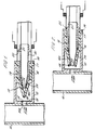
- FIG. 1 of the drawings there is shown a main tube 10 through which a liquid or gas flows and to which a subsidiary tube indicated at 11 is to be coupled.
- a generally cylindrical coupling body 12 is mounted by a clamping arrangement which will be described later on one side of the main tube.
- the coupling body 12 has an end wall 13 shaped to bear against the curved outer surface of the tube 10.
- the end wall has a small central aperture indicated at 14 and the tube has an aperture 10a in alignment with aperture 14 and formed by a piercing tool inserted through the coupling body as described in greater detail later.
- the coupling body 12 contains a "ducks bill” shaped self-closing resilient seal indicated generally at 15.
- the seal comprises a cylindrical portion 16 which engages in the cylindrical wall of the coupling body 12 and is formed with an out turned flange 17 at one end which engages around the opposite end of the coupling 12 to the end wall 13.
- the seal is held in place by an inner sleeve 18 which engages inside the tubular portion of the seal and has an out turned flange 19 which engages against the flange 17 of the seal.
- the seal 16 is formed with a portion 16a in the shape of a "ducks bill” which tapers or converges in one plane to an elongate mouth 19 where the walls of the seal meet in sealing engagement as shown in Figure 1 when not otherwise held apart.
- a probe 20 is provided at the end of the subsidiary tube 11 to be connected to the main tube 10.
- the probe has a short externally barbed end portion 21 ending an encircling shoulder 22.
- the barbed section of the probe is forced into the open end of the tube 11 until the end of the tube engages the shoulder 22.
- the main body of the probe 20 is a sliding fit in the sleeve 18 in the coupling body and is formed at its other end with a tapered or nozzle portion 23 terminating in a narrow open slit 24.
- the probe 20 inserted through the sleeve 18 into the tapered "ducks bill” portion of the seal.
- the seal is thereby opened to allow flow between the main and subsidiary tubes via the probe.
- the annular shoulder 22 on the probe engages the retaining ring 19 to limit insertion of the probe through the seal and the "ducks bill” portion of the seal seals with the outside of the probe to prevent loss of fluid around the outer side of the probe.
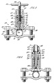
- FIG. 3 and 4 of the drawings show the mounting of the coupling body 12 to a main tube 10 in greater detail.
- the coupling body 12 is secured to the main tube by means of a saddle clamp arrangement indicated generally at 25.
- the arrangement comprises upper and lower spaced plates 36, 37 which straddle the tube 10 and are secured together by bolts 38.
- the lower plate 37 is formed with a central trough-shaped area 39 to engage directly under the tube 10.
- the upper plate 36 extends above the tube 10 and has a central flat section 40 formed with an aperture 41 to receive the coupling body 12.
- the coupling body 12 extends through the central aperture and is formed at its end 13 with an out-turned integral flange 42 which engages under the central section of the plate 40.
- the face of the end wall 13 of the coupling body is concavely recessed as indicated at 43 and a resilient seal 44 is bonded to the concave recess to engage with the outer surface of the tube 10 around the aperture in the tube.
- a cylindrical housing 45 is provided to enclose the coupling body 12 projecting from the plate 40.
- the housing is divided by an internal partition 46 to provide a downwardly open portion in which the coupling body 12 engages and an upwardly open socket 47 which will be referred to below.
- the partition has a central aperture 48.
- the lower portion of the housing is formed with an internal screw thread 49 which engages with an external screw thread on the coupling body. The housing is screwed down against the upper surface of the plate 36 to clamp the coupling body firmly to the plate with the out-turned flange 19 of sleeve 18 in the coupling body engaging the underside of the partition 46.
- the upwardly open socket 47 at the top of the housing has an internal screw thread 50 in which an externally screw threaded bush 51 is located.
- the bush has a central screw threaded hole 52 to receive the screw threaded shank 53 of a piercing tool 54.
- the tool is rotated by a thumb bar 55 at its upper end and has a reduced diameter portion 56 at its lower end which terminates in a tapered point 57 to pierce a hole in the tube 10.
- the tool 54 is screwed through the bush 51, partition 46, sleeve 18 and the "ducks bill” portion 16a of the seal which closes around and seals with a tool.
- the tool is screwed into the coupling body until the pointed end 57 engages and pierces the tube 10 to form the opening 10a in the wall of the tube as described earlier.
- This operation can be carried out when there is fluid under pressure in the tube since the seal 43 prevents loss of fluid between the tube 10 and end 13 of the connector body and the seal 16, 16a prevents loss of fluid between the connector body and tool.
- the bush 51 is extracted from the socket and replaced by the self locking tube connector 60 which may be of the type described and illustrated in UK Patent Specification No 1520742.
- the connector has a reduced diameter spigot 61 at one end formed with an external screw thread to engage in the screw threaded socket 48.
- the shoulder 62 between the main body of the connector and the spigot 61 is formed with a recess 63 in which an O-ring seal 64 is located to provide a fluid tight seal between the connector body and upper end of the cylindrical housing 45.
- the connector has an upwardly open throughway 65 in which a collet 66 is mounted to receive and lock the end part of the tube 11 in the connector.
- the throughway contains an O-ring seal 67 below the collet to seal with the outer surface of the tube 11.
- the probe 20 is mounted in the connector below the collet/seal and projects through the spigot 61 and aperture in the partition 46 into the connector body 12. The tapered end of the probe extends into the "ducks bill" portion of the seal to create the passageway through the connector body for fluid flow linking the main tube 10 to the subsidiary tube 11 as previously described.
- the arrangement provides a simple and convenient way of connecting a subsidiary tube 11 to a main tube 12 even when the latter contains fluid under pressure.
- a supply conduit for water to a piece of equipment such as a dishwasher or washing machine can readily be connected to a main water pipe without have to switch off the main water supply and drain down the system.
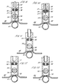
- Figures 5 to 8 show the equipment of Figures 3 and 4 in a step by step sequence of application to a main tube, piercing a hole in the main tube, replacing the piercing unit by a tube coupling and connecting a tube through the tube coupling into the tube connector to provide fluid between the main tube and subsidiary tube.
- the special nozzle 20 is omitted from the tube coupling and the tube 11 itself is pushed through the coupling and partition in the housing to the tube connector to open the seal 16/16a and thereby establish flow between the main tube and subsidiary tube.
- the self sealing tube has been described as having a "ducks bill" shaped portion where the side of the tube converge to form a sealed elongate mouth in a modified form of the seal, the walls converge in two places at right angles to one another to form, in effect, a cruciform shape at the end of the seal so that the seal opens in two mutually transverse directions.
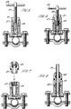
- the connector body comprises a downwardly open cylindrical enclosure 70 to engage the top of the upper clamp plate 36 above the tube 10.
- the enclosure has a internal partition 71 formed with a bore 72 and an upwardly open socket 73 above the partition.
- the lower enclosure in the cylindrical body contains a rotary spherical valve 74 having a diametrically extending through passage 75 which can be aligned with the access of the cylindrical body to open the valve as shown in Figures 9, 10 and 13 or rotated by a mechanism not shown to extend transversely of the cylindrical body to close the valve as shown in Figures 11 and 12.
- An O-ring seal 76 is mounted in the body under the partition 71 to seal the lower enclosure of the body.
- the connector body 70 is secured to the tube 10 by the saddle clamp arrangement much as described with reference to Figures 3 and 4 above.
- a piercing tool 77 is then inserted through the upper socket of the connector body, through the bore 72 in the partition 70, through the O-ring seal 76, through the valve passage 75 and finally through an opening 78 formed in the plate 36 to engage and pierce a hole in the tube 10 as depicted in Figure 9.
- valve can be rotated to the closed position as illustrated in Figure 11.
- the tool can then be fully withdrawn from the connector body.
- the subsidiary tube 11 is then inserted into the socket 73 and secured by a tube coupling such as described and illustrated in our UK Patent Specification No 1520742 and once the tube is in place, the valve 74 can be moved to the open position as shown in Figure 13 to establish flow between the tube 10 and tube 11.
Landscapes
- Engineering & Computer Science (AREA)
- General Engineering & Computer Science (AREA)
- Mechanical Engineering (AREA)
- Quick-Acting Or Multi-Walled Pipe Joints (AREA)
- Taps Or Cocks (AREA)
Priority Applications (1)
| Application Number | Priority Date | Filing Date | Title |
|---|---|---|---|
| EP99105540A EP0927851A1 (fr) | 1994-03-09 | 1995-03-08 | Raccord de tuyaux |
Applications Claiming Priority (2)
| Application Number | Priority Date | Filing Date | Title |
|---|---|---|---|
| GB9404548A GB2287294B (en) | 1994-03-09 | 1994-03-09 | Improvements in or relating to tube couplings |
| GB9404548 | 1994-03-09 |
Related Child Applications (1)
| Application Number | Title | Priority Date | Filing Date |
|---|---|---|---|
| EP99105540A Division EP0927851A1 (fr) | 1994-03-09 | 1995-03-08 | Raccord de tuyaux |
Publications (1)
| Publication Number | Publication Date |
|---|---|
| EP0671584A1 true EP0671584A1 (fr) | 1995-09-13 |
Family
ID=10751544
Family Applications (2)
| Application Number | Title | Priority Date | Filing Date |
|---|---|---|---|
| EP95301525A Withdrawn EP0671584A1 (fr) | 1994-03-09 | 1995-03-08 | Raccord de tuyaux |
| EP99105540A Withdrawn EP0927851A1 (fr) | 1994-03-09 | 1995-03-08 | Raccord de tuyaux |
Family Applications After (1)
| Application Number | Title | Priority Date | Filing Date |
|---|---|---|---|
| EP99105540A Withdrawn EP0927851A1 (fr) | 1994-03-09 | 1995-03-08 | Raccord de tuyaux |
Country Status (2)
| Country | Link |
|---|---|
| EP (2) | EP0671584A1 (fr) |
| GB (2) | GB2296950B (fr) |
Cited By (2)
| Publication number | Priority date | Publication date | Assignee | Title |
|---|---|---|---|---|
| WO2017088905A1 (fr) | 2015-11-24 | 2017-06-01 | Nec Europe Ltd. | Procédé et réseau pour gérer et orchestrer des fonctions de réseau virtuel et des applications de réseau |
| CN117533922A (zh) * | 2023-12-23 | 2024-02-09 | 上海华美电梯装饰有限公司 | 一种环保节能型电梯及其智能化制造工艺 |
Families Citing this family (1)
| Publication number | Priority date | Publication date | Assignee | Title |
|---|---|---|---|---|
| GB2369662A (en) * | 2000-11-29 | 2002-06-05 | Uponor Ltd | Tapping fitting for use with a plastics pipe |
Citations (6)
| Publication number | Priority date | Publication date | Assignee | Title |
|---|---|---|---|---|
| FR554444A (fr) * | 1923-06-11 | |||
| FR1288459A (fr) * | 1961-05-02 | 1962-03-24 | Dresser Ind | Raccord en t à poinçon de mise en service |
| FR2283382A2 (fr) * | 1974-08-27 | 1976-03-26 | Gachot Jean | Dispositif pour etablir une derivation sur une conduite et procede s'y rapportant |
| FR2348777A1 (fr) * | 1976-04-23 | 1977-11-18 | Laurent Gerard | Dispositif pour percage sans fuite de la paroi d'un tube sous pression |
| WO1983002990A1 (fr) * | 1982-02-24 | 1983-09-01 | James, Ian | Assemblage de prise d'eau d'une conduite |
| WO1991006801A1 (fr) * | 1989-10-25 | 1991-05-16 | Kai Heed | Procede et dispositif permettant le montage etanche de dispositifs sur un tube sous pression |
Family Cites Families (10)
| Publication number | Priority date | Publication date | Assignee | Title |
|---|---|---|---|---|
| GB726484A (en) * | 1953-06-30 | 1955-03-16 | Tecalemit Ltd | Couplings for use with lubrication nipples |
| US3131712A (en) * | 1960-05-12 | 1964-05-05 | Dresser Ind | Punching tee |
| US3974846A (en) * | 1972-07-14 | 1976-08-17 | Samuel Serota | Apparatus and method for gaining access to the contents of pressurized vessels and systems |
| US3905388A (en) * | 1973-07-25 | 1975-09-16 | Carl Chiarelli | Pipe tapping tool |
| SE431619B (sv) * | 1976-11-18 | 1984-02-20 | Kemp & Co Pty Ltd | Apparat for borrning av hal i ror, som star under inre overtryck |
| GB1604972A (en) * | 1978-05-31 | 1981-12-16 | Forth V P | Branch duct attachments |
| US4234006A (en) * | 1979-01-11 | 1980-11-18 | Westinghouse Electric Corp. | Method of forming an opening in the outer enclosure of a gas-insulated electrical apparatus |
| FR2553863B1 (fr) * | 1983-10-20 | 1986-06-27 | Amblard Albert | Outillage pour le percage de canalisations de fluide sous pression |
| DE3346141C1 (de) * | 1983-12-21 | 1984-12-06 | Festo KG, 7300 Esslingen | Anschlussverbindungseinheit |
| GB2199630A (en) * | 1986-12-01 | 1988-07-13 | Portex Inc | Plug |
-
1994
- 1994-03-09 GB GB9604848A patent/GB2296950B/en not_active Expired - Fee Related
- 1994-03-09 GB GB9404548A patent/GB2287294B/en not_active Expired - Fee Related
-
1995
- 1995-03-08 EP EP95301525A patent/EP0671584A1/fr not_active Withdrawn
- 1995-03-08 EP EP99105540A patent/EP0927851A1/fr not_active Withdrawn
Patent Citations (6)
| Publication number | Priority date | Publication date | Assignee | Title |
|---|---|---|---|---|
| FR554444A (fr) * | 1923-06-11 | |||
| FR1288459A (fr) * | 1961-05-02 | 1962-03-24 | Dresser Ind | Raccord en t à poinçon de mise en service |
| FR2283382A2 (fr) * | 1974-08-27 | 1976-03-26 | Gachot Jean | Dispositif pour etablir une derivation sur une conduite et procede s'y rapportant |
| FR2348777A1 (fr) * | 1976-04-23 | 1977-11-18 | Laurent Gerard | Dispositif pour percage sans fuite de la paroi d'un tube sous pression |
| WO1983002990A1 (fr) * | 1982-02-24 | 1983-09-01 | James, Ian | Assemblage de prise d'eau d'une conduite |
| WO1991006801A1 (fr) * | 1989-10-25 | 1991-05-16 | Kai Heed | Procede et dispositif permettant le montage etanche de dispositifs sur un tube sous pression |
Cited By (2)
| Publication number | Priority date | Publication date | Assignee | Title |
|---|---|---|---|---|
| WO2017088905A1 (fr) | 2015-11-24 | 2017-06-01 | Nec Europe Ltd. | Procédé et réseau pour gérer et orchestrer des fonctions de réseau virtuel et des applications de réseau |
| CN117533922A (zh) * | 2023-12-23 | 2024-02-09 | 上海华美电梯装饰有限公司 | 一种环保节能型电梯及其智能化制造工艺 |
Also Published As
| Publication number | Publication date |
|---|---|
| GB9604848D0 (en) | 1996-05-08 |
| GB2287294B (en) | 1997-05-28 |
| GB2287294A (en) | 1995-09-13 |
| GB2296950B (en) | 1997-05-28 |
| GB9404548D0 (en) | 1994-04-20 |
| GB2296950A (en) | 1996-07-17 |
| EP0927851A1 (fr) | 1999-07-07 |
Similar Documents
| Publication | Publication Date | Title |
|---|---|---|
| US5401064A (en) | Tube couplings for co-axial tubing | |
| US6347644B1 (en) | Bypass valve for water treatment system | |
| CN102791304B (zh) | 用于向设备供应高纯度液体的流体系统 | |
| US4332272A (en) | Hot tap apparatus and method | |
| US3976091A (en) | Pipe tapping tool | |
| US4598731A (en) | Valve assembly for placement over a capped, stub-out which is under water pressure in a dwelling | |
| US4331170A (en) | Hot tap apparatus and method | |
| GB2287294A (en) | Branch connections to tubes | |
| CA2147165C (fr) | Connexion de derivation | |
| US5842499A (en) | Draining device for a freeze-resistant faucet | |
| US5829474A (en) | Tubing piercing and tapping apparatus | |
| JPS5930956B2 (ja) | 破壊容易なクロ−ジヤを備えたバルブ | |
| US1803578A (en) | Sectional pipe coupling | |
| US4334334A (en) | Thread cleaning device | |
| EP0750155B1 (fr) | Té de raccordement | |
| US4116475A (en) | Direct connection co-axial fitting for injection lubricator | |
| GB2330635A (en) | Procedure for tapping into fluid pipeline under pressure | |
| JPH0512555Y2 (fr) | ||
| US3413019A (en) | Conduit connector particularly for underground sprinkler systems | |
| JPH11166683A (ja) | サービスチー継手 | |
| JPH0414698Y2 (fr) | ||
| ES248627U (es) | Dispositivo mejorado para hacer derivaciones en tuberias | |
| KR930006019Y1 (ko) | 에어호스용 연결구 | |
| EP1217287B1 (fr) | Insert de prise en charge pour collerettes de raccordement de conduites | |
| KR920001150Y1 (ko) | 상수도 분기밸브 |
Legal Events
| Date | Code | Title | Description |
|---|---|---|---|
| PUAI | Public reference made under article 153(3) epc to a published international application that has entered the european phase |
Free format text: ORIGINAL CODE: 0009012 |
|
| AK | Designated contracting states |
Kind code of ref document: A1 Designated state(s): DE ES FR IT |
|
| 17P | Request for examination filed |
Effective date: 19960122 |
|
| 17Q | First examination report despatched |
Effective date: 19970409 |
|
| STAA | Information on the status of an ep patent application or granted ep patent |
Free format text: STATUS: THE APPLICATION IS DEEMED TO BE WITHDRAWN |
|
| 18D | Application deemed to be withdrawn |
Effective date: 20000531 |