EP0671740B1 - Beschicktigungsanlage für Kassetten in einer automatischen Maschine für die Aufladung von Bändern in die Kassetten und damit durchgeführtes Verfahren zum Laden - Google Patents
Beschicktigungsanlage für Kassetten in einer automatischen Maschine für die Aufladung von Bändern in die Kassetten und damit durchgeführtes Verfahren zum Laden Download PDFInfo
- Publication number
- EP0671740B1 EP0671740B1 EP94830075A EP94830075A EP0671740B1 EP 0671740 B1 EP0671740 B1 EP 0671740B1 EP 94830075 A EP94830075 A EP 94830075A EP 94830075 A EP94830075 A EP 94830075A EP 0671740 B1 EP0671740 B1 EP 0671740B1
- Authority
- EP
- European Patent Office
- Prior art keywords
- cassette
- collapsible support
- cassettes
- processing station
- stack
- Prior art date
- Legal status (The legal status is an assumption and is not a legal conclusion. Google has not performed a legal analysis and makes no representation as to the accuracy of the status listed.)
- Expired - Lifetime
Links
Images

Classifications
-
- G—PHYSICS
- G11—INFORMATION STORAGE
- G11B—INFORMATION STORAGE BASED ON RELATIVE MOVEMENT BETWEEN RECORD CARRIER AND TRANSDUCER
- G11B23/00—Record carriers not specific to the method of recording or reproducing; Accessories, e.g. containers, specially adapted for co-operation with the recording or reproducing apparatus ; Intermediate mediums; Apparatus or processes specially adapted for their manufacture
- G11B23/02—Containers; Storing means both adapted to cooperate with the recording or reproducing means
- G11B23/113—Apparatus or processes specially adapted for the manufacture of magazines or cassettes, e.g. initial loading into container
Definitions
- the present invention relates to a cassette feeding apparatus in an automatic machine for loading tape into cassettes comprising: a loading magazine located at an overhead position relative to a processing station of said cassette loading machine and engaging a plurality of horizontally oriented cassettes disposed consecutively upon each other to form an upright stack; transferring means for picking up from said stack a cassette situated at the bottom and transferring it to said processing station while disposing the cassette according to a substantially vertical orientation.
- the cassette stack located in the loading magazine is supported by a plate-like element movable from a rest position in which it is oriented in a horizontal plane to offer a resting seat to the cassette stack, to a second position in which it is inclined at an angle of about 30° in order to cause the bottommost cassette in said stack to run from the plate-like element to a pair of guide plates extending vertically between the loading magazine and the processing station of the cassette loading machine, by which guide plates said cassette is engaged at the opposite sides thereof.
- the guide plates engage the cassette through corresponding slide grooves extending parallelly to each other according to a curvilinear extension.
- the cassette while running along said slide grooves under gravity, is gradually rotated from the inclined orientation exhibited when entering the guide plates, to a vertical orientation taken close to the lower end portions of the slide grooves.
- Such lower end portions are arranged in alignment with corresponding fitting guides provided in the processing station and designed to receive the cassette coming out of the guide plates and operatively engage it in the processing station itself.
- the cassette descent along the slide guides is assisted by a support element operatively disposed between the guide plates and vertically movable between said plates in order to cause the gradual descent of the cassette as far as it reaches the fitting guides disposed in the processing station.
- the above described apparatus may appear inappropriate for use in some situations in which the loading magazine is required to be disposed as much as possible close to the processing station of the cassette loading machine.
- the path travelled over by the cassette so that it may reach the complete orientation according to a vertical position by sliding along the guide plates makes it necessary to provide an important room between the magazine and the processing station.
- the main object of the present invention is substantially to solve the drawbacks of the known art by providing a feeding apparatus capable of operating according to a method adapted to enable a substantial reduction in space between the loading magazine and the processing station of the cassette loading machine, as well as an important reduction in the time necessary to transfer the individual cassettes from the magazine to the processing station.
- a cassette feeding apparatus in an automatic machine for loading tape into said cassettes
- said transferring means comprises: a collapsible support oscillatably engaged under the loading magazine; drive means for moving the collapsible support between a rest position in which it is substantially oriented in a horizontal plane for supporting at least one cassette disposed at the bottom in said stack, and an overturned or dropped position in which it is oriented in an angle to the horizontal plane, characterized in that the collapsible support in the over turned or dropped position is oriented in a substantially vertical plane for orienting said cassette vertically; at least one retention element is operatively engaged to the collapsible support and movable between a thrust condition in which it acts on said cassette to retain it on the collapsible support, and a release condition in which it is disengaged from said cassette; first actuating means are acting on the first retention element for selectively moving it to the thrust condition when the collapsible support
- said apparatus puts into practice a new method of feeding tape cassettes in an automatic machine for loading tape into said cassettes, comprising the steps of arranging a plurality of cassettes in a horizontal orientation one upon the other to form a stack extending vertically at an overhead position relative to a processing station of said cassette loading machine; disposing at least one cassette situated at a lowermost position in said stack onto a collapsible support arranged in a rest position in which it horizontally supports the cassette itself while the cassette is still located at the lowermost position in said stack; moving the collapsible support to a dropped position in which the cassette is oriented in an angle to the horizontal orientation, characterized by maintaining the positioning of said cassette on the collapsible support by retaining means ;
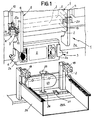
- a cassette feeding apparatus in an automatic machine for loading tape into cassettes according to the present invention has been generally identified by reference numeral 1.
- the apparatus 1 is mounted to a cassette loading machine, not shown as a whole as known per se and conventional, designed to operate sequentially on a plurality of cassettes 2 to be processed in order to wind a predetermined amount of magnetic tape into each of said cassettes.
- the magnetic tape winding operations take place at a processing station 3, not shown in detail as also known per se and conventional, exposed on a front wall 3a of the cassette loading machine.
- a pair of fitting guide pieces 4 designed to operatively engage the individual cassettes 2 at the opposite sides 2a thereof and selectively movable between a retracted position in which they are close to the front wall 3a for bringing the cassette 2 into engagement with the different members (not shown as known) of the processing station 3 for executing the tape winding operations, and an extended position in which, as shown in Figs. 2 and 3, they are spaced apart from the front wall for causing the release of a loaded cassette and the engagement of a new cassette 2 to be processed fed by the apparatus 1, as better clarified in the following.
- the cassettes 2 to be processed are stored in a loading magazine 5 disposed overhead relative to the processing station 3.
- the loading magazine 5 essentially comprises two holding plates 6 disposed vertically and jutting out from the front wall 3a.
- the cassettes 2 engaged between the holding plates 6 are oriented horizontally and disposed consecutively upon each other to form a stack 7 vertically standing between the plates themselves.
- the apparatus 1 further comprises transferring means 8 that, at each operating cycle, picks up from the stack 7 one cassette 3 situated at the bottom and transfers it to the processing station 3 where it is disposed according to a substantially vertical orientation.
- transferring means 8 that, at each operating cycle, picks up from the stack 7 one cassette 3 situated at the bottom and transfers it to the processing station 3 where it is disposed according to a substantially vertical orientation.
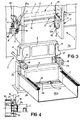
- a drive means 10 is associated with the collapsible support 9 rotatably engaged between the holding plates 6 of the magazine 5 according to an horizontal axis extending adjacent to the front wall 3a of the cassette loading machine, which drive means 10 selectively moves the collapsible support between a rest position in which it is substantially oriented in a horizontal plane for supporting at least one cassette 2 disposed at the bottom in the stack 7 and a dropped position in which it is oriented in a substantially vertical plane for orienting said cassette vertically.
- the drive means 10 essentially comprises a double acting primary cylinder operatively engaged between one of said holding plates 6 and the collapsible support 9 and operable upon command of an electronic control unit, not shown or described as known per se and at all events not of importance to the ends of the invention, which governs the operation of all members of the cassette loading machine.
- the collapsible support 9 essentially comprises a pair of arms 11 extending in cantilevered fashion from a horizontal pivot stem 12 rotatably engaged between the holding plates 6.
- Each of the arms 11 has a base portion 13 designed to offer a resting seat 13a for the cassette 2 when the collapsible support 9 is in its rest position, and a side portion 14 designed to act on one of the cassette sides 2a for guiding the fall of said cassette when the collapsible support is in the dropped position.
- At least one retention element 15 movable by first actuating means consisting of a first fluid-operated actuator 16 for example, between a thrust condition in which it acts against one side 2a of the cassette 2 to retain it on the collapsible support, and a release condition in which it is disengaged from the cassette 2 in order to make said cassette fall into the processing station 3 and more particularly into the fitting guide pieces 4 of said station when the collapsible support 9 is in the dropped position.
- the collapsible support 9 and more particularly the arms 11 associated therewith are provided to extend substantially in the extension of the fitting guide pieces 4, so that the vertically oriented cassette 2 released from the collapsible support may be securely and exactly fitted in said guide pieces arranged in the extended position.
- At least one stop element 17 movable between an operating position in which it is disposed along the falling path of the cassette 2 in the processing station 3 in order to stop said cassette when it has reached the predetermined positioning, and a non-operating position in which it is out of said cassette path in order to enable the cassette itself to fall down from the processing station 3 after it has been loaded with magnetic tape.
- two stop elements 17 are provided which essentially consist of the rods of corresponding fluid-operated actuators 18 operable upon cmmand of said electronic control unit.
- each of the stop elements 17 is at a distance from the lower end 11a exhibited by each of the arms 11 of the collapsible support 9, the amount of which substantially corresponds to, or is slightly greater than the cassette size in the vertical direction.
- the location of the loading magazine 5 as near as possible to the processing station 3 is ensured, which is to best advantage because the cassette travel path and consequently also the overall bulkiness of the apparatus is reduced, which will bring about a gain in time when the cassette 2 is transferred to the processing station.
- At least one second retention element 19 that, upon command of a third fluid-operated actuator 20 or equivalent actuating elements, can be selectively moved between a work position in which it acts in thrust relation on a cassette 2 disposed immediately on top of the cassette engaged on the collapsible support 9 in order to maintain the positioning of the stack 7 in the magazine 5, and a rest position in which it is disengaged from the cassette to let the cassettes of said stack 7 fall onto the collapsible support.
- this safety means 21 essentially consists of at least one coupling portion 22 formed in the magazine 5 and for example embodied by a shaped plate fastened to one of the holding plates 6 and exhibiting a recess 22a adapted to operatively receive the first retention element 15 when the latter is returned to the release condition after the collapsible support 9 has been brought to the corresponding rest position.
- the engagement of the first retention element 15 in the recess 22a causes the coupling portion 22 to resist the force due to the stack weight that otherwise could lead the collapsible support 9 to the dropped position.
- 23 denotes a pusher element that in a manner known per se is horizontally movable below the loading station 3 in order to make the cassettes 2 move sequentially forward along a collection element 24 as said cassettes are released from the processing station itself.
- a support disc 25 is also provided.
- Said disc 25 is vertically movable, upon command of an auxiliary actuator not shown in the figures, between a raised position in which it receives and supports the cassette 2 coming out of the fitting guide pieces 4 and a lowered position in which it is disposed substantially flush with a base surface 24a of the collection element 24 in order to deposit the cassette thereon.
- a transverse slot 26 through which possible faulty cassettes 2 are discharged from the collection element 24.
- one or more closing elements 27 consisting of blocks connected to corresponding fluid-operated actuators, selectively movable between a closing position in which they close off the cassette exit through the slot 26 in order to enable transferring of said cassettes along the collection element 24, and a opening condition in which they completely clear the slot in order to enable faulty cassettes to be discharged therethrough.
- the operating cycle of the apparatus in question described above mainly as regards structure, is as follows.
- the collapsible support 9 is held in the rest position upon the action of the primary cylinder 10, so that the bottommost cassette 2 in the stack 7 arranged in the loading magazine 5 is suitably engaged to the arms 11 of the collapsible support itself.
- the fitting guide pieces 4 are moved away from the front wall 3a in order to cause the disengagement of the cassette from the processing station 3.
- the cassette 2 loaded with magnetic tape will be brought to rest on the disc 25 previously disposed to the raised position to be then put down onto the base surface 24a of the collection element 24, upon lowering of the disc.
- the first retention element 15 is brought to the thrust condition, and the collapsible support 9 is moved to the dropped position in order to orient the cassette 2 engaged thereto vertically.
- the second retention element 19 previously borught to the work position upon command of the corresponding actuator 20, conveniently retains the cassette stack 7 preventing the cassettes from falling out of the magazine 5.
- the first retention element 15 is brought to the release condition to cause the cassette 2 carried by the support to fall vertically into the fitting guide pieces 4, stopping against the stop elements 17 previously disposed in the operating position.
- the cassette 2 is completely disengaged from the collapsible support 9, which support therefore can be returned to the rest condition, upon disposition of the first retention element 15 to the thrust condition in order to prevent the latter from interferring with the coupling portion 22 when the collapsible support carries out a raising movement.
- the first retention element 15 is brought again to the release condition and is fitted into the recess 22a while the second retention element 19 is brought to the rest position to cause lowering of the stack 7 between the holding plates 6 and consequent engagement of a new cassette 2 on the collapsible support 9.
- fitting guide pieces 4 are moved close to the front wall 3a to operatively engage the cassette 2 in the processing station 3, thereby starting a new magnetic tape winding cycle.
- the present invention attains the intended purposes.
- the apparatus in question is in fact conceived in such a manner that it enables the positioning of the magazine 5 very close to the processing station 3, which involves an important reduction in bulkiness as compared to the apparatus of the known art as well as a drastic reduction in the time necessary to transfer the individual cassettes from the magazine to the processing station.
- the invention becomes of much simpler construction as compared to the feeding apparatus of the known art, since the guide plates and movement means connected thereto for causing the gradual orientation of the cassette from an inclined position to a vertical position (as required for insertion in the processing station) are eliminated.
- the apparatus in question described with specific reference to feeding of VHS video cassettes to machines for winding tape thereinto can be adapted to carry out, in the same manner as described above, feeding of cassettes of different types as well as box-shaped elements, such as tape cassette or compact-disc casings, to machines for executing other processings provided in the production cycle of articles of the type in question.
Landscapes
- Replacement Of Web Rolls (AREA)
- Automatic Assembly (AREA)
- Folding Of Thin Sheet-Like Materials, Special Discharging Devices, And Others (AREA)
Claims (11)
- Beschickungsanlage für Kassetten in einer automatischen Maschine für die Aufladung von Bändern in die Kassetten,
umfassend:dadurch gekennzeichnet, daßein Lademagazin (5), das in einer oberhalb einer Arbeitsstation (3) der automatischen Maschine für die Aufladung angeordnet ist und eine Vielzahl von Kassetten (2) ergreift, die horizontal ausgerichtet und aufeinander zur Bildung eines senkrechten Stapels (7) angeordnet sind;Übergabemittel (8) zur Entnahme einer unterhalb des Stapels (7) angeordneten Kassette (2) und deren Übergabe an die Arbeitsstation (3), wobei die Kassette selbst gemäß einer im wesentlichen senkrechten Ausrichtung angeordnet wird, wobei die Übergabemittel (8) umfassen:einen unterhalb des Lademagazins (5) verschwenkbaren in Eingriff stehenden, abschlagbaren Halter (9);Steuermittel (10) zur Verstellung des abschlagbaren Halters zwischen einer Ruhestellung, in der er im wesentlichen gemäß einer horizontalen Ebene zur Abstützung mindestens der unterhalb des Stapels (7) liegenden Kassette (2) ausgerichtet ist, und einer abgekippten bzw. abgeschlagenen Position, in der er gemäß einem Winkel gegenüber der horizontalen Ebene ausgerichtet ist,der abschlagbare Halter in der abgekippten bzw. abgeschlagenen Position gemäß einer im wesentlichen senkrechten Ebene ausgerichtet ist, um die Kassette (2) senkrecht auszurichten;mindestens ein erstes Klemmelement (15) am abschlagbaren Halter wirksam in Eingriff steht und zwischen einem Schubzustand, in der er auf die Kassette einwirkt, um sie am abschlagbaren Halter selbst zurückzuhalten, und einem Freigabezustand beweglich ist, in der es von der Kassette befreit ist;erste Betätigungsmittel (16) auf das erste Klemmelement (15) wirken, um es wahlweise im Schubzustand, wenn der abschlagbare Halter sich in Ruhestellung befindet, und im Freigabezustand zu verstellen, wenn sich der abschlagbare Halter in der abgeschlagenen Position befindet, um die Kassette in die Arbeitsstation senkrecht fallen zu lassen. - Anlage nach Anspruch 1, dadurch gekennzeichnet, daß sie überdies Sicherheitsmittel (21) umfaßt, um am Lademagazin (5) den abschlagbaren Halter (9) in seiner Ruheposition starr festzulegen.
- Anlage nach Anspruch 2, dadurch gekennzeichnet, daß die Sicherheitsmittel (21) einen Einsteckabschnitt (22) umfassen, der im Lademagazin (5) ausgenommen ist und eine Hinterschneidung (22a) umfaßt, die zur Aufnahme des ersten Klemmelementes (15) bereitgestellt ist, wenn dieses letztere in den Freigabezustand zurückgeführt wird, nachdem der Halter (9) in die Ruhestellung gebracht wurde.
- Anlage nach Anspruch 1, dadurch gekennzeichnet, daß sie überdies mindestens ein Arretierelement (17) umfaßt, das zwischen einer Arbeitsstellung, in der es sich auf der Fallbahn der Kassette (2) in der Arbeitsstation (3) zum Anhalten der Kassette selbst gemäß einer vorgegebenen Positionierung angeordnet ist, und einer Stellung außer Wirkung beweglich ist, in der es sich außerhalb der Fallbahn befindet, um die Kassette (2) aus der Arbeitsstation (3) fallen zu lassen.
- Anlage nach Anspruch 4, dadurch gekennzeichnet, daß, wenn sich der abschlagbare (9) Halter in der abgeschlagenen Position befindet, das Arretierelement von unterem Ende (11a) des abschlagbaren Halters selbst um ein Maß beabstandet ist, das im wesentlichen der Abmessung der Kassette (2) in senkrechter Richtung entspricht.
- Anlage nach Anspruch 1, dadurch gekennzeichnet, daß in der abgeschlagenen Position der abschlagbare Halter (9) sich im wesentlichen auf dem Fortsatz von Einrückführungen (4) erstreckt, die der Arbeitsstation (3) zugeordnet und dazu bereitgestellt sind, wirksam die Kassette (2) auf seitlich abgewandten Abschnitten zu ergreifen.
- Anlage nach Anspruch 1, dadurch gekennzeichnet, daß der abschlagbare Halter (9) ein Paar von Armen (11) umfaßt, die sich auskragend von einem horizontalen Anlenkbolzen (12) erstrecken, der gegenüber dem Lademagazin (5) drehbar in Eingriff steht, wobei jeder dieser Arme (11) einen Basisabschnitt (13), der dazu bereitgestellt ist, eine Anlageaufnahme (13a) für die Kassette (2) zu bilden, sobald der abschlagbare Halter (9) sich in der Ruhestellung befindet, und einen seitlichen Abschnitt (14) umfaßt, der dazu bereitgestellt ist, längs einer Flanke (2a) der Kassette (2) zu wirken, um deren Fall zu führen, sobald sich der abschlagbare Halter (9) in der abgeschlagenen Position befindet.
- Anlage nach Anspruch 1, dadurch gekennzeichnet, daß sie überdies umfaßt:mindestens ein zweites Klemmelement (19), das am Lademagazin (5) wirksam angreift und zwischen einer Arbeitsstellung, in der es auf die unmittelbar oberhalb der am abschlagbaren Halter (9) in Eingriff stehenden Kassette (2) liegenden Kassette (2) wirkt, um die Positionierung des Stapels (7) im Magazin selbst zu blockieren, und einer Ruhestellung beweglich ist, in der es von der unmittelbar darüberliegenden Kassette befreit ist, um die Kassette des Stapels (7) auf den abschlagbaren Halter (9) fallen zu lassen;Aktiviermittel (20), die dem zweiten Klemmelement (19) zugeordnet sind, um es wahlweise in die Arbeitsstellung, sobald sich der abschlagbare Halter (9) in die abgeschlagene Position bewegt, und in die Ruhestellung zu bringen, sobald der abschlagbare Halter selbst in die Ruhestellung zurückgebracht wurde.
- Verfahren zur Beschickung von Bandkassetten in einer automatischen Maschine für die Aufladung von Bändern in die Kassetten, umfassend die Arbeitsschritte:gekennzeichnet durchBereitstellung einer Vielzahl von Kassetten (2) gemäß einer horizontalen Ausrichtung und gegenseitig aufeinander liegend zur Bildung eines Stapels (7), der sich senkrecht in einer oberhalb einer Arbeitsstation (3) der Maschine zum Laden senkrecht erstreckt,Anordnung mindestens einer unterhalb des Stapels (7) angeordneten Kassette (2) in Auflage auf einen abschlagbaren Halter (9), der in einer Ruhestellung bereitgestellt ist, in der er die Kassette selbst horizontal abstützt, während die Kassette sich noch in der untersten Stellung in diesem Stapel befindet;Anordnung des abschlagbaren Halters (9) in einer abgeschlagenen Stellung, in der die Kassette gemäß einem Winkel gegenüber der horizontalen Ausrichtung ausgerichtet ist,Blockierung der Positionierung der Kassette (2) auf dem abschlagbaren Halter (9) durch Klemmittel (15);wobei die abgeschlagene Stellung des abschlagbaren Halters eine Stellung ist, in der die auf ihm geklemmte Kassette gemäß einer im wesentlichen senkrechten Ebene ausgerichtet ist;Freigabe der Kassette (2) vom abschlagbaren Halter (9), um sie senkrecht in die Arbeitsstation (3) fallen zu lassen.
- Verfahren nach Anspruch 9, dadurch gekennzeichnet, daß in Begleitung mit dem Arbeitsschritt des Umkippens bzw. des Abschlagens überdies der Arbeitsschritt durchgeführt wird, bei dem die Positionierung der Kassetten (2) des Stapels (7) blockiert wird, die oberhalb der auf dem abschlagbaren Halter (9) blockierten Kassette liegen.
- Verfahren nach Anspruch 9, dadurch gekennzeichnet, daß es überdies den Arbeitsschritt umfaßt, bei dem der Fall der Kassette (2) in die Arbeitsstation (3) unterbrochen wird, um die Kassette selbst gemäß einer vorgegebenen Positionierung zu blockieren.
Priority Applications (5)
| Application Number | Priority Date | Filing Date | Title |
|---|---|---|---|
| AT94830075T ATE180354T1 (de) | 1994-02-18 | 1994-02-18 | Beschicktigungsanlage für kassetten in einer automatischen maschine für die aufladung von bändern in die kassetten und damit durchgeführtes verfahren zum laden |
| EP94830075A EP0671740B1 (de) | 1994-02-18 | 1994-02-18 | Beschicktigungsanlage für Kassetten in einer automatischen Maschine für die Aufladung von Bändern in die Kassetten und damit durchgeführtes Verfahren zum Laden |
| DE69418594T DE69418594T2 (de) | 1994-02-18 | 1994-02-18 | Beschicktigungsanlage für Kassetten in einer automatischen Maschine für die Aufladung von Bändern in die Kassetten und damit durchgeführtes Verfahren zum Laden |
| ES94830075T ES2133520T3 (es) | 1994-02-18 | 1994-02-18 | Aparato de alimentacion de cassettes en una maquina para la carga automatica de cintas en cassettes y metodo de carga realizado por esta. |
| US08/745,068 US5722565A (en) | 1994-02-18 | 1996-11-07 | Cassette feeding system and method |
Applications Claiming Priority (1)
| Application Number | Priority Date | Filing Date | Title |
|---|---|---|---|
| EP94830075A EP0671740B1 (de) | 1994-02-18 | 1994-02-18 | Beschicktigungsanlage für Kassetten in einer automatischen Maschine für die Aufladung von Bändern in die Kassetten und damit durchgeführtes Verfahren zum Laden |
Publications (2)
| Publication Number | Publication Date |
|---|---|
| EP0671740A1 EP0671740A1 (de) | 1995-09-13 |
| EP0671740B1 true EP0671740B1 (de) | 1999-05-19 |
Family
ID=8218387
Family Applications (1)
| Application Number | Title | Priority Date | Filing Date |
|---|---|---|---|
| EP94830075A Expired - Lifetime EP0671740B1 (de) | 1994-02-18 | 1994-02-18 | Beschicktigungsanlage für Kassetten in einer automatischen Maschine für die Aufladung von Bändern in die Kassetten und damit durchgeführtes Verfahren zum Laden |
Country Status (4)
| Country | Link |
|---|---|
| EP (1) | EP0671740B1 (de) |
| AT (1) | ATE180354T1 (de) |
| DE (1) | DE69418594T2 (de) |
| ES (1) | ES2133520T3 (de) |
Families Citing this family (1)
| Publication number | Priority date | Publication date | Assignee | Title |
|---|---|---|---|---|
| JP3958884B2 (ja) | 1998-09-11 | 2007-08-15 | 株式会社林原生物化学研究所 | 非還元性糖質生成酵素及びトレハロース遊離酵素ならびに該酵素を用いる糖質の製造方法 |
Family Cites Families (5)
| Publication number | Priority date | Publication date | Assignee | Title |
|---|---|---|---|---|
| US3964100A (en) * | 1972-10-10 | 1976-06-15 | Programming Technologies, Inc. | Automatic tape loading apparatus for cassettes and the like |
| US3814343A (en) * | 1972-10-10 | 1974-06-04 | Programming Technologies Inc | Automatic tape loading apparatus for cassettes and the like |
| IT1185421B (it) * | 1985-10-11 | 1987-11-12 | Telefunken Robotecnica Srl | Dispositivo automatico per l'orientamento e l'alimentazione di cassette per nastro magnetico |
| IT1202663B (it) * | 1987-03-10 | 1989-02-09 | Luciano Perego | Apparecchiatura e procedimento per l'avvolgimento di nastri in cassette,particolarmente per nastri magnetici |
| IT1230946B (it) * | 1989-06-28 | 1991-11-08 | Discmatic Srl | Dispositivo di erogazione di cassette per il caricamento di nastro magnetico. |
-
1994
- 1994-02-18 EP EP94830075A patent/EP0671740B1/de not_active Expired - Lifetime
- 1994-02-18 ES ES94830075T patent/ES2133520T3/es not_active Expired - Lifetime
- 1994-02-18 AT AT94830075T patent/ATE180354T1/de not_active IP Right Cessation
- 1994-02-18 DE DE69418594T patent/DE69418594T2/de not_active Expired - Fee Related
Also Published As
| Publication number | Publication date |
|---|---|
| DE69418594T2 (de) | 1999-09-16 |
| DE69418594D1 (de) | 1999-06-24 |
| EP0671740A1 (de) | 1995-09-13 |
| ES2133520T3 (es) | 1999-09-16 |
| ATE180354T1 (de) | 1999-06-15 |
Similar Documents
| Publication | Publication Date | Title |
|---|---|---|
| US3852819A (en) | Automatic changer for cassette player-recorder | |
| US4918548A (en) | Cartridge loader | |
| US6222800B1 (en) | Autoload disk copier system | |
| US5312060A (en) | Device for feeding reels into a packaging machine | |
| US8015781B2 (en) | Box loader | |
| GB1591254A (en) | Multiple cassette record and/or playback apparatus and systems incorporating the same | |
| GB1591253A (en) | Multiple cassette record and/or playback apparatus incorporating a cassette eject device | |
| JPH06127672A (ja) | トレイの移送方法とその装置 | |
| JPS63298883A (ja) | カセット巻取装置及びその制御方法 | |
| EP0568761B1 (de) | Bandkassettenzufuhreinheit für automatischen Vorrichtungen | |
| US5598949A (en) | Cassette feeding system and method | |
| EP0671740A1 (de) | Beschicktigungsanlage für Kassetten in eine automatischen Maschine für die Aufladung von Bändern in die Kassetten und damit durchgeführtes Verfahren zum Laden | |
| US20090266037A1 (en) | Box loader | |
| EP0405046B1 (de) | Kassettenzuführsystem | |
| US5785489A (en) | Case-feeding unit in an automatic apparatus for packaging manufactured articles into cases and automatic case-feeding method relating to same | |
| EP0376895B1 (de) | Kontinuierlicher Zufuhr- und Entladefluss durch ein Kassettenladegerät und System dafür | |
| US5718557A (en) | Apparatus and method for putting cassettes into trays | |
| US5356092A (en) | Reduced size tape loading module | |
| EP0655400B1 (de) | Vorrichtung und Verfahren für das geordnete Einbringen von Magnetbandkassetten in entsprechende trogförmige Behälter | |
| JP7761680B2 (ja) | リール装填装置 | |
| JP3479371B2 (ja) | 苗補給装置 | |
| US5397074A (en) | Apparatus and method for threading tape wound on a reel through a cassette loading machine | |
| JP2501623B2 (ja) | タブレットストッカ | |
| GB2061892A (en) | Cassette correlator | |
| AU6643194A (en) | System and method for accessing information on stored optical discs |
Legal Events
| Date | Code | Title | Description |
|---|---|---|---|
| PUAI | Public reference made under article 153(3) epc to a published international application that has entered the european phase |
Free format text: ORIGINAL CODE: 0009012 |
|
| 17P | Request for examination filed |
Effective date: 19941005 |
|
| AK | Designated contracting states |
Kind code of ref document: A1 Designated state(s): AT BE CH DE DK ES FR GB GR IE IT LI LU MC NL PT SE |
|
| GRAG | Despatch of communication of intention to grant |
Free format text: ORIGINAL CODE: EPIDOS AGRA |
|
| GRAG | Despatch of communication of intention to grant |
Free format text: ORIGINAL CODE: EPIDOS AGRA |
|
| GRAH | Despatch of communication of intention to grant a patent |
Free format text: ORIGINAL CODE: EPIDOS IGRA |
|
| GRAH | Despatch of communication of intention to grant a patent |
Free format text: ORIGINAL CODE: EPIDOS IGRA |
|
| 17Q | First examination report despatched |
Effective date: 19981022 |
|
| GRAA | (expected) grant |
Free format text: ORIGINAL CODE: 0009210 |
|
| ITF | It: translation for a ep patent filed | ||
| AK | Designated contracting states |
Kind code of ref document: B1 Designated state(s): AT BE CH DE DK ES FR GB GR IE IT LI LU MC NL PT SE |
|
| PG25 | Lapsed in a contracting state [announced via postgrant information from national office to epo] |
Ref country code: SE Free format text: THE PATENT HAS BEEN ANNULLED BY A DECISION OF A NATIONAL AUTHORITY Effective date: 19990519 Ref country code: NL Free format text: LAPSE BECAUSE OF FAILURE TO SUBMIT A TRANSLATION OF THE DESCRIPTION OR TO PAY THE FEE WITHIN THE PRESCRIBED TIME-LIMIT Effective date: 19990519 Ref country code: LI Free format text: LAPSE BECAUSE OF FAILURE TO SUBMIT A TRANSLATION OF THE DESCRIPTION OR TO PAY THE FEE WITHIN THE PRESCRIBED TIME-LIMIT Effective date: 19990519 Ref country code: GR Free format text: LAPSE BECAUSE OF NON-PAYMENT OF DUE FEES Effective date: 19990519 Ref country code: CH Free format text: LAPSE BECAUSE OF FAILURE TO SUBMIT A TRANSLATION OF THE DESCRIPTION OR TO PAY THE FEE WITHIN THE PRESCRIBED TIME-LIMIT Effective date: 19990519 Ref country code: BE Free format text: LAPSE BECAUSE OF FAILURE TO SUBMIT A TRANSLATION OF THE DESCRIPTION OR TO PAY THE FEE WITHIN THE PRESCRIBED TIME-LIMIT Effective date: 19990519 Ref country code: AT Free format text: LAPSE BECAUSE OF FAILURE TO SUBMIT A TRANSLATION OF THE DESCRIPTION OR TO PAY THE FEE WITHIN THE PRESCRIBED TIME-LIMIT Effective date: 19990519 |
|
| REF | Corresponds to: |
Ref document number: 180354 Country of ref document: AT Date of ref document: 19990615 Kind code of ref document: T |
|
| REG | Reference to a national code |
Ref country code: CH Ref legal event code: EP |
|
| REG | Reference to a national code |
Ref country code: IE Ref legal event code: FG4D |
|
| ET | Fr: translation filed | ||
| REF | Corresponds to: |
Ref document number: 69418594 Country of ref document: DE Date of ref document: 19990624 |
|
| PG25 | Lapsed in a contracting state [announced via postgrant information from national office to epo] |
Ref country code: PT Free format text: LAPSE BECAUSE OF FAILURE TO SUBMIT A TRANSLATION OF THE DESCRIPTION OR TO PAY THE FEE WITHIN THE PRESCRIBED TIME-LIMIT Effective date: 19990819 Ref country code: DK Free format text: LAPSE BECAUSE OF FAILURE TO SUBMIT A TRANSLATION OF THE DESCRIPTION OR TO PAY THE FEE WITHIN THE PRESCRIBED TIME-LIMIT Effective date: 19990819 |
|
| REG | Reference to a national code |
Ref country code: ES Ref legal event code: FG2A Ref document number: 2133520 Country of ref document: ES Kind code of ref document: T3 |
|
| REG | Reference to a national code |
Ref country code: CH Ref legal event code: PL |
|
| PGFP | Annual fee paid to national office [announced via postgrant information from national office to epo] |
Ref country code: FR Payment date: 20000210 Year of fee payment: 7 |
|
| PG25 | Lapsed in a contracting state [announced via postgrant information from national office to epo] |
Ref country code: LU Free format text: LAPSE BECAUSE OF NON-PAYMENT OF DUE FEES Effective date: 20000218 Ref country code: IE Free format text: LAPSE BECAUSE OF NON-PAYMENT OF DUE FEES Effective date: 20000218 |
|
| PGFP | Annual fee paid to national office [announced via postgrant information from national office to epo] |
Ref country code: ES Payment date: 20000228 Year of fee payment: 7 |
|
| PG25 | Lapsed in a contracting state [announced via postgrant information from national office to epo] |
Ref country code: MC Free format text: THE PATENT HAS BEEN ANNULLED BY A DECISION OF A NATIONAL AUTHORITY Effective date: 20000229 |
|
| PLBE | No opposition filed within time limit |
Free format text: ORIGINAL CODE: 0009261 |
|
| STAA | Information on the status of an ep patent application or granted ep patent |
Free format text: STATUS: NO OPPOSITION FILED WITHIN TIME LIMIT |
|
| 26N | No opposition filed | ||
| REG | Reference to a national code |
Ref country code: IE Ref legal event code: MM4A |
|
| PGFP | Annual fee paid to national office [announced via postgrant information from national office to epo] |
Ref country code: GB Payment date: 20010214 Year of fee payment: 8 |
|
| PG25 | Lapsed in a contracting state [announced via postgrant information from national office to epo] |
Ref country code: ES Free format text: LAPSE BECAUSE OF NON-PAYMENT OF DUE FEES Effective date: 20010219 |
|
| PG25 | Lapsed in a contracting state [announced via postgrant information from national office to epo] |
Ref country code: FR Free format text: LAPSE BECAUSE OF NON-PAYMENT OF DUE FEES Effective date: 20011031 |
|
| REG | Reference to a national code |
Ref country code: FR Ref legal event code: ST |
|
| REG | Reference to a national code |
Ref country code: GB Ref legal event code: IF02 |
|
| PG25 | Lapsed in a contracting state [announced via postgrant information from national office to epo] |
Ref country code: GB Free format text: LAPSE BECAUSE OF NON-PAYMENT OF DUE FEES Effective date: 20020218 |
|
| GBPC | Gb: european patent ceased through non-payment of renewal fee |
Effective date: 20020218 |
|
| REG | Reference to a national code |
Ref country code: ES Ref legal event code: FD2A Effective date: 20021016 |
|
| PGFP | Annual fee paid to national office [announced via postgrant information from national office to epo] |
Ref country code: DE Payment date: 20030227 Year of fee payment: 10 |
|
| PG25 | Lapsed in a contracting state [announced via postgrant information from national office to epo] |
Ref country code: DE Free format text: LAPSE BECAUSE OF NON-PAYMENT OF DUE FEES Effective date: 20040901 |
|
| PG25 | Lapsed in a contracting state [announced via postgrant information from national office to epo] |
Ref country code: IT Free format text: LAPSE BECAUSE OF NON-PAYMENT OF DUE FEES;WARNING: LAPSES OF ITALIAN PATENTS WITH EFFECTIVE DATE BEFORE 2007 MAY HAVE OCCURRED AT ANY TIME BEFORE 2007. THE CORRECT EFFECTIVE DATE MAY BE DIFFERENT FROM THE ONE RECORDED. Effective date: 20050218 |