EP0672108B1 - Verfahren und Vorrichtung zum Herstellen eines fermentierten Getränks. - Google Patents
Verfahren und Vorrichtung zum Herstellen eines fermentierten Getränks. Download PDFInfo
- Publication number
- EP0672108B1 EP0672108B1 EP92908733A EP92908733A EP0672108B1 EP 0672108 B1 EP0672108 B1 EP 0672108B1 EP 92908733 A EP92908733 A EP 92908733A EP 92908733 A EP92908733 A EP 92908733A EP 0672108 B1 EP0672108 B1 EP 0672108B1
- Authority
- EP
- European Patent Office
- Prior art keywords
- pressure
- assembly
- bath
- chamber
- vessel
- Prior art date
- Legal status (The legal status is an assumption and is not a legal conclusion. Google has not performed a legal analysis and makes no representation as to the accuracy of the status listed.)
- Expired - Lifetime
Links
Images



Classifications
-
- C—CHEMISTRY; METALLURGY
- C12—BIOCHEMISTRY; BEER; SPIRITS; WINE; VINEGAR; MICROBIOLOGY; ENZYMOLOGY; MUTATION OR GENETIC ENGINEERING
- C12C—BEER; PREPARATION OF BEER BY FERMENTATION; PREPARATION OF MALT FOR MAKING BEER; PREPARATION OF HOPS FOR MAKING BEER
- C12C13/00—Brewing devices, not covered by a single group of C12C1/00 - C12C12/04
- C12C13/10—Home brew equipment
-
- B—PERFORMING OPERATIONS; TRANSPORTING
- B01—PHYSICAL OR CHEMICAL PROCESSES OR APPARATUS IN GENERAL
- B01F—MIXING, e.g. DISSOLVING, EMULSIFYING OR DISPERSING
- B01F23/00—Mixing according to the phases to be mixed, e.g. dispersing or emulsifying
- B01F23/20—Mixing gases with liquids
- B01F23/23—Mixing gases with liquids by introducing gases into liquid media, e.g. for producing aerated liquids
- B01F23/236—Mixing gases with liquids by introducing gases into liquid media, e.g. for producing aerated liquids specially adapted for aerating or carbonating beverages
- B01F23/2362—Mixing gases with liquids by introducing gases into liquid media, e.g. for producing aerated liquids specially adapted for aerating or carbonating beverages for aerating or carbonating within receptacles or tanks, e.g. distribution machines
-
- B—PERFORMING OPERATIONS; TRANSPORTING
- B67—OPENING, CLOSING OR CLEANING BOTTLES, JARS OR SIMILAR CONTAINERS; LIQUID HANDLING
- B67D—DISPENSING, DELIVERING OR TRANSFERRING LIQUIDS, NOT OTHERWISE PROVIDED FOR
- B67D1/00—Apparatus or devices for dispensing beverages on draught
- B67D1/06—Mountings or arrangements of dispensing apparatus in or on shop or bar counters
-
- B—PERFORMING OPERATIONS; TRANSPORTING
- B67—OPENING, CLOSING OR CLEANING BOTTLES, JARS OR SIMILAR CONTAINERS; LIQUID HANDLING
- B67D—DISPENSING, DELIVERING OR TRANSFERRING LIQUIDS, NOT OTHERWISE PROVIDED FOR
- B67D1/00—Apparatus or devices for dispensing beverages on draught
- B67D1/08—Details
- B67D1/12—Flow or pressure control devices or systems, e.g. valves, gas pressure control, level control in storage containers
- B67D1/125—Safety means, e.g. over-pressure valves
-
- C—CHEMISTRY; METALLURGY
- C12—BIOCHEMISTRY; BEER; SPIRITS; WINE; VINEGAR; MICROBIOLOGY; ENZYMOLOGY; MUTATION OR GENETIC ENGINEERING
- C12C—BEER; PREPARATION OF BEER BY FERMENTATION; PREPARATION OF MALT FOR MAKING BEER; PREPARATION OF HOPS FOR MAKING BEER
- C12C11/00—Fermentation processes for beer
- C12C11/003—Fermentation of beerwort
-
- C—CHEMISTRY; METALLURGY
- C12—BIOCHEMISTRY; BEER; SPIRITS; WINE; VINEGAR; MICROBIOLOGY; ENZYMOLOGY; MUTATION OR GENETIC ENGINEERING
- C12C—BEER; PREPARATION OF BEER BY FERMENTATION; PREPARATION OF MALT FOR MAKING BEER; PREPARATION OF HOPS FOR MAKING BEER
- C12C11/00—Fermentation processes for beer
- C12C11/003—Fermentation of beerwort
- C12C11/006—Fermentation tanks therefor
-
- Y—GENERAL TAGGING OF NEW TECHNOLOGICAL DEVELOPMENTS; GENERAL TAGGING OF CROSS-SECTIONAL TECHNOLOGIES SPANNING OVER SEVERAL SECTIONS OF THE IPC; TECHNICAL SUBJECTS COVERED BY FORMER USPC CROSS-REFERENCE ART COLLECTIONS [XRACs] AND DIGESTS
- Y10—TECHNICAL SUBJECTS COVERED BY FORMER USPC
- Y10S—TECHNICAL SUBJECTS COVERED BY FORMER USPC CROSS-REFERENCE ART COLLECTIONS [XRACs] AND DIGESTS
- Y10S261/00—Gas and liquid contact apparatus
- Y10S261/07—Carbonators
-
- Y—GENERAL TAGGING OF NEW TECHNOLOGICAL DEVELOPMENTS; GENERAL TAGGING OF CROSS-SECTIONAL TECHNOLOGIES SPANNING OVER SEVERAL SECTIONS OF THE IPC; TECHNICAL SUBJECTS COVERED BY FORMER USPC CROSS-REFERENCE ART COLLECTIONS [XRACs] AND DIGESTS
- Y10—TECHNICAL SUBJECTS COVERED BY FORMER USPC
- Y10T—TECHNICAL SUBJECTS COVERED BY FORMER US CLASSIFICATION
- Y10T137/00—Fluid handling
- Y10T137/2931—Diverse fluid containing pressure systems
- Y10T137/2984—Foam control in gas charged liquids
-
- Y—GENERAL TAGGING OF NEW TECHNOLOGICAL DEVELOPMENTS; GENERAL TAGGING OF CROSS-SECTIONAL TECHNOLOGIES SPANNING OVER SEVERAL SECTIONS OF THE IPC; TECHNICAL SUBJECTS COVERED BY FORMER USPC CROSS-REFERENCE ART COLLECTIONS [XRACs] AND DIGESTS
- Y10—TECHNICAL SUBJECTS COVERED BY FORMER USPC
- Y10T—TECHNICAL SUBJECTS COVERED BY FORMER US CLASSIFICATION
- Y10T137/00—Fluid handling
- Y10T137/8593—Systems
- Y10T137/86236—Tank with movable or adjustable outlet or overflow pipe
- Y10T137/86252—Float-supported outlet
Definitions
- This invention relates to a method and apparatus for making a fermented beverage, such as beer. More particularly, the invention relates to making a fermented beverage in a pressurized or closed environment for the homebrewing trade.
- Beer has been made by various techniques and using various apparatuses for many years, as is well known. In general, these techniques can be divided into commercial and homemaking methods. Commercial techniques produce consistent quality beer of various types but the price of such beer is high due to taxes and the like which are placed on the beer.
- an assembly for fermenting a fermentable liquid mixture comprising:
- a methcd of producing a beer in the apparatus and under chilled conditions comprising:
- the entrance port is disposed in a float for allowing entry of liquid under pressure to tube extending from said entrance port to the spigot for transporting said liquid from said float to said spigot.
- the dispenser comprises a housing operable to hold a gas cartridge, a cap operable to be connected to said housing, a first chamber in said housing operable to hold pressure at a first pressure and a second chamber downstream of said first chamber operable to hold pressure at a second pressure, said second pressure being lower than said first pressure, a piston to allow communicaticn between said first and second chambers, said second chamber being in communication with a pressure vessel.
- the apparatus for producing a fermented beverage further comprises defoaming means which is located between said relief valve means and the interior of the vessel to counteract foam produced during said fermentation process from coming into contact with the pressure relief valve means.
- the pressure relief valve means comprises a valve seat on a support member and a spring loaded valve member on said seat which valve member is adapted to open when the pressure in the vessel exceeds a first predetermined value, the seat being capable of movement relative to said support member to vent the vessel to the atmosphere when the pressure in the vessel exceeds a second predetermined value, which is higher than said first predetermined value.
- a method of producing a fermented beverage comprising the steps of fermenting beverage producing ingredients in the presence of a yeast and a defoaming agent, which defoaming agent is screened from the fermented beverage produced by the fermentation process.
- the beer producing apparatus is illustrated generally at 10 in Figure 1. It comprises a pressure vessel, generally illustrated at 11, and a base member 12.
- the pressure vessel 11 comprises separable portions in the form of two identical and separable case halves, the upper case half 13 and the lower case half 14, made from a PET (polyethylene terephthalate) and being transparent.
- PET polyethylene terephthalate
- the main seal 20 includes divergent projections which extend inwardly to the chamber.
- Rails 15,16 extend completely around the periphery of the upper and lower case halves 13,14, respectively.
- a spigot generally illustrated at 23 is carried by the lower case half 14.
- the spigot 23 comprises the dispenser part 24, a first rubber washer 30 mounted between the outside of the lower case half 14 and the spigot 23, a second rubber washer 25 mounted between the inside of the lower case half 14 and a spigot retainer nut 31 which is threadedly engaged with a spigot 23 through the lower case half 14.
- a tube 72 extends from the spigot 23 as will be described in greater detail hereafter.
- the dispenser part 24 of the spigot 23 is inserted through a hole 32 positioned in the lower case half 14 with the washer 30 mounted outside the pressure vessel 11 and the washer 25 between the spigot retainer nut 31 and the inside of the lower case half 14. The spigot retainer then is retained in position in the lower case half 14.
- a top cap assembly is generally illustrated at 33. It comprises a top cap 34, a pressure safety release valve 40, a spring 42 adapted to provide the necessary predetermined tension to the pressure release valve 40 and a nut 43 adapted to retain the spring 42 on the pressure release valve 40.
- the top cap 34 is adapted to screw on to complementary threaded connection 44 around an opening on the upper case half 13.
- Lower case half 14 has a connection (now shown) identical to the connection 44 on the upper case half 13. It extends through a hole 50 in base 12 and is closed and retained in the base 12 by a bottom cap 51.
- the base 12 simply snaps on to the lower case half 14 instead of being retained by means of the bottom cap 51.
- Six plastic bar clamps 52 are used as closure members between the upper and lower case halves 13,14.
- the bars 52 are positioned on all four sides of the pressure vessel 11, two on each longitudinal side and one on each end. They are adapted to slide over the rails 15,16 in a tight fit such that seal 20 is compressed between the upper and lower case halves 13,14 and such that the upper and lower case halves 13,14 are held tightly together in a leak proof relationship.
- a pressure dispenser is generally illustrated at 53. It comprises an upper removable cartridge housing or cage 54 adapted to hold a carbon dioxide cartridge or container (not shown) and a lower valve stem housing 60.
- the carbon dioxide dispenser 53 is removably connected to the upper case half 13 through hold 61 with retaining cap 62.
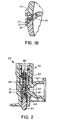
- the lower valve stem housing 60 is shown in more detail. It is provided with a metering orifice 63 extending into the pressure vessel 11 and a compression chamber 64 which feeds gas emitted from the carbon dioxide cartridge to the metering orifice 63 by the action of tapered pin 80 moving out of contact with its seat by valve stem 90.
- Metering orifice 63 is intended to allow only such quantity of carbon dioxide to pass as can easily be handled by the pressure safety relief valve 40 on the top cap assembly 33.
- the pressure used within the pressure vessel 11 has been satisfactory when it is of a value of 68.9 to 82.8 x 10 3 Pa (0.703-0.8436 kg/sq.cm.) (10-12 p.s.i.).
- a float 70 is diagrammatically illustrated as floating on or near the surface of the liquid held in the pressure vessel 11.
- the flcat 70 is made from polypropylene material and has a specific gravity of approximately .996 or slightly less than one so that it floats slightly below the surface of the liquid.
- the tube 72 already referred to above, extends from the float 70 to the spigot 23 where it is inserted within the spigot retaining nut 31.
- the float 70 has three ribs 73 ( Figure 3B) located equidistantly around and within the first diameter 74 of the float 70.
- the top cap 34 will be removed and a predetermined amount of known malt extract of approximately .95 litre (1 quart) is poured into the pressure vessel 11. Thereafter, a predetermined amount of water is added to the malt extract until the desired height of mixture is observed in the upper half 13 just below the co 2 dispenser 60 in the pressure vessel 11. A cold fermenting yeast is then added to the mixture and the mixture is left to allow the fermentation process to begin.
- the carbon dioxide emitted from the mixture during the fermentation process will create a pressure within the vessel 11. It is intended for this pressure not to exceed 82.8 x 10 3 Pa (0.8436 kg/sq.cm.) (12 p.s.i) since the vessel 11 has been designed with this pressure in mind for safety reasons. If the pressure exceeds 82.8 x 10 3 Pa (0.8436 kg/sq.cm. ) (12 p.s.i.), the pressure release valve 40 is adapted to open under the restraining influence of spring 42 and allow the excess pressure to bleed to atmosphere.
- the beer is ready for consumption and, to that end, the operator will insert a carbon dioxide cartridge into the cartridge housing 54 and screw the cartridge housing 54 down onto the lower valve stem housing 60 until the membrane in the cartridge is pierced by pin 82. This will allow carbon dioxide to be emitted from the cartridge and through the orifice 83 and into chamber 84. The operator will subsequently press the valve stem 90 upwardly as viewed in Figure 2 until the piston 91 is removed from the O-ring 92 which surrounds the piston 91 and seals the compression chamber 64 from chamber 84.
- Carbon dioxide will flow from the chamber 84 to chamber 64 and, thence, through orifice 63 and into the pressure vessel 11 at a rate such that no pressure spikes will occur in the pressure vessel and such that the pressure safety relief valve 40 is adequate to handle the release of any pressure over approximately 68.9 to 82.8 x 10 3 Pa (0.703-0.8436 kg/sq.cm.) (10-12 p.s.i.).
- the beer in the pressure vessel 11 due to the pressure to which it is subject, will flow upwardly within the recess extending from the entrance port 75 of the float 70 and into the open end of tube 72 where it will flow to the spigot 23.
- the use of the tube 72 having a reduced diameter allows the pressure of the beer to be reduced as it flows through the tube the tube 72 to the spigot 23.
- the pressure within the pressure vessel 11 is approximately 68.9 to 82.8 x 10 3 Pa (0.703-0.8436 kg/sq.cm.) (10-12 p.s.i)
- the pressure of the beer at the spigot 23 will preferably be approximately 13.8 x 10 3 Pa (0.1406 kg/sq.cm. ) (2 p.s.i.).
- the handle of the spigot 23 will subsequently be operated to allow the beer to exit the vessel 11 to the user under the influence of the pressure in the pressure vessel 11 caused by the carbon dioxide.
- the entire apparatus is easily disassembled.
- the bottom cap 51 is removed from the lower case half 14 and the top cap assembly 33 is removed from the upper case half 15.
- the base 12 is removed from the lower case half 14.
- the plastic slide bars 52 are slidably removed from the rails 15,16 and the mail seal 20 is removed from the recess 22 in the lower case half 14.
- the spigot 23, the carbon dioxide dispenser 53 and float 70 are likewise removed and easily disassembled.
- the beer making apparatus 10 can then be easily cleaned and reassembled for its next use.
- the pressure vessel 11 is made from PET, although other materials could, of course, be used.
- carbon dioxide has been found to be suitable for use in dispensing the beer, an inert gas such as nitrogen could also be used.
- an aerosol container appropriately designed could also be used.
- a beer making apparatus generally indicated at 89.
- the apparatus 89 is basically similar to the apparatus 10, but it has a modified pressure relief valve assembly. Parts of the apparatus 10 are indicted by like reference numerals.
- the pressure relief valve assembly of the apparatus 89 is generally shown at 90.
- the assembly 90 is shown located on the threaded connection 44 of the upper case half 13. It replaces the top cap assembly 33 shown in Figure 1A.
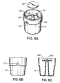
- the assembly 90 comprises a circular base member 92 having a cylindrical skirt 94 depending therefrom and having a flange 96 extending around the upper part of the skirt 94.
- the member 92 further has a central screw threaded part 98 for receiving a screw threaded cap 100 thereon, the cap 10 is provided with a plurality of circumferentially spaced slots 102 to act as air vents.
- the screw threaded part 98 has a central bore 104 in which is received a bung 106 having a central bore 108.
- the bung 106 is, in addition, provided with a pair of diametrically opposite grooves 110 extending along the lower part thereof ( Figure 5A).
- the bung 106 is of a resilient material and it has an outer diameter slightly larger than the inner diameter of the bore 104 so that it forms a press fit in the bore 104.
- a pressure safety relief valve 112 is located in the cap 100 and it rests on the bung 106 which acts as a valve seat.
- a spring 114 adapted to provide the necessary predetermined tension to the pressure relief valve 112, is provided and the cap 100 retains the spring 114 on the valve 112.
- the valve has a stem 116 which projects through an opening in the top of the cap 100 and serves as a guide for the valve 112.
- valve 112 and the spring 114 are on the outside of the pressure vessel 11 and thus less likely to be exposed to the contents of the vessel 11.
- the press fit of the bung 106 in the bore 104 is such that the bung 106 will be forced upwards should the pressure exceed a predetermined value which is higher than the normal operating pressure of the pressure relief valve 112.
- the bung 106 will be forced upwards to expose the grooves 110 to the outside of the vessel 11 or even, in extreme cases, to force the bung 106 out of the bore 104, thereby to relieve the pressure inside the vessel 11 should the pressure relief valve 112 fail, for example, due to clogging of the bore 108.
- the upper and lower case halves 13,14 of the vessel 11 are designed so that they will separate at the four corners of the halves 13,14 to release pressure in the unlikely event of the pressure relief valve assembly 90 failing altogether.
- the mutually facing surfaces between which the seal 20 is sandwiched will tend to separate to allow pressure to escape at the corners. This is facilitated by the seal 20 having upper lips 121, as shown in Figure 4B, which can be forced open as the surfaces at the corners are separated during pressure increase to open up the seal 20.
- the vessel 11 has been designed for this to occur at a pressure of about 206.8 to 241.3 x 10 3 Pa (2.109-2.4605 kg/sq.cm.)(30-35 p.s.i.).
- the relief valve assembly 90 is held in place on the threaded connection 44 by a screw threaded cap 115 having a central opening 117 therein.
- a rubber seal 119 is located between the flange 96 and the top of the threaded connection 44. The seal 119 is clamped between the flange 96 and the top of threaded connection 44, forming a passive seal.
- the pressure used in the pressure vessel has been referred to as being of a value of 68.9 to 82.8 x 10. 3 Pa (0.703-0.8436 kg/sq.cm.)(10-12 p.s.i.).
- an even higher pressure of a value of 89.6 to 103.4 x 10 3 Pa (0.9139-1.0545 kg/sq.cm.)(13-15 p.s.i.) has also been found to be satisfactory and is preferred when used with the apparatus 89.
- the pressure relief valve assembly 90 is adapted to relieve the pressure when the pressure exceeds a value of about 117.2 x 10 3 Pa (1.1951 kg/sq/cm.)(17 p.s.i.) rather than 82.8 x 10 3 Pa (0.8436 kg/sq.cm.)(12 p.s.i.) referred to earlier in connection with the pressure relief valve 40.
- a cup 116 having a plurality of circumferentially spaced openings 118 is located under the valve assembly 90. It has an inner diameter so that it will frictionally engage around the skirt 94.
- the openings 118 serve to break up the foam passing therethrough, due to surface tension. Sediment carried by the broken up foam will settle in the bottom of the cup 116 and is periodically cleaned out.
- the cup 116 may also be used in conjunction with the top cap assembly 33 shown in Figure 1A.
- the cup 116 has a central pin 120 on which is received a disk 122.
- the disc 122 is of a porous material which is impregnated with a chemical defoamer, as a precaution, to break up any foam not broken up during entry through the openings 118. It has been found that a fatty acid, preferably oleic acid, serves as an effective defoamer in this application, but other suitable fatty acids or mixtures thereof can also be used.
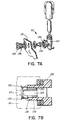
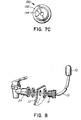
- the carbon dioxide pressure valve 53 is shown with a backflow preventing plug 130 according to a further aspect of the invention.
- the plug 130 has a flange 132 at one end and a groove 134 extending along part of its length, as shown in Figure 7B.
- a retaining cap 135 is provided which has an external screw thread, as shown at 136. It fits on the inside of the upper case half 13 and screws into a mating thread 138 on the inside of the housing 60 to mount the valve 53 on the upper case half 13.
- the plug 130 is located in the bore of the cap 135 so that one end of the groove 134 projects from the cap 135 to allow the passage of CO 2 gas from the valve 53 into the vessel 11 ( Figure 7B).
- the outer diameter of the flange 132 is greater than the inside diameter of an inside tapered surface (shown in broken line) of the housing 60.
- the flange 132 will be folded backwards (not shown in the drawing) as it presses against the tapered inside surface of the housing 60, to effectively form a one-way valve. It will allow the passage of CO 2 gas from the carbon dioxide cartridge but not the passage of gas or fluid from the inside of the vessel 11. This protects the valve 53 from backflow from the vessel 11 which could interfere with its proper functioning.
- the pressure vessel 11 serves three purposes. Firstly, it serves as a fermentation vessel where the fermentation process takes place. Secondly, it serves as a conditioning vessel where conditioning of the beverage by the addition of CO 2 gas and/or the lowering of the temperature thereof. Thirdly, the vessel 11 has been designed to serve as a dispenser from which the finished product can be dispensed directly into a drinking vessel for consumption. This is facilitated by the use of the float 70 by means of which the beverage is drawn off from the surface of the liquid and not from the bottom. The vessel 11 is further of a size so as to conveniently fit into a household refrigerator for the conditioning of the beverage and to chill the beverage for consumption. During the cooling of the beverage, when conditioning takes place, it accepts CO 2 which results in the beer attaining a desired flavour and encourage removal of turbidity.
- the final produce therefore does not need to be transferred to another vessel for conditioning or for storage prior to consumption.
- cup 116 prevents the beverage in the vessel 11 from coming into contact with the chemical defoaming agent, as happens with conventional systems. Thus, the beverage being ccnsumed is uncontaminated by the defoaming agent.
- the apparatus can be used for making other fermented beverages, alcoholic or non-alcoholic. It is also contemplated that the apparatus can be used for the production of wine or products using other fruit juice concentrates.
Landscapes
- Chemical & Material Sciences (AREA)
- Organic Chemistry (AREA)
- Engineering & Computer Science (AREA)
- General Engineering & Computer Science (AREA)
- Genetics & Genomics (AREA)
- Life Sciences & Earth Sciences (AREA)
- Biochemistry (AREA)
- Bioinformatics & Cheminformatics (AREA)
- Food Science & Technology (AREA)
- General Health & Medical Sciences (AREA)
- Health & Medical Sciences (AREA)
- Zoology (AREA)
- Wood Science & Technology (AREA)
- Chemical Kinetics & Catalysis (AREA)
- Non-Alcoholic Beverages (AREA)
- Devices For Dispensing Beverages (AREA)
- Vacuum Packaging (AREA)
- General Preparation And Processing Of Foods (AREA)
- Distillation Of Fermentation Liquor, Processing Of Alcohols, Vinegar And Beer (AREA)
Claims (41)
- Eine Einrichtung zum Vergären eines vergärbaren Flüssigkeitsgemisches, welche Einrichtung enthält:(a) Einen Druckbehälter (11), der eine geschlossene Gärkammer zur Aufnahme eines Bades begrenzt, das eine Menge des vergärbaren Flüssigkeitsgemisches enthält, die ausreichend ist, eine Oberfläche auf dem Bad innerhalb der Kammer zu bilden,(b) wobei der Druckbehälter voneinander lösbare Abschnitte (13, 14) und Verschlußelemente (52) umfaßt, um die beiden voneinander trennbaren Abschnitte zur Bildung dieser geschlossenen Gärkammer aneinander zu befestigen, und um eine Hauptdichtung (20) zwischen den beiden voneinander trennbaren Abschnitten zusammenzudrücken, um den Druck innerhalb der Kammer während der Benutzung der Einrichtung aufrechtzuerhalten, um einen Vorrat an gegorenem Getränk zu bilden,(c) wobei dieser Druckbehälter einen Einlaß (33) zum Einleiten des vergärbaren Flüssigkeitsgemisches in die Kammer und zum Zugeben einer Gärhefe in das Bad dieses vergärbaren Flüssigkeitsgemisches aufweist,(d) Druckentlastungselemente (40, 42, 43), um den Druck innerhalb der Gärkammer auf einem Niveau aufrechtzuerhalten, das ausreicht, um während des Gärprozesses die Sicherheitsbedingungen zu gewährleisten,(e) einen Druckgeber (53), um unter Druck stehendes Inert-Gas in den Druckbehälter einzuleiten, und(f) eine Eintrittsöffnung (75), die schwimmend gelagert ist, um gegorenes Getränk von unten und benachbart zur Badoberfläche aufzunehmen, um das gegorene Getränk durch ein Rohr (72) einem Zapfhahn (23) zuzuführen, um das Getränk aus dem Druckbehälter auszuschenken, während der Behälter weiterhin unter Druck steht.
- Eine Einrichtung gemäß Anspruch 1, bei der der Einlaß eine Deckelkappeneinheit ist, die an der Oberseite des Druckbehälters (11) oberhalb der Oberfläche des vergärbaren Flüssigkeitsbades angeordnet ist.
- Eine Einrichtung gemäß Anspruch 1 oder 2, bei der die Druckentlastungselemente (40, 42, 43) auf dem Druckbehälter (11) angeordnet sind, um Gas aus der unter Druck stehenden Atmosphäre freizusetzen.
- Eine Einrichtung gemäß Anspruch 2 oder 3, bei der der Einlaß (33) ein Anschlußstück (44) an dem Druckbehälter über der Badoberfläche enthält und die Deckelkappeneinheit eine Kappe (34) aufweist, um das Ingredienzieneinlaß-Anschlußstück (44) zu verschließen, nachdem die Gäringredienzien in die Kammer eingefüllt worden sind, und wobei diese Kappeneinheit diese Druckentlastungselemente (40, 42, 43) umfaßt, um Gas aus der unter Druck stehenden Atmosphäre durch den Einlaß (33) freizugeben.
- Eine Einrichtung gemäß einem der vorhergehenden Ansprüche, bei der die Eintrittsöffnung (75) zur Aufnahme von gegorenem Getränk aus dem Bad an einer Stelle benachbart zur Badoberfläche von einem Schwimmkörper (70) getragen ist, um das gegorene Getränk von der Eintrittsöffnung (75) durch ein Abgaberohr (72) zu einem Zapfhahn (23) zu leiten, der an den Druckbehälter (11) unterhalb der Badoberfläche angeschlossen und an der Außenseite des Druckbehälters angeordnet ist, um gegorenes Getränk aus dem Bad auszuschenken.
- Eine Einrichtung gemäß Anspruch 5, bei der das Rohr (72) einen Innendurchmesser hat, der wirksam ist, um innerhalb des Rohres einen Saugdruck mit einem Niveau unterhalb dem Gasdruck innerhalb des Druckbehälters (11) zu erzeugen.
- Eine Einrichtung gemäß Anspruch 5 oder 6, bei der das Rohr (72) in der Lage ist, einen Saugdruck von etwa (13.8 x 10³Pa (0.1406 kg/cm2) (2p.s.i.) an dem Zapfhahn zu erzeugen.
- Eine Einrichtung gemäß einem der vorhergehenden Ansprüche, bei der der Druckbehälter (11) ein transparentes Material enthält, um den Gärprozeß in dem Bad innerhalb der geschlossenen Kammer überwachen zu können.
- Eine Einrichtung gemäß Anspruch 8, bei der die voneinander trennbaren Abschnitte (13, 14) aus einem Kunststoff bestehen, der eine geringe Sauerstoffpermeabilitätsrate hat, so daß das Getränk nur einer geringen Geschmacksverschlechterung ausgesetzt ist.
- Eine Einrichtung gemäß Anspruch 5, bei der der Kunststoff transparent ist.
- Eine Einrichtung gemäß einem der vorhergehenden Ansprüche, bei der die Hauptdichtung einen konstanten Querschnitt und eine Ringform hat.
- Eine Einrichtung gemäß einem der vorhergehenden Ansprüche, bei der die voneinander trennbaren Abschnitte (13, 14) identische Gehäusehälften sind, welche Schienen (15, 16) haben, die sich vollständig um die Peripherie derselben erstrecken.
- Eine Einrichtung gemäß Anspruch 12, bei der die Verschlußelemente (52) über die Schienen (15, 16) geklemmt sind.
- Eine Einrichtung gemäß Anspruch 12 oder 13, bei der jedes Verschlußelement (42) eine Kunststoff-Schiebeklammer ist, die in fester Passung über die Schienen schiebbar ist, derart, daß die Hauptdichtung (12) zwischen den oberen und unteren Gehäusehälften (13, 14) zusammengedrückt wird, und derart, daß die oberen und unteren Gehäusehälften (13, 14) lecksicher dicht zusammengehalten werden.
- Eine Einrichtung gemäß einem der vorhergehenden Ansprüche, bei der die Hauptdichtung (20) divergierende Vorsprünge aufweist, die sich nach innen in die Kammer erstrecken.
- Eine Einrichtung gemäß einem der vorhergehenden Ansprüche, bei der der Druckgeber (53) so angeordnet ist, daß unter Druck stehendes Inert-Gas durch eine in den Druckbehälter (11) oberhalb der Badoberfläche befindliche Öffnung (61) zuführbar ist.
- Eine Einrichtung gemäß Anspruch 16, bei der der Druckgeber (53) eine Dosieröffnung (63), einen Stift (80) und einen Ventilschaft (90) aufweist, um Inert-Gas in die unter Druck stehende Behälterkammer mit einer Geschwindigkeit einströmen zu lassen, die wirksam ist, um in dem Druckbehälter (11) keine Druckspitzen zu erzeugen.
- Eine Einrichtung gemäß Anspruch 16 oder 17, bei der der Druckgeber (53) ein Patronengehäuse (54) zur Aufnahme einer Patrone, einen Patronendurchstoßstift (82), um Zugriff zu dem Druckgas in der Patrone zu erhalten, eine Dosieröffnung (63) und einen zugespitzten Stift (80) aufweist, um das Inert-Gas mit einer gesteuerten Geschwindigkeit durch die Öffnung (61) in den Druckbehälter (11) einströmen zu lassen.
- Eine Einrichtung gemäß einem der Ansprüche 1 bis 15, bei der der Druckgeber (53) ein Patronengehäuse (54), das in der Lage ist, eine unter Druck stehendes Inert-Gas enthaltende Patrone aufzunehmen, eine Kappe, die in der Lage ist, dieses Gehäuse an diesem Druckbehälter (11) zu befestigen, eine erste Druckkammer (84) in dem Gehäuse, die in der Lage ist Druck mit einem ersten Druckniveau zu enthalten und eine weitere, hinter dieser Kammer (34) befindliche Druckkammer (64), die in der Lage ist, Druck mit einem zweiten Druckniveau aufzunehmen, wobei dieses zweite Druckniveau niedriger liegt als dieses erste Druckniveau, und einen Kolben (91) aufweist, um eine Verbindung zwischen diesen Druckkammern herzustellen, wobei diese weitere Kammer (64) durch eine Bohrung an das Innere dieses Druckbehälters (11) angeschlossen ist.
- Eine Einrichtung gemäß Anspruch 19, bei der dieser Geber (53) ein Einwegeventil (130) aufweist, um eine Fluidströmung aus diesem Druckbehälter (11) in diese zweite Druckkammer (64) zu verhindern.
- Eine Einrichtung gemäß Anspruch 20, bei der dieses Patronengehäuse eine sich verjüngende Oberfläche aufweist, die sich in Richtung dieser zweiten Druckkammer (64) verjüngt, wobei dieses Einwegeventil (130) ein Stopfen mit einem Flansch (132) ist, der gegen diese sich verjüngende Oberfläche anliegt und in der Lage ist, sich zu verbiegen, um eine Fluidströmung aus dieser ersten Druckkammer (64) in diesen Behälter (11) zu ermöglichen, und abdichtend gegen diese sich verjüngende Oberfläche anzuliegen, um eine Fluidströmung in der entgegengesetzten Richtung zu verhindern.
- Eine Einrichtung gemäß Anspruch 19, 20 oder 21, bei der dieser Druckgeber eine Inertgas-Patrone umfaßt, die, um diese erste Druckkammer unter Druck zu setzen, geöffnet werden kann.
- Eine Einrichtung gemäß einem der vorhergehenden Ansprüche, bei der ein Antischaumaggregat (94, 116, 118, 122) zwischen diesen Druckentlastungsventilelemeten (40, 42, 43) und dem Innenraum des Behälters (11) angeordnet ist, die dem entgegenwirkt, daß während dieses Gärprozesses gebildeter Schaum in Kontakt mit den Druckentlastungsventilelementen kommt; wobei dieses Antischaumaggregat ein chemisches Antischaummittel umfaßt, das auf einem Festkörper abgelagert ist.
- Die Einrichtung gemäß Anspruch 23, bei der dieses Antischaummittel eine Fettsäure umfaßt.
- Die Einrichtung gemäß Anspruch 24, bei der die Fettsäure Ölsäure ist.
- Die Einrichtung gemäß Anspruch 24 oder 25, bei der der Festkörper ein poröses Material umfaßt.
- Die Einrichtung gemäß Anspruch 23, 24, 25 oder 26, bei der der Festkörper innerhalb des Gehäuses untergebracht ist.
- Apparatur, wie sie in einem der Ansprüche 1 bis 27 beansprucht ist, bei der das Inertgas Kohlendioxid oder Stickstoff ist.
- Eine Einrichtung gemäß einem der vorhergehenden Ansprüche, bei der die bauliche Konfiguration einen Sockel (12) umfaßt, um den Druckbehälter während seiner Benutzung stabil in einem üblichen Haushaltskühlschrank zu lagern.
- Eine Einrichtung gemäß einem der vorhergehenden Ansprüche, bei der der Druckbehälter eine bauliche Konfiguration hat, die es ermöglicht, daß er in einen üblichen Baushaltskühlschrank zum Kühlen des Flüssigkeitsgemischbades paßt.
- Ein Verfahren zum Vergären eines vergärbaren Flüssigkeitsgemisches, um Bier unter Druck in einer Einrichtung gemäß Anspruch 1 und unter Kühlbedingungen herzustellen, entsprechend der Kombination von Prozeßschritten enthaltend:(a) Herstellen eines vergärbaren flüssigen Biergemisches, um ein Bad und eine unter Druck-stehende Atmosphäre oberhalb der Badfläche in der geschlossenen Gärkammer während des Gärprozesses zur Verfügung zu haben,(b) Zugabe von Gärhefe zu dem Bad in einer Menge, die ausreicht, um einen Gärprozeß in dem vergärbaren Flüssigkeitsgemisch zu bewirken, wodurch der Druck innerhalb des Druckbehälters erhöht wird,(c) Steuerung des Drucks in der Druckatmosphäre innerhalb der geschlossenen Gärkammer auf ein Niveau, welches ausreicht, die Sicherheitsbedingungen während der Verwendung des Druckbehälters zu gewährleisten,(d) Abkühlen des innerhalb der unter Druck stehenden, geschlossenen Kammer enthaltenen Gemisches auf eine Temperatur, die in einem üblichen Haushaltskühlschrank herrscht, wobei diese Temperatur niedriger ist als die Umgebungstemperatur außerhalb des Kühlschranks,(e) Einleiten eines unter Druck stehenden Druckgases in den Druckbehälter, sobald das Bier für den Verbrauch fertig ist, um einen vorgegebenen Druck oberhalb des Bades innerhalb der Kammer aufrechtzuerhalten,(f) Entnahme von Bier aus dem der Badoberfläche benachbarten Bereich bei einem Schankdruck, der niedriger ist als der Druck der unter Druck stehenden Atmosphäre oberhalb der Badoberfläche.
- Ein Verfahren gemäß Anspruch 31, bei den der Druck der Atmosphäre oberhalb der Badoberfläcxbe in einem Bereich von etwa 68.9 bis 82.8 x 10³Pa (0.703-0.8436 kg/cm2) (10 bis 12 p.s.i.) gehalten wird.
- Ein Verfahren gemäß Anspruch 31, bei dem der Druck der Atmosphäre oberhalb der Badoberfläche nicht höher liegt als 82.8 x 10³Pa (0.8436 kg/cm2.) (12 p.s.i.).
- Ein Verfahren gemäß Anspruch 31, bei dem der Schankdruck im Bereich von 13.8 x 10³Pa (0.1406 kg/cm2.) (p.s.i.) liegt.
- Ein Verfahren gemäß einem der Ansprüche 31 bis 34, bei dem das Inertgas Stickstoff ist.
- Ein Verfahren gemäß einem der Ansprüche 31 bis 34, bei dem das Inertgas Kohlendioxid ist.
- Ein verfahren gemäß Anspruch 31, 35 oder 36, bei dem das Inertgas in den Druckbehälter mit einer Geschwindigkeit eingeleitet wird, die wirksam ist, um keine Druckspitzen innerhalb des Druckbehälters zu erzeugen.
- Ein Verfahren gemäß Anspruch 31, bei dem das Inertgas in den unter Druck stehenden Behälter an einer Stelle oberhalb der Badoberfläche eingeleitet wird.
- Ein Verfahren gemäß Anspruch 31, bei dem die Gärhefe eine Kaltgärhefe ist und das Bad nach der Zugabe der Kaltgärhefe auf üblicher Raumtemperatur für eine Zeit gehalten wird, die ausreicht, um den Abschluß der Initialphase der Gärung zu ermöglichen, wobei einschließend der Druckbehälter in einen üblichen Haushaltskühlschrank gestellt wird, bis der Gärprozeß abgeschlossen und das Bier für den Verbrauch fertig ist.
- Ein Verfahren nach Anspruch 39, bei dem die Zeit bei der Temperatur für die Initialphase der Vergärungen bei gewöhnlicher Raumtemperatur von 3 bis 4 Tagen liegt.
- Ein Verfahren nach Anspruch 39, bei dem die Zeit bis zur Beendigung des Gärprozesses innerhalb einer Siebentage-Periode liegt.
Applications Claiming Priority (3)
| Application Number | Priority Date | Filing Date | Title |
|---|---|---|---|
| US07/685,067 US5235901A (en) | 1989-11-27 | 1991-04-12 | Method and apparatus for making a fermented beverage |
| US685067 | 1991-04-12 | ||
| PCT/CA1992/000151 WO1992018606A1 (en) | 1991-04-12 | 1992-04-13 | Method and apparatus for making a fermented beverage |
Publications (2)
| Publication Number | Publication Date |
|---|---|
| EP0672108A1 EP0672108A1 (de) | 1995-09-20 |
| EP0672108B1 true EP0672108B1 (de) | 1998-08-26 |
Family
ID=24750649
Family Applications (1)
| Application Number | Title | Priority Date | Filing Date |
|---|---|---|---|
| EP92908733A Expired - Lifetime EP0672108B1 (de) | 1991-04-12 | 1992-04-13 | Verfahren und Vorrichtung zum Herstellen eines fermentierten Getränks. |
Country Status (8)
| Country | Link |
|---|---|
| US (1) | US5235901A (de) |
| EP (1) | EP0672108B1 (de) |
| JP (1) | JPH06506346A (de) |
| AT (1) | ATE170218T1 (de) |
| AU (2) | AU667302B2 (de) |
| CA (1) | CA2108024C (de) |
| DE (2) | DE69226791T4 (de) |
| WO (1) | WO1992018606A1 (de) |
Families Citing this family (18)
| Publication number | Priority date | Publication date | Assignee | Title |
|---|---|---|---|---|
| US5866107A (en) * | 1995-08-30 | 1999-02-02 | Cosmair, Inc. | Dust free bleach |
| US5823222A (en) * | 1996-10-31 | 1998-10-20 | Labatt Brewing Company Limited | Sanitary sampling device and method for using same |
| DE19740035C1 (de) * | 1997-09-11 | 1998-07-23 | Hrch Huppmann Gmbh | Gärverfahren unter Ausschluß von Luftsauerstoff |
| US20040129144A1 (en) * | 2003-01-06 | 2004-07-08 | Beadle Leigh Patric | Single stage beer brewing method and system |
| NO20063690L (no) * | 2006-08-16 | 2008-02-18 | House Brewery Norway As | Apparat og fremgangsmate for olbrygging |
| ES2661176T3 (es) * | 2007-08-01 | 2018-03-27 | Williamswarn Holdings Limited | Sistema de elaboración combinada |
| USD601382S1 (en) * | 2008-09-02 | 2009-10-06 | Ke-Anu Llc | Combined cooling serving container, liner and cover |
| NO331152B1 (no) * | 2009-10-19 | 2011-10-24 | Per Erik Hverven | Fremgangsmåte for fremstilling og tapping av øl, samt apparat for brygging og tapping av øl. |
| JP2013059300A (ja) * | 2011-09-14 | 2013-04-04 | Cbc Co Ltd | 発泡性アルコール飲料の製造容器及びそれを用いた製造方法並びに発泡性アルコール飲料の提供用車両及びその提供方法 |
| US20130264360A1 (en) * | 2012-04-05 | 2013-10-10 | Brewing Tools Llc | Reusable Vessel for Dispensing Beverages and Method of Storing and Dispensing Beverages |
| US20140057034A1 (en) * | 2012-08-22 | 2014-02-27 | Yung Hua Wang | Apparatus and method for making a beverage |
| US8561970B1 (en) | 2013-01-23 | 2013-10-22 | Brookstone Purchasing, Inc. | Aeration system |
| US20140326143A1 (en) * | 2013-05-06 | 2014-11-06 | 16 MILE BREWING COMPANY Inc. | Imbrue keg infusion apparatus and system |
| US20150203800A1 (en) * | 2014-01-22 | 2015-07-23 | Northern Brewer Llc | Modular keg for home brewing |
| USD879529S1 (en) | 2014-07-20 | 2020-03-31 | Cm Brewing Technologies | Container for brewing beer |
| US10004351B2 (en) * | 2016-01-22 | 2018-06-26 | Allan Erhart | Hot water dispenser adapter device |
| US9585510B1 (en) * | 2016-01-22 | 2017-03-07 | Allan Erhart | Hot water dispenser adapter device |
| USD829495S1 (en) * | 2016-07-04 | 2018-10-02 | Gea Brewery Systems Gmbh | Beer wort making apparatus |
Family Cites Families (47)
| Publication number | Priority date | Publication date | Assignee | Title |
|---|---|---|---|---|
| US275134A (en) * | 1883-04-03 | Apparatus for drawing liquids | ||
| CA464862A (en) * | 1950-05-02 | A.O. Smith Corporation | Foam skimmer | |
| US546115A (en) * | 1895-09-10 | Apparatus for drawing and serving steam-beer | ||
| US558131A (en) * | 1896-04-14 | Apparatus for racking beer | ||
| US512951A (en) * | 1894-01-16 | Device for drawing ale | ||
| GB190327551A (en) * | 1903-12-16 | 1904-12-16 | William Plomer Harris | Improvements in Combined Apparatus for Dry-hopping, Conditioning, Carbonating and Chilling Malt Liquors and for other like uses. |
| US808131A (en) * | 1904-10-24 | 1905-12-26 | Robert S Wiesenfeld | Beer-cooler. |
| FR409968A (fr) * | 1908-10-07 | 1910-05-07 | Emil Podszus | Appareil électrique à vapeurs, particulièrement applicable comme lampe |
| US936328A (en) * | 1909-02-19 | 1909-10-12 | Etienne Williams Kuhn | Process of manufacturing fermented beverages. |
| US1033136A (en) * | 1910-11-05 | 1912-07-23 | Henning Wennersten | Receptacle for fermenting liquids. |
| US1041298A (en) * | 1912-03-18 | 1912-10-15 | Karl Kiefer | Process of making alcohol. |
| US1302549A (en) * | 1915-08-02 | 1919-05-06 | Herman Heuser | Process for brewing beer. |
| US1389101A (en) * | 1918-08-05 | 1921-08-30 | Ohrvall Oscar | Foam or froth dissipator |
| GB217714A (en) * | 1923-05-02 | 1924-06-26 | Robert Oliver Mcgown | Improvements in or relating to draw off devices for liquids |
| US1831585A (en) * | 1930-04-04 | 1931-11-10 | Zerweck Herman | Minim alcohol beverage |
| US1917582A (en) * | 1933-03-27 | 1933-07-11 | Gordon Arthur | Beer separator and dispensing faucet |
| US2031397A (en) * | 1934-02-27 | 1936-02-18 | August L Voight | Beer cooler |
| US2136685A (en) * | 1937-06-04 | 1938-11-15 | Anheuser Busch | Method for manufacturing beer |
| US2239315A (en) * | 1937-10-15 | 1941-04-22 | Vigier William De | Extensible centering and like support |
| FR848091A (fr) * | 1938-12-28 | 1939-10-23 | Dispositif pour empêcher l'allumage et l'explosion des liquides volatils contenus dans des récipients | |
| US2593770A (en) * | 1946-07-10 | 1952-04-22 | Kollsman Paul | Device for carbonating and dispensing beverages |
| US2521397A (en) * | 1948-01-02 | 1950-09-05 | Muller Ferdinand | Fermenting and ripening of beer |
| FR1070239A (fr) * | 1953-01-31 | 1954-07-20 | Belcolor | Appareil pour la cuisson rapide des aliments sous pression |
| GB922200A (en) * | 1960-01-18 | 1963-03-27 | Frank Wyatt Lawson | Improvements relating to containers |
| US3374726A (en) * | 1966-06-07 | 1968-03-26 | Asahi Breweries Ltd | Beverage fermentation and storage tank of a large capacity |
| US3528817A (en) * | 1967-12-22 | 1970-09-15 | Harold F Barrett | Method and apparatus for making fermentable beverages |
| US3679600A (en) * | 1970-11-23 | 1972-07-25 | Eastman Kodak Co | Container with means for defoaming foaming liquids |
| US3760711A (en) * | 1971-12-23 | 1973-09-25 | Plastimade Inc | Apparatus in the form of a kit for home wine making |
| US3946780A (en) * | 1973-01-04 | 1976-03-30 | Sellers John C | Fermentation container |
| CH595868A5 (en) * | 1974-05-13 | 1978-02-28 | Process Engineering Co | Foam separator at outlet of fermentation vessel - has heater for reducing viscosity of viscous foam |
| JPS5266887A (en) * | 1975-11-29 | 1977-06-02 | Shin Etsu Chem Co Ltd | Defoaming agent composition |
| US4016904A (en) * | 1975-12-29 | 1977-04-12 | Central Safety Equipment Co. | Safety vent valve |
| US4222972A (en) * | 1979-01-29 | 1980-09-16 | Caldwell Michael C | Method and means for carbonating liquids in situ |
| US4343824A (en) * | 1979-01-29 | 1982-08-10 | Caldwell Michael C | Method for carbonating liquids in situ |
| AT362332B (de) * | 1979-04-09 | 1981-05-11 | Kuehtreiber Franz | Einrichtung zur herstellung von bier |
| US4218964A (en) * | 1979-05-21 | 1980-08-26 | Specialty Products International, Ltd. | Lid construction for fermentation container |
| US4267940A (en) * | 1979-06-26 | 1981-05-19 | Purex Corporation | Removable clamp structure for tank sections which at times block said removal |
| LU81885A1 (fr) * | 1979-11-14 | 1980-06-05 | Participation Et D Investiss C | Appareil collecteur de mout chaud et separateur du trub et et des houblons equises |
| US4373024A (en) * | 1980-12-02 | 1983-02-08 | Phillips Petroleum Company | Apparatus useful for foam breaking |
| US4399744A (en) * | 1981-04-06 | 1983-08-23 | Ralph Ogden | Beverage carbonator device |
| GB2112124B (en) * | 1981-12-18 | 1985-09-18 | Clearline Home And Leisure Pro | Gas cylinder fitting |
| US4423670A (en) * | 1982-06-29 | 1984-01-03 | Tenison Earnest M | Fermenting and carbonating apparatus |
| GB2123850B (en) * | 1982-07-09 | 1987-04-15 | Donald Paul Pilla | A fermentation apparatus |
| DE3438657A1 (de) * | 1984-10-22 | 1986-04-24 | EKATO Industrieanlagen Verwaltungsgesellschaft mbH u. Co, 7860 Schopfheim | Turbine zum zerstoeren von schaum |
| US4775482A (en) * | 1985-05-28 | 1988-10-04 | Mederi Medical Systems, Inc. | Method for removing fat and for purifying and defoaming liquids |
| SU1346187A1 (ru) * | 1986-03-19 | 1987-10-23 | Ленинградский технологический институт холодильной промышленности | Устройство дл разрушени пены |
| US4754698A (en) * | 1986-12-01 | 1988-07-05 | Naish Ralph P | Home brewing apparatus |
-
1991
- 1991-04-12 US US07/685,067 patent/US5235901A/en not_active Expired - Lifetime
-
1992
- 1992-04-13 DE DE69226791T patent/DE69226791T4/de not_active Expired - Lifetime
- 1992-04-13 DE DE69226791A patent/DE69226791D1/de not_active Expired - Fee Related
- 1992-04-13 CA CA002108024A patent/CA2108024C/en not_active Expired - Fee Related
- 1992-04-13 EP EP92908733A patent/EP0672108B1/de not_active Expired - Lifetime
- 1992-04-13 AU AU15756/92A patent/AU667302B2/en not_active Ceased
- 1992-04-13 AT AT92908733T patent/ATE170218T1/de not_active IP Right Cessation
- 1992-04-13 WO PCT/CA1992/000151 patent/WO1992018606A1/en not_active Ceased
- 1992-04-13 JP JP4507603A patent/JPH06506346A/ja active Pending
-
1996
- 1996-01-02 AU AU40772/96A patent/AU676650B2/en not_active Ceased
Also Published As
| Publication number | Publication date |
|---|---|
| JPH06506346A (ja) | 1994-07-21 |
| AU1575692A (en) | 1992-11-17 |
| DE69226791D1 (de) | 1998-10-01 |
| CA2108024C (en) | 2005-06-14 |
| DE69226791T4 (de) | 2000-06-29 |
| WO1992018606A1 (en) | 1992-10-29 |
| ATE170218T1 (de) | 1998-09-15 |
| AU667302B2 (en) | 1996-03-21 |
| CA2108024A1 (en) | 1992-10-13 |
| AU676650B2 (en) | 1997-03-13 |
| DE69226791T2 (de) | 1999-05-20 |
| US5235901A (en) | 1993-08-17 |
| EP0672108A1 (de) | 1995-09-20 |
| AU4077296A (en) | 1996-03-07 |
Similar Documents
| Publication | Publication Date | Title |
|---|---|---|
| US5365830A (en) | Assembly for the domestic making of a fermented beverage under chilled pressure conditions | |
| EP0672108B1 (de) | Verfahren und Vorrichtung zum Herstellen eines fermentierten Getränks. | |
| US10081530B2 (en) | Fluid pressurization and dispensing system | |
| US4475576A (en) | Wine preservation system | |
| US5364639A (en) | Beer making method | |
| US7722908B2 (en) | Method of maturing wine | |
| US4423670A (en) | Fermenting and carbonating apparatus | |
| US20120196016A1 (en) | Tank for the storage and/or maturation of an alcoholic beverage | |
| CA2708423A1 (en) | Device for dosed dispensing of a liquid from a composite container and method for filling such a container with liquid | |
| AU2010235968A1 (en) | Beverage packaging | |
| WO1999050383A2 (en) | Micro-brewing device | |
| UA77050C2 (en) | Method and device of industrial production of bubbly alcohol-containing beverages (variants) | |
| AU2010227113A1 (en) | A Tank System for the storage and/or maturation of a liquid beverage | |
| GB2217787A (en) | A liquid dispensing device | |
| AU2008101169B4 (en) | Maturation of Liquid Beverage | |
| AU2011100514B4 (en) | Beverage Packaging | |
| AU2008100043A4 (en) | Wine Storage | |
| CA1113413A (en) | Fermentation apparatus | |
| EP0241535A1 (de) | Verfahren und anordnung zum aufbewahren und verabreichen von getränken | |
| CA1339855C (en) | Beer making method and apparatus | |
| BG66030B1 (bg) | Опаковачно средство за течна мая | |
| EP4731741A1 (de) | Erfindung betreffend verfahren zum starten eines fermentationsverfahrens in einem geschlossenen behälter | |
| AU2010100553A4 (en) | A tank system for the storage and maturation of wine | |
| AU2004293488A1 (en) | Control of oxygenation |
Legal Events
| Date | Code | Title | Description |
|---|---|---|---|
| PUAI | Public reference made under article 153(3) epc to a published international application that has entered the european phase |
Free format text: ORIGINAL CODE: 0009012 |
|
| 17P | Request for examination filed |
Effective date: 19931102 |
|
| AK | Designated contracting states |
Kind code of ref document: A1 Designated state(s): AT DE FR GB IT NL SE |
|
| 17Q | First examination report despatched |
Effective date: 19960607 |
|
| GRAG | Despatch of communication of intention to grant |
Free format text: ORIGINAL CODE: EPIDOS AGRA |
|
| GRAG | Despatch of communication of intention to grant |
Free format text: ORIGINAL CODE: EPIDOS AGRA |
|
| GRAH | Despatch of communication of intention to grant a patent |
Free format text: ORIGINAL CODE: EPIDOS IGRA |
|
| GRAH | Despatch of communication of intention to grant a patent |
Free format text: ORIGINAL CODE: EPIDOS IGRA |
|
| GRAA | (expected) grant |
Free format text: ORIGINAL CODE: 0009210 |
|
| AK | Designated contracting states |
Kind code of ref document: B1 Designated state(s): AT DE FR GB IT NL SE |
|
| PG25 | Lapsed in a contracting state [announced via postgrant information from national office to epo] |
Ref country code: FR Free format text: LAPSE BECAUSE OF FAILURE TO SUBMIT A TRANSLATION OF THE DESCRIPTION OR TO PAY THE FEE WITHIN THE PRESCRIBED TIME-LIMIT Effective date: 19980826 Ref country code: AT Free format text: LAPSE BECAUSE OF FAILURE TO SUBMIT A TRANSLATION OF THE DESCRIPTION OR TO PAY THE FEE WITHIN THE PRESCRIBED TIME-LIMIT Effective date: 19980826 |
|
| REF | Corresponds to: |
Ref document number: 170218 Country of ref document: AT Date of ref document: 19980915 Kind code of ref document: T |
|
| REF | Corresponds to: |
Ref document number: 69226791 Country of ref document: DE Date of ref document: 19981001 |
|
| EN | Fr: translation not filed | ||
| PGFP | Annual fee paid to national office [announced via postgrant information from national office to epo] |
Ref country code: SE Payment date: 19990414 Year of fee payment: 8 |
|
| PGFP | Annual fee paid to national office [announced via postgrant information from national office to epo] |
Ref country code: NL Payment date: 19990429 Year of fee payment: 8 |
|
| PGFP | Annual fee paid to national office [announced via postgrant information from national office to epo] |
Ref country code: DE Payment date: 19990626 Year of fee payment: 8 |
|
| PLBE | No opposition filed within time limit |
Free format text: ORIGINAL CODE: 0009261 |
|
| STAA | Information on the status of an ep patent application or granted ep patent |
Free format text: STATUS: NO OPPOSITION FILED WITHIN TIME LIMIT |
|
| 26N | No opposition filed | ||
| PG25 | Lapsed in a contracting state [announced via postgrant information from national office to epo] |
Ref country code: SE Free format text: LAPSE BECAUSE OF NON-PAYMENT OF DUE FEES Effective date: 20000414 |
|
| PG25 | Lapsed in a contracting state [announced via postgrant information from national office to epo] |
Ref country code: NL Free format text: LAPSE BECAUSE OF NON-PAYMENT OF DUE FEES Effective date: 20001101 |
|
| EUG | Se: european patent has lapsed |
Ref document number: 92908733.6 |
|
| NLV4 | Nl: lapsed or anulled due to non-payment of the annual fee |
Effective date: 20001101 |
|
| PG25 | Lapsed in a contracting state [announced via postgrant information from national office to epo] |
Ref country code: DE Free format text: LAPSE BECAUSE OF NON-PAYMENT OF DUE FEES Effective date: 20010201 |
|
| REG | Reference to a national code |
Ref country code: GB Ref legal event code: IF02 |
|
| PG25 | Lapsed in a contracting state [announced via postgrant information from national office to epo] |
Ref country code: IT Free format text: LAPSE BECAUSE OF NON-PAYMENT OF DUE FEES;WARNING: LAPSES OF ITALIAN PATENTS WITH EFFECTIVE DATE BEFORE 2007 MAY HAVE OCCURRED AT ANY TIME BEFORE 2007. THE CORRECT EFFECTIVE DATE MAY BE DIFFERENT FROM THE ONE RECORDED. Effective date: 20050413 |
|
| PGFP | Annual fee paid to national office [announced via postgrant information from national office to epo] |
Ref country code: GB Payment date: 20090417 Year of fee payment: 18 |
|
| GBPC | Gb: european patent ceased through non-payment of renewal fee |
Effective date: 20100413 |
|
| PG25 | Lapsed in a contracting state [announced via postgrant information from national office to epo] |
Ref country code: GB Free format text: LAPSE BECAUSE OF NON-PAYMENT OF DUE FEES Effective date: 20100413 |