EP0672265B1 - Systeme optique a large bande spectrale et champ de vision ultralarge comportant un affichage sur une visiere montee dans un casque - Google Patents
Systeme optique a large bande spectrale et champ de vision ultralarge comportant un affichage sur une visiere montee dans un casque Download PDFInfo
- Publication number
- EP0672265B1 EP0672265B1 EP94929965A EP94929965A EP0672265B1 EP 0672265 B1 EP0672265 B1 EP 0672265B1 EP 94929965 A EP94929965 A EP 94929965A EP 94929965 A EP94929965 A EP 94929965A EP 0672265 B1 EP0672265 B1 EP 0672265B1
- Authority
- EP
- European Patent Office
- Prior art keywords
- relay group
- image
- optical
- display system
- lens
- Prior art date
- Legal status (The legal status is an assumption and is not a legal conclusion. Google has not performed a legal analysis and makes no representation as to the accuracy of the status listed.)
- Expired - Lifetime
Links
- 230000003287 optical effect Effects 0.000 title claims description 72
- 230000003595 spectral effect Effects 0.000 title 1
- 230000004075 alteration Effects 0.000 claims description 38
- 206010010071 Coma Diseases 0.000 claims description 17
- 238000005452 bending Methods 0.000 claims description 12
- 238000001429 visible spectrum Methods 0.000 claims description 4
- 201000009310 astigmatism Diseases 0.000 description 15
- 210000001747 pupil Anatomy 0.000 description 6
- 238000013461 design Methods 0.000 description 5
- 238000013459 approach Methods 0.000 description 3
- 210000003128 head Anatomy 0.000 description 3
- 238000009125 cardiac resynchronization therapy Methods 0.000 description 2
- 230000009467 reduction Effects 0.000 description 2
- 206010027646 Miosis Diseases 0.000 description 1
- 230000015556 catabolic process Effects 0.000 description 1
- 239000011248 coating agent Substances 0.000 description 1
- 238000000576 coating method Methods 0.000 description 1
- 238000004590 computer program Methods 0.000 description 1
- 239000000470 constituent Substances 0.000 description 1
- 239000005331 crown glasses (windows) Substances 0.000 description 1
- 238000006731 degradation reaction Methods 0.000 description 1
- 238000010586 diagram Methods 0.000 description 1
- 239000006185 dispersion Substances 0.000 description 1
- 230000000694 effects Effects 0.000 description 1
- 230000005669 field effect Effects 0.000 description 1
- 239000005308 flint glass Substances 0.000 description 1
- 238000011835 investigation Methods 0.000 description 1
- 238000012804 iterative process Methods 0.000 description 1
- 239000000463 material Substances 0.000 description 1
- 238000000034 method Methods 0.000 description 1
- 238000004806 packaging method and process Methods 0.000 description 1
- 230000008569 process Effects 0.000 description 1
- 238000011160 research Methods 0.000 description 1
Images


Classifications
-
- G—PHYSICS
- G02—OPTICS
- G02B—OPTICAL ELEMENTS, SYSTEMS OR APPARATUS
- G02B27/00—Optical systems or apparatus not provided for by any of the groups G02B1/00 - G02B26/00, G02B30/00
- G02B27/01—Head-up displays
- G02B27/017—Head mounted
- G02B27/0172—Head mounted characterised by optical features
-
- G—PHYSICS
- G02—OPTICS
- G02B—OPTICAL ELEMENTS, SYSTEMS OR APPARATUS
- G02B27/00—Optical systems or apparatus not provided for by any of the groups G02B1/00 - G02B26/00, G02B30/00
- G02B27/01—Head-up displays
- G02B27/0101—Head-up displays characterised by optical features
- G02B2027/011—Head-up displays characterised by optical features comprising device for correcting geometrical aberrations, distortion
-
- G—PHYSICS
- G02—OPTICS
- G02B—OPTICAL ELEMENTS, SYSTEMS OR APPARATUS
- G02B27/00—Optical systems or apparatus not provided for by any of the groups G02B1/00 - G02B26/00, G02B30/00
- G02B27/01—Head-up displays
- G02B27/0101—Head-up displays characterised by optical features
- G02B2027/0112—Head-up displays characterised by optical features comprising device for genereting colour display
- G02B2027/0116—Head-up displays characterised by optical features comprising device for genereting colour display comprising devices for correcting chromatic aberration
-
- G—PHYSICS
- G02—OPTICS
- G02B—OPTICAL ELEMENTS, SYSTEMS OR APPARATUS
- G02B27/00—Optical systems or apparatus not provided for by any of the groups G02B1/00 - G02B26/00, G02B30/00
- G02B27/01—Head-up displays
- G02B27/0101—Head-up displays characterised by optical features
- G02B2027/0123—Head-up displays characterised by optical features comprising devices increasing the field of view
-
- G—PHYSICS
- G02—OPTICS
- G02B—OPTICAL ELEMENTS, SYSTEMS OR APPARATUS
- G02B27/00—Optical systems or apparatus not provided for by any of the groups G02B1/00 - G02B26/00, G02B30/00
- G02B27/01—Head-up displays
- G02B27/0101—Head-up displays characterised by optical features
- G02B2027/0143—Head-up displays characterised by optical features the two eyes not being equipped with identical nor symmetrical optical devices
-
- G—PHYSICS
- G02—OPTICS
- G02B—OPTICAL ELEMENTS, SYSTEMS OR APPARATUS
- G02B27/00—Optical systems or apparatus not provided for by any of the groups G02B1/00 - G02B26/00, G02B30/00
- G02B27/01—Head-up displays
- G02B27/017—Head mounted
-
- G—PHYSICS
- G02—OPTICS
- G02B—OPTICAL ELEMENTS, SYSTEMS OR APPARATUS
- G02B5/00—Optical elements other than lenses
- G02B5/04—Prisms
Definitions
- This invention relates to optical display systems in which an image is reflected off a surface at a large bending angle, producing asymmetric aberrations in the reflected image, and more particularly to the use of such systems for helmet mounted visor displays that include optical systems to compensate the aberrations.
- Aircraft helmet visor display systems project images that provide necessary pilot information onto the helmet visor immediately in front of the pilot's eyes, allowing the pilot to see both the image reflected from the visor, and the outside scene, in a "heads up" mode.
- a typical helmet visor display system is described in U.S. Patent No. 3,940,204, issued February 24, 1976 to Withrington and assigned to Hughes Aircraft Company, the assignee of the present invention. Further such display systems are known from US-A-4854688 and EP-A-0007039.
- the information image is provided from a cathode ray tube (CRT) mounted on the side of the helmet. The image is directed generally forward, and then deflected by a prism assembly onto the curved visor.
- CTR cathode ray tube
- the image is directed onto the visor at a substantial "bending angle" to a perpendicular from the center of the visor; the bending angle is typically about 55-60°. This results in significant asymmetrical aberrations in the reflected image.
- the aberrations produced with this asymmetrical system are quite complicated, and consist mainly of binodal astigmatism and coma.
- a relay lens group has been introduced between the CRT and the visor, with the relay group tilted and decentered in an effort to produce equal and opposite aberrations and thus balance out (compensate) the aberrations that result from the asymmetries.
- the tilt angle of the CRT was also adjusted for this purpose.
- the inner surface of the visor also referred to as a "combiner", since it combines both the projected information from the CRT and the outside scene
- the use of the relay group allowed the CRT to be kept small, while the combiner relayed the pupil of the wearer's eye to a location inside the relay group, thus allowing for a small size relay group.
- the efforts to reduce aberrations have not been wholly successful, however, and a significant residual aberration remained.
- Astigmatism and coma are two significant aberrations which limit the image quality of many optical systems.
- a symmetric optical system such as a camera lens
- the astigmatism is quadradically proportional to the field of view
- coma is linearly proportional to the field of view. Therefore, at the center of the field, astigmatism and coma are zero.
- an asymmetric optical system such as a high bending angle helmet visor display (HVD)
- HVD helmet visor display
- Astigmatism and coma generated by the visor are much more complicated than that of a symmetric system.
- Astigmatism is generally characterized as having components that vary quadratically and linearly with the field of view, and also a constant component.
- Coma for the asymmetric optical system includes a linear coma component that varies linearly with the field of view, and constant coma component that is constant over the field of view.
- Another approach has been to reduce the effective bending angle, and thereby eliminate the generation of asymmetric aberrations in the first place. This has been implemented by positioning a beam splitter directly in front of the wearer's eye to redirect the beam from the CRT, and thereby achieve a smaller bending angle and a wider field of view.
- a major problem with this approach is that it positions a distracting element very close to the wearer's eye, typically less than one-half inch away, and also obstructs the use of eyeglasses.
- holographic combiners have narrow bandwidths, typically restricting the system to a single color. This was not a particular problem with prior CRTs, which also had narrow bandwidths. However, more recent CRTs have a wider bandwidth, but the bandwidth of the overall system is limited to that of its narrowest bandwidth element, i.e., the holographic combiner. If the bandwidth limitation of the prior systems is removed by replacing the holographic combiner with a more conventional visor, however, both additional asymmetric aberrations and chromatic aberrations would result.
- the present invention seeks to provide an improved optical display system for use with a helmet visor or similar large bending angle application that provides a wide field of view and broad bandwidth, and yet exhibits a low level of optical aberrations.
- the system can generate a binodal astigmatism and both linear and constant coma that match and compensate for the visor aberrations with a large bending angle.
- the provision of two separate relay groups significantly increases the degrees of freedom available for the compensation process, and allows for the compensation of all three binodal astigmatism components and both coma components.
- the front relay group has a net positive focusing that focuses an image of the helmet wearer's eye pupil to a location near the front end of the rear relay group; this allows for a reduction in size of the rear relay group.
- the rear group also has a net positive optical power and collimates an image from the image generator to near collimation, thereby providing an apparent far field image to the wearer.
- the rear group functions as a biocular eyepiece with a large numerical aperture.
- a non-holographic reflecting surface is used for the visor, expanding its bandwidth to encompass substantially the full visible spectrum.
- lens doublets are used in both the front and rear relay groups, with both groups producing a net positive focusing.
- the rear group preferably includes a positive focusing lens between two sets of lens doublets.
- the front lens of the rear group also preferably has a positive optical power to further reduce the size of the relay and enlarge the pupil image size.
- An optical wedge is positioned between the image generator and the rear relay group to compensate for residual constant coma, with the misalignment between the front and rear relay groups selected to also compensate for chromatic aberrations introduced by the wedge.
- the invention will be described herein in terms of a heads up helmet display for pilot use. However, it should be recognized that the invention has numerous other applications in which an image is to be presented at a significant bending angle to a display surface located immediately in front of a viewer. Such applications include, for example, "virtual reality” devices, and instruments used to assist with the design or analysis of complicated structures such as DNA investigation or architectural designs.
- FIGs. 1 and 2 illustrate the application of the invention to a pilot helmet 2 that includes a visor 4.
- the inner visor surface facing the wearer serves as an optical combiner.
- Information images are generated by a CRT 6 that is mounted along the side of the helmet.
- the image at the CRT screen 8 is preferably redirected by a prism assembly 10 so that it points towards the visor, generally in front of the viewer's eyes.
- the wearer thus has a visible information display on the visor, as well as a clear view of the outside scene as indicated by arrow 12.
- the use of a prism assembly allows for better packaging of the optical components on the helmet.
- a pair of optical lens relay groups consisting of a forward relay group 14 and a rear relay group 16, are mounted to the helmet in the optical path 18 between the CRT screen 8 and the visor.
- the rear relay group 16 is generally located between the CRT 6 and the prism assembly 10, although for some applications it may be placed immediately to the rear of the front relay group 14, with the prism assembly 10 located between it and the CRT.
- the optical components are shown in block diagram format in FIGs. 1 and 2, and additional elements of the optical system are not depicted in these figures. A more complete description of the optical system is provided below in connection with FIGs. 3 and 4.
- the inner surface of visor 4 is a conventional reflective combiner, with a pertzval curvature that balances that of the relay groups.
- a see-through capability is provided for the combiner by applying a beam splitter type coating to it.
- This use of a non-holographic combiner which has a broad bandwidth encompassing substantially the full visible spectrum, allows for the use of a CRT 6 with a similarly broadband output. Chromatic aberrations that result from this broadband operation are compensated by the design of the relay groups 14, 16, as described below.
- the principal ray 18 of the center field of view from the CRT 6 to the visor 4 is defined herein as the optical axis. It has an angle of incidence ⁇ to the visor that is considerably offset from a perpendicular drawn to the visor at that point; the angular difference between the visor perpendicular and the axis 18 is referred to as the system's bending angle. It can be seen that the bending angle varies at different locations on the visor, but in generally it will typically be about 55°-60°.
- the asymmetric orientation of the visor with respect to the incident beam from CRT 6 results in the complex asymmetrical aberrations mentioned previously.
- the forward and rear relay groups 14, 16 can be oriented independent of each other to provide a significant increase in the degrees of freedom available to compensate for these aberrations.
- Either or both of the relay groups can be decentered with respect to each other and to the optical axis 18, i.e., shifted somewhat laterally so that the center of the relay group is no long centered on the axis 18.
- each relay group can be angularly tilted so that its internal axis is non-parallel to the system axis 18. Since each relay group can be positioned independent of the other, they can be misaligned with respect to each other by mutual decentering and angular tilting.
- the visor aberrations will generally have a plane of symmetry that includes the optical axis 18. At any pair of corresponding points above and below the plane, the incident light from the CRT will have traversed an equal distance, and will have the same angle of incidence to the visor. In FIG. 2 the plane of symmetry extends into the page. Since the optical aberrations will generally be symmetrical on opposite sides of this plane, the relay groups 14, 16 need only tilt and decenter in a plane that is generally parallel to the symmetry plane.
- the visor 4 and the other elements of the optical system are oriented so that the image from CRT 6 is directed onto the helmet wearer's eye 22.
- FIG. 3 has a similar orientation to FIG. 1, except the optical elements of FIG. 3 are shown as they would be mounted on the left side of a helmet, rather than the right side as in FIG. 1.
- the optical system could alternately be located on top of the helmet, in which case the decentering and tilt plane would rotate 90° from the corresponding plane for FIGs. 1 and 3, or at some other convenient location.
- the front relay group 14 consists of matched positive and negative lenses 24 and 26, which together comprise a lens doublet that compensates for chromatic aberrations, another positive lens 28, and a thick negative lens 30 between lens 28 and the rear relay group 16.
- the lens 30 has a slightly curved rear surface, and can also function as the prism assembly 10 of FIGs. 1 and 2 by implementing it with an optical turning angle.
- Lenses 28 and 30 comprise another lens doublet, with a net positive optical power. The operation of a lens doublet in compensating for chromatic aberrations is described in Smith, Modern Optical Engineering , McGraw Hill Book Company, 1966, pages 334-337.
- the positive optical power of the front relay group 14 relays an image of the helmet wearer's pupil to a location near the front lens 32 of the rear relay groups; this allows the rear relay group 16 to be constructed with a substantially smaller cross-sectional area than the front group.
- the front relay group 14 together with the visor/ combiner 4 function as an afocal telescope, with a collimated input beam resulting in a collimated output beam. It forms an intermediate image of the CRT display at an intermediate image plane 31.
- the rear relay group 16 preferably includes a front lens doublet consisting of positive lens 32 and negative lens 34, a rear lens doublet consisting of position lens 36 and negative lens 38, and a positive focusing lens 40 between the front and rear lens doublets.
- the front doublet has an air space between its two constituent lenses 32, 34; such an arrangement is known to reduce higher order aberrations.
- the middle positive lens 40 provides the rear relay group with a net positive focusing; a positive focusing for each relay group is necessary to produce a real image. While positive lenses 36 and 40 could be combined into a single lens having a greater surface curvature, this would aggravate the aberrations.
- the positive lenses in both relay groups are preferably formed from crown glass, which has a relatively low dispersion and a low refractive index differential for different wavelengths.
- the negative lenses are preferably formed from flint glass, which is more dispersive and has a larger refractive index differential for different wavelengths.
- the front relay group 14 is illustrated as having its optical center at point 42, and its optical axis 44 (show in dashed lines) extending through the center.
- the front relay group 14 is decentered to the right of the system's optical axis 18 (with the respect to a direction of travel from the relay group towards the visor 4). It is also angularly tilted, with its optical axis 44 intersecting the system axis 18 between the front relay group and the visor.
- the rear relay group 16 has its optical center at 46, and is also illustrated as being decentered to the right of the system axis 18, but by a different amount. In this example the rear relay group 16 is angularly tilted in the opposite sense to the front relay group, with its optical axis 48 intersecting the system axis 18 to the rear of the relay group 16.
- the particular decentering and tilting for each of the relay groups in a given system is preferably determined with the assistance of a computer program.
- Software packages with this capability are currently available, such as the CODEV® program by Optical Research Associates, Inc. of Pasadena, California.
- the system designer characterizes the optical system under consideration by inputting the radius of curvature and thickness of all lenses, the spacing between and positions of the lenses, the lens materials, the degrees of freedom for the decentering and tilt adjustments, and the characteristics of the visor surface.
- the program employs an iterative process that adjusts the decentering of the relay groups and their tilt angles slightly, observes how these adjustments impact the image quality, and continues with additional adjustment iterations to optimize the image quality and minimize aberrations.
- the front relay group 14 is designed to focus an image from the viewer's eye pupil 22, reflected off the inner surface of visor 4, to a location just forward of the rear relay group 16. This allows the cross-sectional area of the rear relay group to be considerably less than that of the forward group, without any loss of light.
- the first lens 32 of the rear relay group preferably has a positive optical power, which further reduces the size required for the relay group and enlarges the pupil image.
- the rear relay group in effect constitutes a biocular eyepiece with a large numerical aperture. It has a net positive optical power that focuses an image from the image generating surface 23 to near collimation, as can be seen from the optical ray traces 50a, 50b from the center of the image generator. This gives a desirable far field effect to the image seen on the visor by the wearer of the helmet.
- An optical wedge 52 is positioned between the image generating surface 23 and the rear relay group 16 to remove any residual coma that may be left from the remainder of the optical system.
- the characteristics of the wedge can also be added as an input to the software program used for the particular system design, with the program determining an optimum wedge tilt angle.
- the presence of the wedge may introduce a degree of chromatic aberration, but this can be compensated by adjusting the decentering of the front and/ or rear relay groups.
- the majority of all three binodal astigmatism components (quadratic, linear and constant), as well as both linear and constant coma, can be effectively compensated, while at the same time significantly increasing the field of view. Fields of view on the order of 60° horizontal ⁇ 80° vertical are achievable.
- the operating bandwidth can be extended to cover substantially the full visible spectrum, without a corresponding degradation in the image quality.
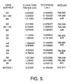
- the lens prescription for a particular system that uses the invention is given in FIG. 5.
- the system employs the lens arrangement shown in FIGs. 3 and 4.
- the radius of curvature for each lens surface is given in cm, with a positive number indicating a concave curvature as seen from the right hand side of the figure, and a negative number indication a convex curvature.
- the thickness, also given in cm, is the thickness from the center of the given lens surface to the center of the next surface to the left.
- the index of refraction and Abbe number for the medium immediately to the left of the lens surface is defined in the conventional six digit notation, with the index of refraction preceding the Abbe number.
- indices of refraction are in the form 1.xyz; the unit value 1 is omitted in FIG. 5 and only the three decimal figures are given.
- the first entry (796) corresponds to a refractive index of 1.796.
- All Abbe numbers are in the form of a two digit whole number followed by a single digit decimal (xy.z); the first entry 506 corresponds to an Abbe number 50.6.
- the front surface of a lens (as seen from the right hand side of the figure) is indicated by the letter f, and the rear surface by the letter r.
- the visor had a radius of curvature of -12.3444 cm and was spaced 17.1493 cm from lens 24; the image plane 23 had a radius of curvature of 19.3480 cm and was spaced 0.5334 cm behind the wedge 52.
- the front relay group 14 was not decentered in this particular example, but was tilted 2.665781°.
- the rear relay group was decentered 0.07353 cm and tilted -6.592328°.
- the wedge was tilted 9.200121° and the image plane -20.019865°.
Landscapes
- Physics & Mathematics (AREA)
- General Physics & Mathematics (AREA)
- Optics & Photonics (AREA)
- Lenses (AREA)
Claims (12)
- Système d'affichage optique à grand champ de vue, comprenant :caractérisé en ce queun générateur d'image (6, 8),un réflecteur (4) ayant une surface réfléchissante positionnée pour recevoir et réfléchir une image provenant dudit générateur d'image (6, 8), et orienté en formant un angle de déviation notable par rapport audit générateur d'image (6, 8) afin de produire des aberrations asymétriques dans l'image réfléchie,un groupe relais arrière de lentilles optiques multiples (16) positionné dans un chemin optique (18) entre ledit générateur d'image (6, 8) et ledit réflecteur (4), etun groupe relais avant de lentilles optiques multiples (14) positionné dans ledit chemin optique (18) entre ledit groupe relais arrière (16) et ledit réflecteur (4),ledit groupe relais avant (14), dans son ensemble, et ledit groupe relais arrière (16), dans son ensemble, étant inclinés et/ou décentrés l'un par rapport à l'autre de façon que toutes les lentilles dudit groupe relais avant (14) soient désaxées par rapport à toutes les lentilles du groupe relais arrière (16) pour compenser lesdites aberrations asymétriques,
ledit groupe relais arrière (16) focalise une image provenant dudit générateur d'image (6, 8) de façon pratiquement collimatée, afin de fournir une image apparente en champ lointain au groupe relais avant (14), et en ce que ledit groupe relais avant (14) en association avec ledit réflecteur (4), fonctionne en tant que télescope afocal. - Système d'affichage optique selon la revendication 1, dans lequel lesdits groupes relais avant et arrière (14, 16) sont décentrés et inclinés angulairement l'un par rapport à l'autre et par rapport au rayon principal du champ de vue central entre ledit générateur d'image (6, 8) et ledit réflecteur (4).
- Système d'affichage optique selon la revendication 1 ou 2, dans lequel une image provenant dudit réflecteur du générateur d'image est destinée à être visualisée depuis un emplacement prédéterminé par rapport audit réflecteur (4), ledit groupe relais avant (4) ayant une puissance optique positive nette qui focalise une image de l'oeil de l'observateur (22) en un point proche de l'extrémité avant dudit groupe relais arrière (16).
- Système d'affichage optique selon l'une quelconque des revendications précédentes, dans lequel ledit groupe relais avant (14) comporte une lentille négative épaisse (30) à proximité dudit groupe relais arrière (16).
- Système d'affichage optique selon l'une quelconque des revendications précédentes, dans lequel lesdits groupes relais avant et arrière (14, 16) ont tous deux des puissances de focalisation nettes positives respectives.
- Système d'affichage optique selon la revendication 5, dans lequel ledit groupe relais arrière (16) est sensiblement plus petit en superficie de la section transversale que ledit groupe relais avant (14).
- Système d'affichage optique selon l'une quelconque des revendications précédentes, dans lequel ledit réflecteur (4) établit dans une image provenant dudit générateur d'image (6, 8) des aberrations qui sont sensiblement symétriques par rapport à un plan de symétrie, et lesdits groupes relais avant et arrière (14, 16) sont désaxés l'un par rapport à l'autre dans un plan qui est approximativement parallèle audit plan de symétrie.
- Système d'affichage optique selon l'une quelconque des revendications précédentes, lesdites aberrations asymétriques comportant une composante de coma constante, et comprenant en outre un coin optique (52) qui est disposé entre ledit générateur d'image (6, 8) et ledit groupe relais arrière (16), ledit coin optique (52) étant orienté de façon à compenser la coma constante résiduelle qui n'est pas compensée par lesdits groupes relais avant et arrière (14, 16).
- Système d'affichage optique selon la revendication 8, dans lequel lesdits groupes relais avant et arrière (14, 16) sont désaxés l'un par rapport à l'autre pour compenser les aberrations chromatiques introduites par ledit coin (52).
- Système d'affichage optique selon l'une quelconque des revendications précédentes, dans lequel ledit générateur d'image (6, 8) et ladite surface réfléchissante ont des largeurs de bande couvrant la totalité du spectre visible.
- Système d'affichage optique selon la revendication 10, dans lequel lesdits groupes relais avant et arrière (14, 16) comportent des doublets de lentilles pour compenser les aberrations chromatiques par ailleurs imposées par le système d'affichage à une image provenant dudit générateur d'image (6, 8).
- Système d'affichage optique pour visière de casque comprenant un système d'affichage optique à grand champ de vue selon la revendication 1, dans lequel ladite surface réfléchissante est formée par une surface de visualisation d'une visière de visualisation incurvée montée sur le casque, dans lequel ledit générateur d'image est monté sur ledit casque et est orienté de façon à projeter une image sur ladite surface de visualisation, et dans lequel ledit groupe relais arrière de lentilles optiques multiples et ledit groupe relais avant de lentilles optiques multiples sont montés sur ledit casque.
Applications Claiming Priority (3)
| Application Number | Priority Date | Filing Date | Title |
|---|---|---|---|
| US130471 | 1987-12-09 | ||
| US08/130,471 US5499139A (en) | 1993-10-01 | 1993-10-01 | Ultra-wide field of view, broad spectral band helmet visor display optical system |
| PCT/US1994/011093 WO1995010062A1 (fr) | 1993-10-01 | 1994-09-29 | Systeme optique a large bande spectrale et champ de vision ultralarge comportant un affichage sur une visiere montee dans un casque |
Publications (2)
| Publication Number | Publication Date |
|---|---|
| EP0672265A1 EP0672265A1 (fr) | 1995-09-20 |
| EP0672265B1 true EP0672265B1 (fr) | 2001-01-03 |
Family
ID=22444847
Family Applications (1)
| Application Number | Title | Priority Date | Filing Date |
|---|---|---|---|
| EP94929965A Expired - Lifetime EP0672265B1 (fr) | 1993-10-01 | 1994-09-29 | Systeme optique a large bande spectrale et champ de vision ultralarge comportant un affichage sur une visiere montee dans un casque |
Country Status (6)
| Country | Link |
|---|---|
| US (1) | US5499139A (fr) |
| EP (1) | EP0672265B1 (fr) |
| JP (1) | JP2758082B2 (fr) |
| CA (1) | CA2148580C (fr) |
| IL (1) | IL111109A (fr) |
| WO (1) | WO1995010062A1 (fr) |
Families Citing this family (29)
| Publication number | Priority date | Publication date | Assignee | Title |
|---|---|---|---|---|
| GB9304944D0 (en) * | 1993-03-11 | 1993-04-28 | Pilkington Perkin Elmer Ltd | Head-up displays |
| JP3392929B2 (ja) * | 1994-02-07 | 2003-03-31 | オリンパス光学工業株式会社 | 映像表示装置 |
| CA2190941C (fr) * | 1995-05-15 | 2001-01-02 | Chungte W. Chen | Visio-casque de projection d'images virtuelles leger, de faible cout, a moments d'inertie faibles et centre de gravite bas |
| US5576887A (en) * | 1995-06-22 | 1996-11-19 | Honeywell Inc. | Head gear display system using off-axis image sources |
| US5889625A (en) * | 1997-05-21 | 1999-03-30 | Raytheon Company | Chromatic aberration correction for display systems |
| US5907437A (en) * | 1997-07-10 | 1999-05-25 | Hughes-Jvc Technology Corporation | Converging optics for a single light valve full-color projector |
| US5969791A (en) * | 1998-09-23 | 1999-10-19 | Alcon Laboratories, Inc. | Intraocular data display device |
| US6462882B2 (en) * | 2001-03-01 | 2002-10-08 | Raytheon Company | Light-weight head-mounted display |
| JP2005535010A (ja) * | 2002-06-12 | 2005-11-17 | シリコン オプティックス インコーポレイテッド | 光学異常の電子補正のためのシステムおよび方法 |
| US7196849B2 (en) * | 2003-05-22 | 2007-03-27 | Optical Research Associates | Apparatus and methods for illuminating optical systems |
| WO2004106983A2 (fr) * | 2003-05-22 | 2004-12-09 | Optical Research Associates | Eclairage dans des systemes optiques |
| WO2004106982A2 (fr) | 2003-05-22 | 2004-12-09 | Optical Research Associates | Modeles de combineurs optiques et visiocasques |
| EP1792225A4 (fr) * | 2004-09-01 | 2010-07-28 | Optical Res Associates | Dispositifs d'affichage tete haute compacts avec element lentille incline/decentre |
| US7450310B2 (en) * | 2005-05-03 | 2008-11-11 | Optical Research Associates | Head mounted display devices |
| US7901089B2 (en) * | 2004-11-19 | 2011-03-08 | Whiterock Design, Llc | Optical system with array light source |
| US7275826B2 (en) * | 2005-08-03 | 2007-10-02 | Carestream Health, Inc. | Fundus camera having curved mirror objective |
| US8203710B1 (en) | 2006-06-12 | 2012-06-19 | Wavefront Research, Inc. | Compact wide field fast hyperspectral imager |
| US20080088527A1 (en) * | 2006-10-17 | 2008-04-17 | Keitaro Fujimori | Heads Up Display System |
| US20080088528A1 (en) * | 2006-10-17 | 2008-04-17 | Takashi Shindo | Warp Image Circuit |
| US7835592B2 (en) * | 2006-10-17 | 2010-11-16 | Seiko Epson Corporation | Calibration technique for heads up display system |
| US7873233B2 (en) * | 2006-10-17 | 2011-01-18 | Seiko Epson Corporation | Method and apparatus for rendering an image impinging upon a non-planar surface |
| CA2677701A1 (fr) * | 2007-02-28 | 2008-09-04 | L-3 Communications Corporation | Systemes et procedes pour aider le pilote a percevoir la situation |
| US9188767B2 (en) | 2013-11-04 | 2015-11-17 | Christie Digital Systems Usa, Inc. | Relay lens system for a high dynamic range projector |
| US20150124330A1 (en) * | 2013-11-04 | 2015-05-07 | Christie Digital Systems Canada Inc. | Relay lens system for a high dynamic range projector |
| DE102016100252B4 (de) | 2016-01-08 | 2020-01-16 | Sypro Optics Gmbh | Projektionssystem für Displayanwendungen |
| WO2017127494A1 (fr) | 2016-01-22 | 2017-07-27 | Corning Incorporated | Appareil d'affichage personnel à champ large |
| US10551616B2 (en) | 2016-12-09 | 2020-02-04 | Microsoft Technology Licensing, Llc | Display device system with tilted lens group to prevent ghost images |
| US10976551B2 (en) | 2017-08-30 | 2021-04-13 | Corning Incorporated | Wide field personal display device |
| US20240176149A1 (en) * | 2022-11-29 | 2024-05-30 | Red Six Aerospace Inc. | Methods, systems, apparatuses, and devices for facilitating provisioning of a virtual experience via an intensity controllable xr display panel |
Family Cites Families (9)
| Publication number | Priority date | Publication date | Assignee | Title |
|---|---|---|---|---|
| US3940204A (en) * | 1975-01-23 | 1976-02-24 | Hughes Aircraft Company | Optical display systems utilizing holographic lenses |
| US4218111A (en) * | 1978-07-10 | 1980-08-19 | Hughes Aircraft Company | Holographic head-up displays |
| US4826287A (en) * | 1987-01-20 | 1989-05-02 | Hughes Aircraft Company | Display system having coma-control plate in relay lens |
| US4854688A (en) * | 1988-04-14 | 1989-08-08 | Honeywell Inc. | Optical arrangement |
| US5004331A (en) * | 1989-05-03 | 1991-04-02 | Hughes Aircraft Company | Catadioptric projector, catadioptric projection system and process |
| JPH0383006A (ja) * | 1989-08-28 | 1991-04-09 | Minolta Camera Co Ltd | ズームレンズ |
| GB9021246D0 (en) * | 1990-09-29 | 1991-01-02 | Pilkington Perkin Elmer Ltd | Optical display apparatus |
| US5257094A (en) * | 1991-07-30 | 1993-10-26 | Larussa Joseph | Helmet mounted display system |
| US5323263A (en) * | 1993-02-01 | 1994-06-21 | Nikon Precision Inc. | Off-axis catadioptric projection system |
-
1993
- 1993-10-01 US US08/130,471 patent/US5499139A/en not_active Expired - Lifetime
-
1994
- 1994-09-29 WO PCT/US1994/011093 patent/WO1995010062A1/fr not_active Ceased
- 1994-09-29 CA CA002148580A patent/CA2148580C/fr not_active Expired - Lifetime
- 1994-09-29 EP EP94929965A patent/EP0672265B1/fr not_active Expired - Lifetime
- 1994-09-29 JP JP7510912A patent/JP2758082B2/ja not_active Expired - Lifetime
- 1994-09-29 IL IL111109A patent/IL111109A/en not_active IP Right Cessation
Also Published As
| Publication number | Publication date |
|---|---|
| CA2148580C (fr) | 2000-03-14 |
| US5499139A (en) | 1996-03-12 |
| EP0672265A1 (fr) | 1995-09-20 |
| JP2758082B2 (ja) | 1998-05-25 |
| WO1995010062A1 (fr) | 1995-04-13 |
| CA2148580A1 (fr) | 1995-04-13 |
| JPH07509328A (ja) | 1995-10-12 |
| IL111109A (en) | 1998-02-08 |
| IL111109A0 (en) | 1994-11-28 |
Similar Documents
| Publication | Publication Date | Title |
|---|---|---|
| EP0672265B1 (fr) | Systeme optique a large bande spectrale et champ de vision ultralarge comportant un affichage sur une visiere montee dans un casque | |
| KR102850187B1 (ko) | 디스플레이용 광학 배열체 | |
| US5526183A (en) | Helmet visor display employing reflective, refractive and diffractive optical elements | |
| US5035474A (en) | Biocular holographic helmet mounted display | |
| EP0007039B1 (fr) | "Head up display system" holographiques | |
| EP1303782B1 (fr) | Systeme d'affichage tete haute transparent a luminosite elevee | |
| EP0298119B1 (fr) | Plaque de controle de coma dans une lentille auxiliaire | |
| US5537253A (en) | Head mounted display utilizing diffractive optical elements | |
| KR100412760B1 (ko) | 헤드마운트디스플레이장치및이장치에이용되는디스플레이용광학계 | |
| JP2705880B2 (ja) | 広スペクトル帯域の虚像ディスプレイ光学システム | |
| US6788442B1 (en) | Optical device for helmet visor comprising a diffractive mirror | |
| KR0128267B1 (ko) | 극소형 광시계의 허상 디스플레이 광학 시스템 | |
| US3940204A (en) | Optical display systems utilizing holographic lenses | |
| EP0834097B1 (fr) | Systeme d'affichage de type casque | |
| EP0179124B1 (fr) | Affichage binoculaire holographique monte sur un casque | |
| JPS61194421A (ja) | デイスプレイ像供給用光学装置 | |
| EP3726272A1 (fr) | Agencement optique pour un affichage | |
| JP3245472B2 (ja) | 頭部装着式表示装置 | |
| US20250389959A1 (en) | Optical device and method | |
| WO2023247918A1 (fr) | Dispositif optique et procédé associé |
Legal Events
| Date | Code | Title | Description |
|---|---|---|---|
| PUAI | Public reference made under article 153(3) epc to a published international application that has entered the european phase |
Free format text: ORIGINAL CODE: 0009012 |
|
| AK | Designated contracting states |
Kind code of ref document: A1 Designated state(s): FR GB |
|
| 17P | Request for examination filed |
Effective date: 19950920 |
|
| 17Q | First examination report despatched |
Effective date: 19970709 |
|
| GRAG | Despatch of communication of intention to grant |
Free format text: ORIGINAL CODE: EPIDOS AGRA |
|
| RAP1 | Party data changed (applicant data changed or rights of an application transferred) |
Owner name: RAYTHEON COMPANY |
|
| GRAG | Despatch of communication of intention to grant |
Free format text: ORIGINAL CODE: EPIDOS AGRA |
|
| GRAG | Despatch of communication of intention to grant |
Free format text: ORIGINAL CODE: EPIDOS AGRA |
|
| GRAH | Despatch of communication of intention to grant a patent |
Free format text: ORIGINAL CODE: EPIDOS IGRA |
|
| GRAH | Despatch of communication of intention to grant a patent |
Free format text: ORIGINAL CODE: EPIDOS IGRA |
|
| GRAA | (expected) grant |
Free format text: ORIGINAL CODE: 0009210 |
|
| AK | Designated contracting states |
Kind code of ref document: B1 Designated state(s): FR GB |
|
| ET | Fr: translation filed | ||
| PLBE | No opposition filed within time limit |
Free format text: ORIGINAL CODE: 0009261 |
|
| STAA | Information on the status of an ep patent application or granted ep patent |
Free format text: STATUS: NO OPPOSITION FILED WITHIN TIME LIMIT |
|
| REG | Reference to a national code |
Ref country code: GB Ref legal event code: IF02 |
|
| 26N | No opposition filed | ||
| PGFP | Annual fee paid to national office [announced via postgrant information from national office to epo] |
Ref country code: GB Payment date: 20130925 Year of fee payment: 20 Ref country code: FR Payment date: 20130910 Year of fee payment: 20 |
|
| REG | Reference to a national code |
Ref country code: GB Ref legal event code: PE20 Expiry date: 20140928 |
|
| PG25 | Lapsed in a contracting state [announced via postgrant information from national office to epo] |
Ref country code: GB Free format text: LAPSE BECAUSE OF EXPIRATION OF PROTECTION Effective date: 20140928 |