EP0672437A1 - Vorrichtung zum Veränderen der natürlichen Druckverteilung eines Skis aus Schnee - Google Patents
Vorrichtung zum Veränderen der natürlichen Druckverteilung eines Skis aus Schnee Download PDFInfo
- Publication number
- EP0672437A1 EP0672437A1 EP95101029A EP95101029A EP0672437A1 EP 0672437 A1 EP0672437 A1 EP 0672437A1 EP 95101029 A EP95101029 A EP 95101029A EP 95101029 A EP95101029 A EP 95101029A EP 0672437 A1 EP0672437 A1 EP 0672437A1
- Authority
- EP
- European Patent Office
- Prior art keywords
- ski
- rocker
- bearing
- intended
- base plate
- Prior art date
- Legal status (The legal status is an assumption and is not a legal conclusion. Google has not performed a legal analysis and makes no representation as to the accuracy of the status listed.)
- Granted
Links
- 239000000523 sample Substances 0.000 claims description 8
- 238000005452 bending Methods 0.000 description 13
- 230000000694 effects Effects 0.000 description 6
- 238000013016 damping Methods 0.000 description 3
- 230000000977 initiatory effect Effects 0.000 description 3
- 230000000717 retained effect Effects 0.000 description 3
- 230000006835 compression Effects 0.000 description 2
- 238000007906 compression Methods 0.000 description 2
- 239000000463 material Substances 0.000 description 2
- 230000007423 decrease Effects 0.000 description 1
- 238000000034 method Methods 0.000 description 1
- 230000004048 modification Effects 0.000 description 1
- 238000012986 modification Methods 0.000 description 1
Images



Classifications
-
- A—HUMAN NECESSITIES
- A63—SPORTS; GAMES; AMUSEMENTS
- A63C—SKATES; SKIS; ROLLER SKATES; DESIGN OR LAYOUT OF COURTS, RINKS OR THE LIKE
- A63C9/00—Ski bindings
- A63C9/003—Non-swivel sole plate fixed on the ski
Definitions
- the invention relates to an interface device between a boot and a ski, aiming to modify the natural distribution of a ski on its sliding surface.
- the invention also relates to a ski equipped with the interface device.
- the skis which are used for the practice of alpine skiing consist of relatively long boards, on which the skier's shoes are retained by front and rear fastening elements.
- the boots and binding elements are located approximately in the middle area of the ski.
- the skis have in themselves, at rest, a natural camber, by which the middle zone is raised naturally with respect to the front end of the ski, or tip, and the rear end of the ski, or heel.
- the skis have a flexibility which is due to their internal structure. During skiing, the ski deforms elastically in response to the various stresses to which it is subjected on the part of the skier, but also on the part of the terrain on which it slides.
- interface devices which are interposed between the binding elements and the ski.
- Such interfaces are for example known from patent applications published under the numbers WO 83/03360, EP 492 658, EP 409 749. These devices modify the flexibility of the ski beam, by stiffening it, or else with a damping effect. However, these devices act passively, that is to say that they only react to a determined flexion of the ski.
- an interface device which dynamically modifies the pressure distribution of the ski on the snow, as a function of the vertical stresses which the skier exerts on his skis.
- This device comprises a vertically movable feeler which transmits to the base of the fastening element before the vertical stresses which it picks up from the shoe.
- This device gives good results because of its dynamic nature, but it is not suitable for all situations or all types of skiing. In particular, it lacks efficiency in initiating turns.
- One of the objects of the invention is to propose an interface device which has a dynamic action on the distribution of the ski on snow and which improves the ability of a ski to turn, in particular at the time of the initiation of the turn.
- Another object of the invention is to propose an interface device which is adaptable to a standard ski.
- Another object of the invention is to propose an interface device which is relatively simple to construct.
- the device according to the invention which comprises a feeler capable of picking up the vertical stresses of the shoe, a return rocker which transforms the vertical stresses picked up by the feeler in at least one horizontal force, and a connecting member for transmitting this horizontal force to an element intended to be secured to the ski.
- the return rocker is arranged to transform a vertical downward stress picked up by the feeler into a horizontal traction force transmitted by the binding member to the ski.
- the mobile feeler is located under the front of the shoe, and therefore it is more sensitive to pressure variations from the front of the shoe on its support. Such a variation occurs significantly when the skier gives an impulse to initiate his turn.
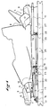
- Figure 1 shows a side view of an interface device according to a first embodiment of the invention.
- FIG. 2 represents in top view the device of FIG. 1.
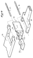
- FIG. 3 is a partial exploded perspective view of the connection between the probe and the various traction members for the device of FIG. 1.
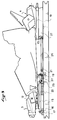
- Figure 4 shows a side view of the device of Figure 1 subjected to a vertical stress directed on the probe.
- FIGS. 5 to 10 show a side view of alternative embodiments of the invention, FIG. 8 being a top view of the device in FIG. 7.
- FIG. 1 represents a ski 1, seen from the side in its middle zone. Fastening elements 3 and 4 are mounted on the ski in this middle zone.
- the fastening elements 3 and 4 are of any suitable type.
- the front fastening element 3 has in known manner a jaw 5 for retaining the front end of the shoe.
- the jaw is carried by a body 6, and the body is itself mounted on a base plate 7 by which the binding element is assembled to the ski.
- the rear fastening element 4 has a jaw 8 carried by a body 9.
- the body 9 is slidably mounted along a base 10 shaped as a slide oriented in the longitudinal direction of the ski, and a spring, called recoil spring, resiliently pushes the body forward.
- Each fastening element 3, 4 is also associated with a support plate 12, 13, on which the shoe sole rests.
- the interface device which is the subject of the present invention is located in the middle area of the ski.
- the device comprises a probe movable in a substantially vertical direction.
- the probe is formed by the support plate 12 on which rests the front end of the shoe sole.
- the support plate 12 extends rearwardly the base 7 of the fixing element, and the assembly formed by the base and the support plate is mounted on a base plate 15 which is articulated in its front part around a transverse axis 16 carried by a bearing 17 connected integrally to the ski.
- the base plate 15 is presented as a generally rectangular plate which extends approximately in a horizontal plane, and it has on its upper surface a mounting area 18 on which is assembled the front fixing element.
- the base plate has an inextensible nature so as to transmit to the ski via the axis 16 and the bearing 17 the tensile stresses which are applied at its rear end.
- the articulation axis 16 is preferably raised relative to the upper surface of the ski, and the base plate 15 is itself raised relative to the upper surface of the ski.
- a damping means such as a block 20 of elastically deformable material is interposed between the upper surface of the ski and the base plate.
- the material can have damping or viscoelastic properties.
- the block 20 contributes to maintaining the base plate in a horizontal position, and it elastically opposes its rotation around the axis 16.
- any other articulation means other than an axis is suitable for ensuring the substantially vertical movement of the rear end of the base plate and of the probe.
- the rear part of the base plate is connected by an articulation around a transverse axis 21 to a rocker 22.
- the function of the rocker is to return the vertical forces applied to the probe 12 to the base plate in a horizontal direction.
- the rocker 22 has two approximately perpendicular branches, an approximately vertical branch 23 and an approximately horizontal branch 24.
- the hinge pin 21 with the base plate 15 is located at the top of the vertical branch 23.
- the horizontal branch 24 extends forward, and its front end is in support against a stud 25 which is integrally connected to the ski.
- the support of the rocker on the stud 25 is advantageously embodied by a transverse pin 24a situated at the front end of the branch 24. This pin facilitates the rotation of the rocker by pressing on the stud 25.
- the lower end of the vertical branch 23 of the rocker is retained in a horizontal direction by an elongate traction member 26 which comes from the rear of the ski.
- the traction member 26 is connected to the rocker 22 around an axis 19.
- the traction member 26 has an inextensible nature. It is connected rearwards to a rear base plate 27 which is located under the base 10 of the rear binding element, and which is secured to the ski. Its rear end penetrates into a housing 28 of the base plate 27, and it is assembled to the base plate by a pin 29.
- connection means is suitable.
- the traction member 26 works essentially in traction, it is possible to produce it in the form of an inextensible but deformable ribbon or cable.
- the articulation connections of the member 26 to the rocker and to the base plate 27 could be replaced by securing the ends of the ribbon or cable respectively to the rocker and to the base plate, the relative movement between these elements necessary for operation of the device resulting from the deformation of the ribbon or cable.
- the rear end of the traction member 26 could be secured not to the rear base plate 27, but directly to the ski in front of the base plate, or to the base 10 of the fixing element.
- the important thing is that the traction member 26 is connected to a fixed point on the ski. The height at which the traction member 26 is connected to the ski determines the lift arm with which a force conveyed by the traction member will be transmitted to the ski.
- a vertical stress exerted on the feeler forces the rocker to tilt relative to the stud 25 around the end of its horizontal branch 24.
- the articulation axis 21 is forced to move back, which induces in the base plate 15 a traction stress which is transmitted to the ski by the bearing 17.
- the traction member 26 transmits towards the rear of the ski a traction stress which in turn induces on the rear end of the ski a bending moment which tends to raise the end in question.
- Block 20 is also compressed.
- FIG. 3 illustrates such an operation of the device.
- the bending moments induced on the front and rear of the ski are more or less strong depending on the attitude of the axis 16 and the pin 29, respectively, relative to the upper surface of the ski.
- the bending moment induced on the rear of the ski is negligible, and only the front end of the ski is biased upwards .
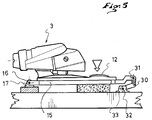
- FIG. 5 illustrates an alternative embodiment of the device which has just been described.
- the base 15 is connected to a rocker 30 by a transverse axis 31 in the same way as in the previous case.
- the rocker 30 is however articulated here at its base around a transverse axis 32 carried by a bearing 33 secured to the upper surface of the ski in front of the vertical line of the axis 31.
- the axis 32 is located below the attitude of the front axle 16.
- the axis 31 is higher than the axis 16 so that the stress applied by the base plate 15 to the axis 16 has a vertical component upwards.
- the rocker 30 and the axes 31 and 32 can be offset more or less far behind the front fixing element 3, which influences the nature and the intensity of the bending moment. applied to the front end of the ski.
- the rear binding element could be assembled to the ski according to the same connection method to generate on the rear of the ski a bending moment tending to raise this end.
- Figure 6 illustrates another alternative embodiment.
- the interface device is of the same type as that which has been described in relation to FIG. 1, with a front base plate 15, a rocker 22 of which one branch is in abutment against a stud 25, and a traction member 26 coming from the back.
- the main difference is in the mounting of the rear fixing element.
- the body 9 of the rear fastening element 4 is slidably mounted along a base shaped as a slide, and a recoil spring shown diagrammatically at 35 housed in the body 9 pushes the body forward, elastically. , taking support from a fixed point on the ski.
- a lock shown diagrammatically at 36, or another means also makes it possible to adjust the longitudinal position of the body as well as the intensity of this push back as a function of the length of the shoe. It is the lock which makes the connection between the body and the ski.
- the main function of the recoil spring is to produce an elastic pinch of the shoe sole between the front and rear fastening elements. This spring is also subjected to compression when the ski flexes, to absorb the differences in length between the ski which forms an arc, and the boot which forms the string of the arc.
- this recoil thrust generates in the ski a reaction which tends to oppose the bending of the ski.
- the intensity of this reaction increases with the compression of the recoil spring, that is to say with the flexural curvature of the ski.
- this reaction is channeled by an inextensible blade 38 which extends between the lock 36 and a fixed point on the ski situated on the front, for example the stud 25, or else in front of that -this.
- the blade 38 has in its rear part a series of notches 39, and the latch 36 has teeth which penetrate into part of these notches.
- This blade brings back the reaction of recoil to the front. It preferably brings this reaction back to the zone where the recoil stress has another component of opposite direction, that is to say in the zone of the front fixing element. Overall, the backward constraints therefore follow a circuit which hardly affects skiing.
- the slide 40 along which the body is slidably mounted is fixedly attached to the ski.
- the slide has on the front the support plate 13 on which the shoe sole rests.
- the backing plate could however be linked to the body.
- the traction member 26 As for the traction member 26, it is connected by the pin 26 to the front part 41 of the slide 40, that is to say to a fixed element on the ski.
- the device operates similarly to that of FIG. 1, with the difference that when the ski flexes due to the tensile stresses, the recoil spring does not tend to compress and to oppose this bending.
- the body of the rear element can move back because it is connected to the front of the middle zone of the ski by the blade 38 which forms the string of the arc in parallel with the sole of a shoe.
- the approximation of the rear binding element towards the front binding element is less than in the case of FIG. 1.
- the flexing effect of the ski is therefore improved by the fact that the spring recoil is not simply opposed to this bending.
- the base 7 of the front fixing element 3 is integrally connected to the ski.
- the base 10 of the rear binding element is integrally connected to the ski.
- the base 10 surmounts a base plate 47.
- the base 10 forms the slide along which the body 9 is slidably mounted, under the action of the recoil spring 35 which pushes it elastically towards the front.
- the spring 35 bears against the latch 36.
- the feeler is here formed by the front support plate 42 on which the front end of the shoe rests.
- the front support plate is mounted articulated in rotation about a transverse axis located towards the front of the plate.
- This axis can be materialized by an axis or a pin. It can also be fictitious.
- the rear part of the support plate 42 rests on the horizontal branch 43 of a rocker 44.
- the rocker 44 also has a vertical branch 45 which is articulated at its base around a transverse axis carried by a fixed bearing on ski.
- the bearing is for example formed by the rear part of the base 7.
- An inextensible blade 46 connects the top of the vertical branch 45 to the latch 36 of the rear fixing element. Like the blade 38, the blade 46 has notches in its rear part for the teeth of the lock. The lock is therefore connected integrally to the rear end of the blade 46.
- a stopper is used to block the lock backwards.
- this stop is formed by the cooperation of two lateral cutouts of the blade 49 and 50 with two lateral studs 51 and 52 which rise from the base plate 47.
- the cutouts have a length greater than that of the studs, to allow the blade to move forward relative to the studs.
- the blade releases its traction on the bolt, and the reaction of the recoil is gradually retransmitted to the ski by the base plate 47. The ends of the ski are again flexed against the snow.
- the front part of the device is similar to that of FIG. 6, with a base plate 15 articulated around an axis 16 to a bearing 17.
- the rear of the base plate 15 is connected to a rocker.
- the rear part of the device is similar to what has been described in connection with FIGS. 7 and 8, with the body 9 slidingly mounted along a slide 10 secured to the ski, a blade 53 on which the lock 36 is engaged , and the stop formed by the cutouts of the blade 53 cooperating with the studs 51, 52 of the base plate 47.
- the blade 53 is connected forwards to the base of the vertical branch of the rocker.
- a vertical stress on the feeler causes both a stress which is transmitted to the bearing 17 and to the ski in the form of a bending moment tending to raise the tip, and at the same time a transfer of the backward reaction towards the front of the middle zone of the ski, which improves the ability of the ski to flex in the direction d 'a raising of its extremities.
- FIG. 10 represents an interface device associated with a front fixing element 3 mounted on a base plate 55 connected integrally to the upper surface of the ski.
- the slide 10 of the rear fastening element is mounted articulated around a transverse axis 57 carried by a base plate 56 secured to the ski.
- a spring 58 or other elastic means elastically opposes the downward tilting of the slide 100.
- the front part of the base which includes the support plate 113, is kept raised, and it rests on the horizontal branch of a rocker 59.
- the rocker is articulated at its base relative to the ski, for example around 'an axis 60 carried by the base plate 56.
- a traction member 61 also connects the rocker 57 and the base plate 55, so as to transform the vertical stresses picked up by the support plate 113 into rearward tension stresses exerted on the base 55.
- the traction member could be connected to an element integral with the ski and distinct from the base 7 or from the base plate 55, for example a bearing such as the bearing 17.
Landscapes
- Footwear And Its Accessory, Manufacturing Method And Apparatuses (AREA)
- Buildings Adapted To Withstand Abnormal External Influences (AREA)
- Control Of Fluid Pressure (AREA)
- Steroid Compounds (AREA)
Applications Claiming Priority (2)
| Application Number | Priority Date | Filing Date | Title |
|---|---|---|---|
| FR9401898A FR2716119B1 (fr) | 1994-02-16 | 1994-02-16 | Dispositif interface pour modifier la répartition naturelle du ski sur la neige. |
| FR9401898 | 1994-02-16 |
Publications (2)
| Publication Number | Publication Date |
|---|---|
| EP0672437A1 true EP0672437A1 (de) | 1995-09-20 |
| EP0672437B1 EP0672437B1 (de) | 1999-06-09 |
Family
ID=9460244
Family Applications (1)
| Application Number | Title | Priority Date | Filing Date |
|---|---|---|---|
| EP95101029A Expired - Lifetime EP0672437B1 (de) | 1994-02-16 | 1995-01-26 | Vorrichtung zum Veränderen der natürlichen Druckverteilung eines Skis aus Schnee |
Country Status (4)
| Country | Link |
|---|---|
| EP (1) | EP0672437B1 (de) |
| AT (1) | ATE180985T1 (de) |
| DE (1) | DE69510113T2 (de) |
| FR (1) | FR2716119B1 (de) |
Citations (5)
| Publication number | Priority date | Publication date | Assignee | Title |
|---|---|---|---|---|
| EP0230989A2 (de) * | 1986-01-27 | 1987-08-05 | Hans Meyer | Federbrett für einen Ski |
| WO1993011838A1 (fr) * | 1991-12-11 | 1993-06-24 | Salomon S.A. | Dispositif visant a repartir la pression d'un ski sur une surface de glisse |
| WO1993014837A1 (fr) * | 1992-01-31 | 1993-08-05 | Salomon S.A. | Dispositif pour modifier la repartition d'un ski sur sa surface de glisse |
| EP0556610A2 (de) * | 1992-02-18 | 1993-08-25 | Salomon S.A. | Vorrichtung zum Verändern der natürlichen Druckverteilung eines Skis auf seine Gleitfläche |
| EP0567780A1 (de) * | 1992-04-17 | 1993-11-03 | Salomon S.A. | Ski mit Auflageplatte |
-
1994
- 1994-02-16 FR FR9401898A patent/FR2716119B1/fr not_active Expired - Fee Related
-
1995
- 1995-01-26 EP EP95101029A patent/EP0672437B1/de not_active Expired - Lifetime
- 1995-01-26 AT AT95101029T patent/ATE180985T1/de not_active IP Right Cessation
- 1995-01-26 DE DE69510113T patent/DE69510113T2/de not_active Expired - Fee Related
Patent Citations (5)
| Publication number | Priority date | Publication date | Assignee | Title |
|---|---|---|---|---|
| EP0230989A2 (de) * | 1986-01-27 | 1987-08-05 | Hans Meyer | Federbrett für einen Ski |
| WO1993011838A1 (fr) * | 1991-12-11 | 1993-06-24 | Salomon S.A. | Dispositif visant a repartir la pression d'un ski sur une surface de glisse |
| WO1993014837A1 (fr) * | 1992-01-31 | 1993-08-05 | Salomon S.A. | Dispositif pour modifier la repartition d'un ski sur sa surface de glisse |
| EP0556610A2 (de) * | 1992-02-18 | 1993-08-25 | Salomon S.A. | Vorrichtung zum Verändern der natürlichen Druckverteilung eines Skis auf seine Gleitfläche |
| EP0567780A1 (de) * | 1992-04-17 | 1993-11-03 | Salomon S.A. | Ski mit Auflageplatte |
Also Published As
| Publication number | Publication date |
|---|---|
| ATE180985T1 (de) | 1999-06-15 |
| FR2716119B1 (fr) | 1996-05-31 |
| EP0672437B1 (de) | 1999-06-09 |
| FR2716119A1 (fr) | 1995-08-18 |
| DE69510113D1 (de) | 1999-07-15 |
| DE69510113T2 (de) | 1999-12-09 |
Similar Documents
| Publication | Publication Date | Title |
|---|---|---|
| EP0530449B1 (de) | Vorrichtung zur Änderung der Druckverteilung eines Skis auf seiner Gleitfläche | |
| EP0556610B1 (de) | Vorrichtung zum Verändern der natürlichen Druckverteilung eines Skis auf seine Gleitfläche | |
| EP0624113B1 (de) | Vorrichtung zum verändern der natürlichen druckverteilung eines skis auf einer gleitfläche | |
| EP0617638B1 (de) | Einrichtung zur druckverteilung eines schis auf der gleitläche | |
| FR2687326A1 (fr) | Dispositif visant a modifier la repartition naturelle d'un ski sur sa surface de glisse, et ski equipe d'un tel dispositif. | |
| EP0658360B1 (de) | Vorrichtung zwischen Ski und Bindung | |
| EP0653231B1 (de) | Bindungselement für Skier | |
| EP0030175B1 (de) | Vorderbacken für Skibindung | |
| EP0641233B1 (de) | Vorrichtung zum verändern der natürlichen druckverteilung eines skis auf seinegleitfläche | |
| EP0634196B1 (de) | Bindungselement für einen alphinen Ski | |
| EP0599041B1 (de) | Trägerplatte zwischen Ski und Bindung | |
| EP1155717B1 (de) | Vorrichtung zum Erhöhen von wenigstens einer Bindung zur Verwendung auf einem Gleitbrett | |
| EP0672437B1 (de) | Vorrichtung zum Veränderen der natürlichen Druckverteilung eines Skis aus Schnee | |
| EP0660740B1 (de) | Vorrichtung zum verteilen des drucks eines skis auf einer gleitenden fläche | |
| EP0544063B1 (de) | Sicherheitsbindung für Alpinski | |
| EP0602350B1 (de) | Vorrichtung zwischen Ski und Bindung | |
| FR2624752A1 (fr) | Fixation de securite de ski alpin | |
| WO1992018211A1 (fr) | Ensemble de fixations declenchables pour une planche de glisse | |
| FR2766100A1 (fr) | Dispositif de freinage d'une planche de glisse | |
| FR2731358A1 (fr) | Dispositif destine a modifier la repartition naturelle d'un ski sur sa surface de glisse | |
| FR2690079A1 (fr) | Dispositif interface destiné à modifier la répartition naturelle de pression d'un ski sur sa surface de glisse. | |
| EP0934763A1 (de) | Vorderbacken einer Skibindung |
Legal Events
| Date | Code | Title | Description |
|---|---|---|---|
| PUAI | Public reference made under article 153(3) epc to a published international application that has entered the european phase |
Free format text: ORIGINAL CODE: 0009012 |
|
| AK | Designated contracting states |
Kind code of ref document: A1 Designated state(s): AT CH DE IT LI |
|
| 17P | Request for examination filed |
Effective date: 19951118 |
|
| 17Q | First examination report despatched |
Effective date: 19960429 |
|
| GRAG | Despatch of communication of intention to grant |
Free format text: ORIGINAL CODE: EPIDOS AGRA |
|
| GRAG | Despatch of communication of intention to grant |
Free format text: ORIGINAL CODE: EPIDOS AGRA |
|
| GRAH | Despatch of communication of intention to grant a patent |
Free format text: ORIGINAL CODE: EPIDOS IGRA |
|
| GRAH | Despatch of communication of intention to grant a patent |
Free format text: ORIGINAL CODE: EPIDOS IGRA |
|
| GRAA | (expected) grant |
Free format text: ORIGINAL CODE: 0009210 |
|
| AK | Designated contracting states |
Kind code of ref document: B1 Designated state(s): AT CH DE IT LI |
|
| PG25 | Lapsed in a contracting state [announced via postgrant information from national office to epo] |
Ref country code: IT Free format text: LAPSE BECAUSE OF FAILURE TO SUBMIT A TRANSLATION OF THE DESCRIPTION OR TO PAY THE FEE WITHIN THE PRE;WARNING: LAPSES OF ITALIAN PATENTS WITH EFFECTIVE DATE BEFORE 2007 MAY HAVE OCCURRED AT ANY TIME BEFORE 2007. THE CORRECT EFFECTIVE DATE MAY BE DIFFERENT FROM THE ONE RECORDED.SCRIBED TIME-LIMIT Effective date: 19990609 |
|
| REF | Corresponds to: |
Ref document number: 180985 Country of ref document: AT Date of ref document: 19990615 Kind code of ref document: T |
|
| REG | Reference to a national code |
Ref country code: CH Ref legal event code: EP |
|
| REF | Corresponds to: |
Ref document number: 69510113 Country of ref document: DE Date of ref document: 19990715 |
|
| PG25 | Lapsed in a contracting state [announced via postgrant information from national office to epo] |
Ref country code: LI Free format text: LAPSE BECAUSE OF NON-PAYMENT OF DUE FEES Effective date: 20000131 Ref country code: CH Free format text: LAPSE BECAUSE OF NON-PAYMENT OF DUE FEES Effective date: 20000131 |
|
| PLBE | No opposition filed within time limit |
Free format text: ORIGINAL CODE: 0009261 |
|
| STAA | Information on the status of an ep patent application or granted ep patent |
Free format text: STATUS: NO OPPOSITION FILED WITHIN TIME LIMIT |
|
| 26N | No opposition filed | ||
| REG | Reference to a national code |
Ref country code: CH Ref legal event code: PL |
|
| PGFP | Annual fee paid to national office [announced via postgrant information from national office to epo] |
Ref country code: AT Payment date: 20030113 Year of fee payment: 9 |
|
| PGFP | Annual fee paid to national office [announced via postgrant information from national office to epo] |
Ref country code: DE Payment date: 20030227 Year of fee payment: 9 |
|
| PG25 | Lapsed in a contracting state [announced via postgrant information from national office to epo] |
Ref country code: AT Free format text: LAPSE BECAUSE OF NON-PAYMENT OF DUE FEES Effective date: 20040126 |
|
| PG25 | Lapsed in a contracting state [announced via postgrant information from national office to epo] |
Ref country code: DE Free format text: LAPSE BECAUSE OF NON-PAYMENT OF DUE FEES Effective date: 20040803 |