EP0672460A1 - Installation de revêtement par pulvérisation - Google Patents
Installation de revêtement par pulvérisation Download PDFInfo
- Publication number
- EP0672460A1 EP0672460A1 EP94111109A EP94111109A EP0672460A1 EP 0672460 A1 EP0672460 A1 EP 0672460A1 EP 94111109 A EP94111109 A EP 94111109A EP 94111109 A EP94111109 A EP 94111109A EP 0672460 A1 EP0672460 A1 EP 0672460A1
- Authority
- EP
- European Patent Office
- Prior art keywords
- spray coating
- coating system
- guide rail
- spray
- axis
- Prior art date
- Legal status (The legal status is an assumption and is not a legal conclusion. Google has not performed a legal analysis and makes no representation as to the accuracy of the status listed.)
- Withdrawn
Links
Images


Classifications
-
- B—PERFORMING OPERATIONS; TRANSPORTING
- B05—SPRAYING OR ATOMISING IN GENERAL; APPLYING FLUENT MATERIALS TO SURFACES, IN GENERAL
- B05B—SPRAYING APPARATUS; ATOMISING APPARATUS; NOZZLES
- B05B13/00—Machines or plants for applying liquids or other fluent materials to surfaces of objects or other work by spraying, not covered by groups B05B1/00 - B05B11/00
- B05B13/02—Means for supporting work; Arrangement or mounting of spray heads; Adaptation or arrangement of means for feeding work
- B05B13/04—Means for supporting work; Arrangement or mounting of spray heads; Adaptation or arrangement of means for feeding work the spray heads being moved during spraying operation
- B05B13/0405—Means for supporting work; Arrangement or mounting of spray heads; Adaptation or arrangement of means for feeding work the spray heads being moved during spraying operation with reciprocating or oscillating spray heads
- B05B13/041—Means for supporting work; Arrangement or mounting of spray heads; Adaptation or arrangement of means for feeding work the spray heads being moved during spraying operation with reciprocating or oscillating spray heads with spray heads reciprocating along a straight line
- B05B13/0415—Means for supporting work; Arrangement or mounting of spray heads; Adaptation or arrangement of means for feeding work the spray heads being moved during spraying operation with reciprocating or oscillating spray heads with spray heads reciprocating along a straight line the angular position of the spray heads relative to the straight line being modified during the reciprocating movement
-
- B—PERFORMING OPERATIONS; TRANSPORTING
- B05—SPRAYING OR ATOMISING IN GENERAL; APPLYING FLUENT MATERIALS TO SURFACES, IN GENERAL
- B05B—SPRAYING APPARATUS; ATOMISING APPARATUS; NOZZLES
- B05B12/00—Arrangements for controlling delivery; Arrangements for controlling the spray area
- B05B12/08—Arrangements for controlling delivery; Arrangements for controlling the spray area responsive to condition of liquid or other fluent material to be discharged, of ambient medium or of target ; responsive to condition of spray devices or of supply means, e.g. pipes, pumps or their drive means
- B05B12/12—Arrangements for controlling delivery; Arrangements for controlling the spray area responsive to condition of liquid or other fluent material to be discharged, of ambient medium or of target ; responsive to condition of spray devices or of supply means, e.g. pipes, pumps or their drive means responsive to conditions of ambient medium or target, e.g. humidity, temperature position or movement of the target relative to the spray apparatus
- B05B12/122—Arrangements for controlling delivery; Arrangements for controlling the spray area responsive to condition of liquid or other fluent material to be discharged, of ambient medium or of target ; responsive to condition of spray devices or of supply means, e.g. pipes, pumps or their drive means responsive to conditions of ambient medium or target, e.g. humidity, temperature position or movement of the target relative to the spray apparatus responsive to presence or shape of target
Definitions
- the invention relates to a spray coating system according to the preamble of claim 1.
- a device for the automatic coating of objects with a spraying device which has a spray gun to which a program control device triggering successively different work steps is connected and with a transport device leading objects through certain coating positions.
- a clock generator generating clock signals synchronously with the feed movement of the transport device is coupled to the transport device.
- a sensor is provided, which is arranged at a certain distance from the spray device outside the spray area. Both the sensor and the clock generator are connected to a counter, which triggers the switching measures of the program control device.
- a spray coating system with an automatically controlled spraying device which is movable along a movement distance between a first and a last coating position, and has a transport device which serves for the objects to be coated, and one on the Spray device has passing section.
- a pulse generator is provided, which is coupled to the transport device and generates a certain number of pulses in synchronism with the movement thereof for each transport route section.
- a perception device is provided which perceives an object present on the transport device.
- a control device synchronizes the spray device to the pulses of the pulse generator and in dependence on signals from the sensing device.
- the spray devices can be moved back and forth to specific positions, for example by means of an electric motor, along a movement path parallel to the transport device.
- the speed of the spray device is matched to the speed of the transport device.
- the spraying device can be moved just as quickly or faster or slower than the transport device or in the opposite direction to the movement of the transport device, or can stand for certain periods of time while the transport device is continuously being moved.
- a complex point-to-point control is used.
- the synchronization is hereby achieved.
- a measuring device in particular an incremental encoder, is to be arranged on the lifting device on the one hand and on the conveyor belt on the other hand for the X and Y axes.
- the measurement signals obtained here have to be processed by a computer and solved by constructively complex attachments on the lifting device. In addition to weight problems, this means that existing systems can only be made more difficult or cannot be converted at all.
- DE-31 48 541 a large amount of technical programming is required. Furthermore, this system is also subject to a certain limitation of the lifting and conveying speed. According to DE-31 48 541 and also DE-30 14 114, a limited working speed can be described as a disadvantage, since the entire mass of the lifting device can be moved and leads to a certain inertia. According to the teaching of DE-31 48 541, a pistol axis is used. The information processing of the conveyor belt / lifting device and gun axis leads to a complex, computer-controlled system and is also subject to a certain limitation of the speed of the conveyor and lifting device and is only possible by measuring the three specific measuring units, namely conveying speed, lifting speed and gun movement.
- a device for spraying, in particular of flat workpieces moved by a transport device in which by means of automatically guided spray guns moved in a forcibly guided manner, with a scanning device for the contours of the workpieces, which signals the contours of the workpieces in enters an electronic memory for the automatic spray gun control, with a computer (microprocessor) which stores, for each raster step of the transport device, a series of individual signals recorded by the scanning device and extending transversely to the transport direction, the memory being synchronized with the transport device to form an electronically screened image (Workpiece grid) of the workpiece contour in the memory, and with a switching grid assigned to each spray gun, the position and extent of which can be changed, which change the switching position and / or the operating time in Controls dependency on workpiece shape and / or spray gun setting, the switching grid moving with the spray gun and the corresponding movement device of the spray gun and being switched on when at least one grid field of a workpiece grid is covered by at least one grid
- a photo cell recognition is used.
- the workpieces are recognized and the signals are passed on to the guns via the measuring device for the conveying speed.
- These measured variables are covered by a separate grid on the computer. This cover gives the area / contour to be sprayed out.
- the measuring device for the conveying speed always makes an enlargement or reduction of the own grid the recognizing grid.
- the present invention is therefore based on the object of providing a device which efficiently sweeps over the workpiece. This eliminates the disadvantages described.
- the present invention is based on the object of designing not only new systems but also existing systems inexpensively and efficiently in preparation and without restrictions on the conveying and lifting speeds.
- synchronization i. the synchronization path is arranged by means of a controlled motor and a track mounted on it, which automatically transfers the synchronization path to the gun carriage, and this arrangement is achieved by measuring the available conveying speed and the time in which the lifting system moves up and down during the switchover point. This time of the lifting speed with the conveying speed determines the synchronization path and can always be different.
- This synchronization path is achieved via a rail mounted on a central axis, and the actual spraying device is built on it, which is not rigid in itself but must be movable.
- the spray device has a frame which carries the spray guns and is arranged such that it can be moved along a guide rail, while the guide rail itself has a swivel or pendulum axis.
- a rectangular field is processed for each painting game, ie for each up and down stroke of the spray gun, areas of which are in this field and which do not require painting, of course, being cut out in a program-controlled manner.
- the rectangular field processing surprisingly achieves a qualitatively improved coating, which is moreover achieved in an efficient manner with regard to time and material consumption.
- the carrier frame has a gun holding shaft which varies the inclination of the outlet nozzle for the coating material with respect to the workpiece.
- the spray angle can thus be adjusted according to the requirements.
- the guide rail which is designed as a pendulum, can be aligned horizontally or vertically, so that the coating work can take place in the most varied of planes.
- a special feature of the invention is that it can work in almost all levels.
- the workpiece can be fed horizontally or vertically to the coating system, the actual guide rail then also being aligned vertically or horizontally.
- the carrier frame with the spray guns then not performing a lifting movement but a horizontal movement if the working plane has been chosen to be horizontal.
- the support frame then logically performs a stroke on the guide rail, which is also vertically aligned.
- the adjustment of the guide rail is preferably carried out via a motor control which operates the synchronization via the bearing axis of the guide rail.
- Limit switches are located at the apex and at the base of the guide rail, which detect the position of the carriage.
- Both manual and automatic adjustment of the synchronization is within the meaning of the invention, wherein in a special embodiment of the invention it is provided to automatically adjust the synchronization by measuring the conveying speed.
- Motors are arranged on the device as adjusting means for displacing the guide rail and the support frame.
- At least one motor is also provided for the positioning of the spray guns or for the adjustment of the holding shaft.
- the pivot axis of the guide rail lies on the central axis of the object to be coated or the surface to be coated.
- the adjusting motor for the guide rail is arranged on the central axis.
- this adjustment motor for the guide rail is arranged at a distance from the pivot axis, so that a lever path is formed.
- the adjustment motor for the guide rail is arranged at its bottom end and the guide rail is provided with an adjusting means which is designed, for example, as a toothed rack, in particular an arc-shaped toothed rack, and meshes on a pinion of the adjusting motor.
- the radius of the arc is selected to the extent that the distance between the pivot axis and the end of the Guide rail is.
- Corresponding means are provided on the device so that the support frame for the spray guns always remains horizontal during the pivoting movement of the guide rail.
- means for linear lifting movement of the support frame along the lifting device are provided, the support frame being horizontally displaceable relative to these means, so that with a simultaneous linear lifting movement a horizontal movement is ensured when the guide rail is pivoted.
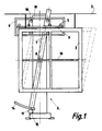
- the transport system 2 can be designed as a crane runway on which the objects 3 to be coated, here windows, are suspended.
- the objects 3 to be coated are then guided past the spray device 4 via the transport system 2.
- the spray device 4 or the spray guns 5 also moves in or against the transport direction of the object 3 to be coated during the upward or downward stroke, in a special, unique way .
- the spray device 4 is positioned stationary and to arrange the spray guns 5 on a frame 6 which can be moved vertically on a guide rail 7, for example.
- the guide rail 7 is mounted on an axis 8 about which the guide rail 7 can be pivoted. A further movement is thus created during the downward movement or upward movement, but independently of this for the frame 6 or the spray guns 5.
- FIG. 3 shows the actual spray application for pistols 1 and 2.
- the lifting device moves from the lower switching point to the upper switching point for 6 seconds.
- the workpiece shifts by 500mm.
- This shifting or synchronization is achieved automatically with a motor-controlled, central axis mounted rail, and is always switched on again when the lifting device moves to the end positions (top and bottom).
- the synchronization path can be set manually or automatically or can be set automatically by measuring the conveying speed.
- the adjusting motor 11 for the guide rail 7 is arranged at the bottom end of the latter.
- the adjusting motor 11 communicates with an adjusting means 14 arranged on the guide rail 7.
- a pinion 15 which is applied to the motor 11 and which is designed as a toothed rack is particularly suitable here Adjusting means 14 combs.
- the adjusting means 14 has an arcuate shape.
- the spray guns 5 are arranged on a gun holding shaft 9 which is rotatably mounted and is rotated according to the requirements, so that the outlet opening of the spray guns 5 changes the direction of travel or adapts the workpiece surface in a suitable manner.
- the pistol holding shaft 9 works in this exemplary embodiment with a lever joint 16, which in each case moves the spray head or the spray pistol 5 with their outlet openings into the desired position, so that the spray jet 17 goes up or down points below or is in a middle position.
- the device according to the invention serves to work pieces, e.g. Coating windows in their true size and deliberately working out difficult corner areas. Furthermore, the design is designed so that existing systems can be converted.
- the pistol axis is also always pivoted in the direction of travel, this has the advantage that the efficiency increases significantly. This synchronization enables considerable improvements in quality to be achieved on the workpiece and also considerable material savings.
Landscapes
- Spray Control Apparatus (AREA)
Applications Claiming Priority (2)
| Application Number | Priority Date | Filing Date | Title |
|---|---|---|---|
| DE4409269 | 1994-03-18 | ||
| DE19944409269 DE4409269C2 (de) | 1994-03-18 | 1994-03-18 | Sprühbeschichtungsanlage |
Publications (1)
| Publication Number | Publication Date |
|---|---|
| EP0672460A1 true EP0672460A1 (fr) | 1995-09-20 |
Family
ID=6513158
Family Applications (1)
| Application Number | Title | Priority Date | Filing Date |
|---|---|---|---|
| EP94111109A Withdrawn EP0672460A1 (fr) | 1994-03-18 | 1994-07-16 | Installation de revêtement par pulvérisation |
Country Status (2)
| Country | Link |
|---|---|
| EP (1) | EP0672460A1 (fr) |
| DE (1) | DE4409269C2 (fr) |
Cited By (6)
| Publication number | Priority date | Publication date | Assignee | Title |
|---|---|---|---|---|
| ITMI20100540A1 (it) * | 2010-03-31 | 2011-10-01 | Elmag Spa | "apparecchiatura per la verniciatura o spruzzatura automatizzata di pezzi" |
| CN108128504A (zh) * | 2017-12-18 | 2018-06-08 | 华南智能机器人创新研究院 | 一种动态调整自动喷码扫码机 |
| CN114226120A (zh) * | 2021-12-28 | 2022-03-25 | 浙江三旭智能制造有限公司 | 全自动多工位在线喷涂线 |
| CN114713423A (zh) * | 2022-04-12 | 2022-07-08 | 南昌大学 | 一种仿形机构 |
| CN115178413A (zh) * | 2022-07-07 | 2022-10-14 | 南京鑫之鸿环保科技有限公司 | 循环轨道式自动涂装流水线 |
| CN116408226A (zh) * | 2021-12-31 | 2023-07-11 | 中集安瑞环科技股份有限公司 | 喷涂装置及喷涂系统 |
Citations (6)
| Publication number | Priority date | Publication date | Assignee | Title |
|---|---|---|---|---|
| FR1292166A (fr) * | 1961-06-15 | 1962-04-27 | Carrier Engineering Co Ltd | Améliorations relatives aux machines à revêtir |
| US4024836A (en) * | 1976-03-22 | 1977-05-24 | Owens-Illinois, Inc. | Traversing lehr spray |
| FR2467639A1 (fr) * | 1979-10-18 | 1981-04-30 | Cepem | Procede et dispositif de revetement d'objets suivant des bandes verticales |
| EP0108716A2 (fr) * | 1982-11-09 | 1984-05-16 | Ametex Ag | Installation de revêtement par pulvérisation |
| EP0323316A2 (fr) * | 1987-12-24 | 1989-07-05 | Saint-Gobain Vitrage International | Procédé de formation de couches régulières par pulvérisation de compositions liquides sur un substrat et dispositif pour la mise en oeuvre de ce procédé |
| DE9404585U1 (de) * | 1994-03-16 | 1994-05-26 | Dirwimmer, Franz Xaver, 94428 Eichendorf | Sprühbeschichtungsanlage |
Family Cites Families (4)
| Publication number | Priority date | Publication date | Assignee | Title |
|---|---|---|---|---|
| GB1113959A (en) * | 1964-12-08 | 1968-05-15 | Ici Australia Ltd | Method of distributing a liquid onto a sheet |
| DE3014114C2 (de) * | 1980-04-12 | 1982-04-29 | Gema AG Apparatebau, 9015 St. Gallen | Einrichtung zum automatischen Beschichten von Gegenständen mit einer Spritzvorrichtung |
| DE3813058A1 (de) * | 1988-04-19 | 1989-11-09 | Devilbiss Gmbh | Frei programmierbare konturmaschine |
| DE4023176A1 (de) * | 1990-07-20 | 1992-01-23 | Behr Industrieanlagen | Verfahren und einrichtung zum automatischen erzeugen von parallelen bahnen |
-
1994
- 1994-03-18 DE DE19944409269 patent/DE4409269C2/de not_active Expired - Fee Related
- 1994-07-16 EP EP94111109A patent/EP0672460A1/fr not_active Withdrawn
Patent Citations (6)
| Publication number | Priority date | Publication date | Assignee | Title |
|---|---|---|---|---|
| FR1292166A (fr) * | 1961-06-15 | 1962-04-27 | Carrier Engineering Co Ltd | Améliorations relatives aux machines à revêtir |
| US4024836A (en) * | 1976-03-22 | 1977-05-24 | Owens-Illinois, Inc. | Traversing lehr spray |
| FR2467639A1 (fr) * | 1979-10-18 | 1981-04-30 | Cepem | Procede et dispositif de revetement d'objets suivant des bandes verticales |
| EP0108716A2 (fr) * | 1982-11-09 | 1984-05-16 | Ametex Ag | Installation de revêtement par pulvérisation |
| EP0323316A2 (fr) * | 1987-12-24 | 1989-07-05 | Saint-Gobain Vitrage International | Procédé de formation de couches régulières par pulvérisation de compositions liquides sur un substrat et dispositif pour la mise en oeuvre de ce procédé |
| DE9404585U1 (de) * | 1994-03-16 | 1994-05-26 | Dirwimmer, Franz Xaver, 94428 Eichendorf | Sprühbeschichtungsanlage |
Cited By (8)
| Publication number | Priority date | Publication date | Assignee | Title |
|---|---|---|---|---|
| ITMI20100540A1 (it) * | 2010-03-31 | 2011-10-01 | Elmag Spa | "apparecchiatura per la verniciatura o spruzzatura automatizzata di pezzi" |
| CN108128504A (zh) * | 2017-12-18 | 2018-06-08 | 华南智能机器人创新研究院 | 一种动态调整自动喷码扫码机 |
| CN108128504B (zh) * | 2017-12-18 | 2024-02-27 | 华南智能机器人创新研究院 | 一种动态调整自动喷码扫码机 |
| CN114226120A (zh) * | 2021-12-28 | 2022-03-25 | 浙江三旭智能制造有限公司 | 全自动多工位在线喷涂线 |
| CN116408226A (zh) * | 2021-12-31 | 2023-07-11 | 中集安瑞环科技股份有限公司 | 喷涂装置及喷涂系统 |
| CN114713423A (zh) * | 2022-04-12 | 2022-07-08 | 南昌大学 | 一种仿形机构 |
| CN115178413A (zh) * | 2022-07-07 | 2022-10-14 | 南京鑫之鸿环保科技有限公司 | 循环轨道式自动涂装流水线 |
| CN115178413B (zh) * | 2022-07-07 | 2023-05-26 | 南京鑫之鸿环保科技有限公司 | 循环轨道式自动涂装流水线 |
Also Published As
| Publication number | Publication date |
|---|---|
| DE4409269C2 (de) | 1998-02-12 |
| DE4409269A1 (de) | 1995-09-21 |
Similar Documents
| Publication | Publication Date | Title |
|---|---|---|
| DE3014114C2 (de) | Einrichtung zum automatischen Beschichten von Gegenständen mit einer Spritzvorrichtung | |
| DE10149424B4 (de) | Maschine für das automatische Anstreichen von Platten oder anderen Gegenständen | |
| EP0631525B1 (fr) | Procede d'enduction automatique d'objets au moyen d'un pulverisateur | |
| DE3725681A1 (de) | Vorrichtung zum spritz-beschichten | |
| DE60123924T2 (de) | Spritzvorrichtung, insbesondere für eine Lackierkabine für Fahrzeugkarosserien | |
| EP0496983A1 (fr) | Appareil pour nettoyer et enlever des couches de peinture des objets à grande surface | |
| EP0415154A1 (fr) | Méthode pour inspecter des objets à partir de différents angles visuels | |
| DE2159377C3 (de) | Anlage zum Beschichten der Oberfläche einer Folge von relativ zur Anlage bewegbaren Gegenständen | |
| EP0650398A1 (fr) | Dispositif de pulverisation. | |
| EP0672460A1 (fr) | Installation de revêtement par pulvérisation | |
| DE1652422A1 (de) | Selbsttaetige UEberzugsanlage | |
| DE4032719A1 (de) | Einrichtung zum auftragen von produkten, wie farben oder lacke, mit hilfe von spritzpistolen auf unregelmaessig geformte teile | |
| EP1419824B1 (fr) | Dispositif de revêtement de pièces avec poudre | |
| DE3014500A1 (de) | Vorrichtung zum spritzen, insbesondere von flaechigen werkstuecken | |
| EP3190094B1 (fr) | Dispositif de fabrication de produits en verre creux | |
| EP0727298A1 (fr) | Méthode pour enduire de matière visqueux les bandes de bordure et les parties en coin | |
| DE10119906B4 (de) | Farbspritzanlage | |
| EP1784901B1 (fr) | Procede pour recouvrir en particulier pour peindre des articles, en particulier des carrosseries de vehicules | |
| DE9404585U1 (de) | Sprühbeschichtungsanlage | |
| DE19637730C1 (de) | Verfahren zum automatischen Beschichten von Werkstücken | |
| DE2534224C2 (de) | Verfahren zum Identifizieren eines Werkstückes und Vorrichtung zum Durchführen des Verfahrens | |
| DE29721203U1 (de) | Vorrichtung zum Palettieren von Stückgutlagen | |
| DE19953281A1 (de) | Stanz-, Biege- und Montageautomat mit Rundschalttisch | |
| DE19645872C2 (de) | Vorrichtung zum Aufbringen von Dichtungsmassen auf unrunde Deckelrandkonturen | |
| EP1171244A1 (fr) | Procede et dispositif pour la peinture de carrosseries de vehicules |
Legal Events
| Date | Code | Title | Description |
|---|---|---|---|
| PUAI | Public reference made under article 153(3) epc to a published international application that has entered the european phase |
Free format text: ORIGINAL CODE: 0009012 |
|
| AK | Designated contracting states |
Kind code of ref document: A1 Designated state(s): AT BE CH DE DK ES FR GB IE IT LI NL SE |
|
| 17P | Request for examination filed |
Effective date: 19960531 |
|
| STAA | Information on the status of an ep patent application or granted ep patent |
Free format text: STATUS: THE APPLICATION IS DEEMED TO BE WITHDRAWN |
|
| 18D | Application deemed to be withdrawn |
Effective date: 19970201 |