EP0672833A2 - Hochgeschwindigkeitspumpe für Wirbelbäder - Google Patents
Hochgeschwindigkeitspumpe für Wirbelbäder Download PDFInfo
- Publication number
- EP0672833A2 EP0672833A2 EP95850062A EP95850062A EP0672833A2 EP 0672833 A2 EP0672833 A2 EP 0672833A2 EP 95850062 A EP95850062 A EP 95850062A EP 95850062 A EP95850062 A EP 95850062A EP 0672833 A2 EP0672833 A2 EP 0672833A2
- Authority
- EP
- European Patent Office
- Prior art keywords
- motor
- pump
- impeller
- speed
- inducerpeller
- Prior art date
- Legal status (The legal status is an assumption and is not a legal conclusion. Google has not performed a legal analysis and makes no representation as to the accuracy of the status listed.)
- Withdrawn
Links
Images
Classifications
-
- H—ELECTRICITY
- H02—GENERATION; CONVERSION OR DISTRIBUTION OF ELECTRIC POWER
- H02K—DYNAMO-ELECTRIC MACHINES
- H02K23/00—DC commutator motors or generators having mechanical commutator; Universal AC/DC commutator motors
- H02K23/66—Structural association with auxiliary electric devices influencing the characteristic of, or controlling, the machine, e.g. with impedances or switches
-
- F—MECHANICAL ENGINEERING; LIGHTING; HEATING; WEAPONS; BLASTING
- F04—POSITIVE - DISPLACEMENT MACHINES FOR LIQUIDS; PUMPS FOR LIQUIDS OR ELASTIC FLUIDS
- F04D—NON-POSITIVE-DISPLACEMENT PUMPS
- F04D25/00—Pumping installations or systems
- F04D25/02—Units comprising pumps and their driving means
- F04D25/06—Units comprising pumps and their driving means the pump being electrically driven
-
- A—HUMAN NECESSITIES
- A61—MEDICAL OR VETERINARY SCIENCE; HYGIENE
- A61H—PHYSICAL THERAPY APPARATUS, e.g. DEVICES FOR LOCATING OR STIMULATING REFLEX POINTS IN THE BODY; ARTIFICIAL RESPIRATION; MASSAGE; BATHING DEVICES FOR SPECIAL THERAPEUTIC OR HYGIENIC PURPOSES OR SPECIFIC PARTS OF THE BODY
- A61H33/00—Bathing devices for special therapeutic or hygienic purposes
- A61H33/60—Components specifically designed for the therapeutic baths of groups A61H33/00
-
- F—MECHANICAL ENGINEERING; LIGHTING; HEATING; WEAPONS; BLASTING
- F04—POSITIVE - DISPLACEMENT MACHINES FOR LIQUIDS; PUMPS FOR LIQUIDS OR ELASTIC FLUIDS
- F04D—NON-POSITIVE-DISPLACEMENT PUMPS
- F04D13/00—Pumping installations or systems
- F04D13/02—Units comprising pumps and their driving means
- F04D13/06—Units comprising pumps and their driving means the pump being electrically driven
-
- F—MECHANICAL ENGINEERING; LIGHTING; HEATING; WEAPONS; BLASTING
- F04—POSITIVE - DISPLACEMENT MACHINES FOR LIQUIDS; PUMPS FOR LIQUIDS OR ELASTIC FLUIDS
- F04D—NON-POSITIVE-DISPLACEMENT PUMPS
- F04D29/00—Details, component parts, or accessories
- F04D29/08—Sealings
- F04D29/10—Shaft sealings
- F04D29/12—Shaft sealings using sealing-rings
- F04D29/126—Shaft sealings using sealing-rings especially adapted for liquid pumps
-
- F—MECHANICAL ENGINEERING; LIGHTING; HEATING; WEAPONS; BLASTING
- F04—POSITIVE - DISPLACEMENT MACHINES FOR LIQUIDS; PUMPS FOR LIQUIDS OR ELASTIC FLUIDS
- F04D—NON-POSITIVE-DISPLACEMENT PUMPS
- F04D29/00—Details, component parts, or accessories
- F04D29/08—Sealings
- F04D29/16—Sealings between pressure and suction sides
- F04D29/165—Sealings between pressure and suction sides especially adapted for liquid pumps
- F04D29/167—Sealings between pressure and suction sides especially adapted for liquid pumps of a centrifugal flow wheel
-
- F—MECHANICAL ENGINEERING; LIGHTING; HEATING; WEAPONS; BLASTING
- F04—POSITIVE - DISPLACEMENT MACHINES FOR LIQUIDS; PUMPS FOR LIQUIDS OR ELASTIC FLUIDS
- F04D—NON-POSITIVE-DISPLACEMENT PUMPS
- F04D29/00—Details, component parts, or accessories
- F04D29/18—Rotors
- F04D29/22—Rotors specially for centrifugal pumps
- F04D29/2261—Rotors specially for centrifugal pumps with special measures
- F04D29/2277—Rotors specially for centrifugal pumps with special measures for increasing NPSH or dealing with liquids near boiling-point
-
- F—MECHANICAL ENGINEERING; LIGHTING; HEATING; WEAPONS; BLASTING
- F04—POSITIVE - DISPLACEMENT MACHINES FOR LIQUIDS; PUMPS FOR LIQUIDS OR ELASTIC FLUIDS
- F04D—NON-POSITIVE-DISPLACEMENT PUMPS
- F04D29/00—Details, component parts, or accessories
- F04D29/26—Rotors specially for elastic fluids
- F04D29/28—Rotors specially for elastic fluids for centrifugal or helico-centrifugal pumps for radial-flow or helico-centrifugal pumps
- F04D29/281—Rotors specially for elastic fluids for centrifugal or helico-centrifugal pumps for radial-flow or helico-centrifugal pumps for fans or blowers
-
- F—MECHANICAL ENGINEERING; LIGHTING; HEATING; WEAPONS; BLASTING
- F04—POSITIVE - DISPLACEMENT MACHINES FOR LIQUIDS; PUMPS FOR LIQUIDS OR ELASTIC FLUIDS
- F04D—NON-POSITIVE-DISPLACEMENT PUMPS
- F04D29/00—Details, component parts, or accessories
- F04D29/40—Casings; Connections of working fluid
- F04D29/42—Casings; Connections of working fluid for radial or helico-centrifugal pumps
- F04D29/4206—Casings; Connections of working fluid for radial or helico-centrifugal pumps especially adapted for elastic fluid pumps
- F04D29/422—Discharge tongues
-
- F—MECHANICAL ENGINEERING; LIGHTING; HEATING; WEAPONS; BLASTING
- F04—POSITIVE - DISPLACEMENT MACHINES FOR LIQUIDS; PUMPS FOR LIQUIDS OR ELASTIC FLUIDS
- F04D—NON-POSITIVE-DISPLACEMENT PUMPS
- F04D29/00—Details, component parts, or accessories
- F04D29/40—Casings; Connections of working fluid
- F04D29/42—Casings; Connections of working fluid for radial or helico-centrifugal pumps
- F04D29/426—Casings; Connections of working fluid for radial or helico-centrifugal pumps especially adapted for liquid pumps
- F04D29/4273—Casings; Connections of working fluid for radial or helico-centrifugal pumps especially adapted for liquid pumps suction eyes
-
- F—MECHANICAL ENGINEERING; LIGHTING; HEATING; WEAPONS; BLASTING
- F04—POSITIVE - DISPLACEMENT MACHINES FOR LIQUIDS; PUMPS FOR LIQUIDS OR ELASTIC FLUIDS
- F04D—NON-POSITIVE-DISPLACEMENT PUMPS
- F04D29/00—Details, component parts, or accessories
- F04D29/58—Cooling; Heating; Diminishing heat transfer
- F04D29/5806—Cooling the drive system
-
- H—ELECTRICITY
- H02—GENERATION; CONVERSION OR DISTRIBUTION OF ELECTRIC POWER
- H02K—DYNAMO-ELECTRIC MACHINES
- H02K5/00—Casings; Enclosures; Supports
- H02K5/04—Casings or enclosures characterised by the shape, form or construction thereof
- H02K5/08—Insulating casings
-
- A—HUMAN NECESSITIES
- A61—MEDICAL OR VETERINARY SCIENCE; HYGIENE
- A61H—PHYSICAL THERAPY APPARATUS, e.g. DEVICES FOR LOCATING OR STIMULATING REFLEX POINTS IN THE BODY; ARTIFICIAL RESPIRATION; MASSAGE; BATHING DEVICES FOR SPECIAL THERAPEUTIC OR HYGIENIC PURPOSES OR SPECIFIC PARTS OF THE BODY
- A61H33/00—Bathing devices for special therapeutic or hygienic purposes
Definitions
- This invention relates to high speed pumps, and more particularly to high speed pumps for Whirlpool and Spa applications.
- Whirlpool pumps provide flow and pressure to the liquid to be circulated in the normal manner consistent with single stage centrifugal, Kinetic pumps, of radial vane, closed impeller construction. Substantially all of the whirlpool pumps are driven by various types of induction motors, as is the case with most electric motor driven centrifugal pumps.
- the biggest shortcoming with the above mentioned current devices is the inherent relative high cost of the motor.
- the size and, therefore, cost of the motor is inversely related to the motor speed. The higher the speed the smaller the size and the lower the cost.
- the maximum motor speed on normal household A. C. current is 3600 RPM, based on an A.C. induction motor, with the minimum number (two) of motor poles and 60 cycles per second current frequency in the USA.
- Devices have been developed for induction type A.C. motors which can vary the cycle frequency (and therefore motor speed) up or down, however, this does not reduce, but rather increase the complexity and cost of the motor plus controls package.
- An object of the invention is to provide an improved pump which operates at high speed.
- a series wound universal motor is used to power, thru a direct drive (close coupled), a high speed centrifugal impeller, to speeds in the range of 4000 RPM to 9000 RPM, for whirlpool and Spa applications.
- a universal motor is cheaper than a single speed, two speed or variable speed induction motor, due to the higher speed and subsequent smaller motor size.
- variable speed is easily accomplished with a universal motor by just varying only the voltage to the motor, and variable speed is a desirable option in the Whirlpool and Spa market.
- a feature of the invention is that the leading edge of the impeller vanes, extends forward along the axial portion of the front shroud, toward the incoming flow stream (impeller eye) to form a female "inducerpeller".
- the female inducerpeller portion of the impeller vane has an extensive sweep back angle to the incoming flow, approximately five to fifteen degrees to the impeller axis.
- Inducers male and female
- impellers which extend the full impeller vanes axially into the impeller eye to form a male "inducerpeller" to achieve the same improved suction performance as a separate inducer with an impeller.
- the inventive inducerpeller only extends the portion of the vane attached to and near the front shroud into the impeller eye to form a female "inducerpeller". Cavitation normally starts where the leading edge of the impeller vane meets the front shroud. This achieves the required improved suction performance (for a high speed universal motor direct drive (in the 4000 RPM to 9000 RPM range) without increasing the cost or size of the pump, as would be required with a separate inducer, or operating the pump at slow speed.
- female inducerpeller vane extensions are known in the industrial pump industry, an inventive feature is its coupling with a universal motor driven pump for Whirlpool and Spa applications, and particularly with molded plastic impellers.
- Yet another feature of this invention is the two step front impeller seal wear ring (surface) construction to reduce the recirculation leakage flow into the pump suction. Not only does this increase pump efficiency but it improves the suction performance of the pump. This coupled with the described inducerpeller above, permits the pump to be operated at high speeds.
- two step front impeller seal wear ring (surface) construction is known for use with industrial pumps, an inventive feature is its use with universal motor driven pumps in the whirlpool and Spa applications, especially when coupled with the female inducerpeller vane extensions previously discussed.
- a still further feature of this invention is a unique combination of mechanical seal components which permit dry running of the mechanical seal to speeds up to 18,000 RPM.
- This feature is achieved by using a rotating ceramic component on the back side of a plastic impeller, which has a metal band around the outer circumference. This metal band dissipates a sufficient amount of heat to allow the seal and impeller to survive for hours when run dry at these high speeds. This is even a bigger problem with universal motors, since they speed up when unloaded.
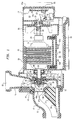
- the apparatus includes a suction cover 11, suction inlet 12, insert 13, and self-draining channel 14.
- a O-ring 16 is positioned between cover 11 and casing 18 having an outlet 19.
- Cover 11 and casing 18 are mounted to universal motor housing 20 by self taping screws in a standard manner.
- the universal motor includes a stator 22 and an armature 24.
- the armature 24 includes a commutator 25, and a shaft 26 having a threaded end 27 and a splined end 28.
- the commutator brushes for the universal motor are located in the housing 20 in a plane perpendicular to the cross-sectional view.
- Inducerpeller 30 Threaded on shaft end 27 is an inducerpeller 30 having mounted thereon a rubber boot 31, ceramic ring 32, and metal retaining ring 33 which form part of a mechanical seal.
- the other part of the mechanical seal includes a carbon seal ring 35, rubber boot 36, spring 37, and retaining cup 38.
- An O-ring 39 is positioned between cup 38 and casing 18.
- Inducerpeller 30 has two step front surfaces 40, 41 which run with a clearance between the complementary inner surfaces 13a, 13b of insert 13 to provide an impeller seal wear ring surface to reduce recirculation leakage flow into the pump suction.
- the inducerpeller has a vane 42 with a vane portion 42a which extends forward along the axial portion of the front shroud 40a, and sweeps back an angle of approximately 5° to 15° to the impeller axis to improve suction performance.
- a slinger 44 is mounted on shaft 26 adjacent bearing hub 46 of housing 20.
- Bearings 48, rotatably mount shaft 26 in hub 46, and bearings 50 rotatably mount the splined end 28 to housing bearing surface 52, and bearing 50 is retained on housing bearing surface 52 by means of strap 53.
- a fan 55 is spline mounted on the spline end 28 of shaft 26.
- An elastomeric motor mounting foot 60 encloses a compartment 61, in which may be mounted a circuit board 62 for mounting electrical components 62a, b for motor speed control.
- Back plate 65 encloses another compartment 66 in which may be mounted another circuit board 67 for mounting other of the electrical components 67a, b to control motor speed.
- Terminals 70, 71, 72 are used to connect leads to and from circuit boards and power source.
- Power leads (not shown) are coupled through opening 21 in housing 20 in known manner.
- Back plate 65 may be metal to facilitate heat transfer though fins 65a from circuit board 67 which may be the high power circuit board of the control requiring the most heat dissipation.
- cover 11, insert 13, casing 18, housing 20, inducerpeller 30, fan 55, and mounting foot 60 are made of plastic suitable for injection molding.
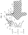
- FIG. 2 an enlarged partial sectional view shows the inducerpeller 30 of Figure 1.
- the impeller 30 has mounted on its hub 30a, a rubber boot 31, a ceramic ring seal component 32, and a metal seal band 33.
- the metal band dissipates sufficient heat to allow the seal and inducerpeller to run dry for a number of hours at high speeds.
- the front shroud 30b has stepped front surface wear ring surfaces 40, 41.
- the vane 42 has a leading edge portion (shown in shaded lines) 42a which flows smoothly into the axial impeller eye portion 30 C and sweeps backward at angle of approximately 5° - 15° to the axis of the inducerpeller.
- the leading edge portion facilitates smooth fluid flow transition represented by arrows 43 to 43a.
Landscapes
- Engineering & Computer Science (AREA)
- Mechanical Engineering (AREA)
- General Engineering & Computer Science (AREA)
- Health & Medical Sciences (AREA)
- Public Health (AREA)
- Power Engineering (AREA)
- Life Sciences & Earth Sciences (AREA)
- Epidemiology (AREA)
- Pain & Pain Management (AREA)
- Physical Education & Sports Medicine (AREA)
- Rehabilitation Therapy (AREA)
- Animal Behavior & Ethology (AREA)
- General Health & Medical Sciences (AREA)
- Veterinary Medicine (AREA)
- Thermal Sciences (AREA)
- Physics & Mathematics (AREA)
- Structures Of Non-Positive Displacement Pumps (AREA)
- Control Of Non-Positive-Displacement Pumps (AREA)
Applications Claiming Priority (3)
| Application Number | Priority Date | Filing Date | Title |
|---|---|---|---|
| US07/607,179 US5156535A (en) | 1990-10-31 | 1990-10-31 | High speed whirlpool pump |
| US607179 | 1990-10-31 | ||
| EP91850247A EP0484305B1 (de) | 1990-10-31 | 1991-10-09 | Hochgeschwindigkeitspumpe für Wirbelbäder |
Related Parent Applications (1)
| Application Number | Title | Priority Date | Filing Date |
|---|---|---|---|
| EP91850247.7 Division | 1991-10-09 |
Publications (2)
| Publication Number | Publication Date |
|---|---|
| EP0672833A2 true EP0672833A2 (de) | 1995-09-20 |
| EP0672833A3 EP0672833A3 (de) | 1996-04-17 |
Family
ID=24431159
Family Applications (2)
| Application Number | Title | Priority Date | Filing Date |
|---|---|---|---|
| EP91850247A Expired - Lifetime EP0484305B1 (de) | 1990-10-31 | 1991-10-09 | Hochgeschwindigkeitspumpe für Wirbelbäder |
| EP95850062A Withdrawn EP0672833A3 (de) | 1990-10-31 | 1991-10-09 | Hochgeschwindigkeitspumpe für Wirbelbäder. |
Family Applications Before (1)
| Application Number | Title | Priority Date | Filing Date |
|---|---|---|---|
| EP91850247A Expired - Lifetime EP0484305B1 (de) | 1990-10-31 | 1991-10-09 | Hochgeschwindigkeitspumpe für Wirbelbäder |
Country Status (8)
| Country | Link |
|---|---|
| US (1) | US5156535A (de) |
| EP (2) | EP0484305B1 (de) |
| JP (1) | JPH086716B2 (de) |
| KR (1) | KR950013778B1 (de) |
| CA (1) | CA2054556C (de) |
| DE (1) | DE69119698T2 (de) |
| ES (1) | ES2088479T3 (de) |
| TW (1) | TW197486B (de) |
Cited By (1)
| Publication number | Priority date | Publication date | Assignee | Title |
|---|---|---|---|---|
| DE10050108A1 (de) * | 2000-10-09 | 2002-06-06 | Allweiler Ag | Laufrad für eine Kreiselpumpe |
Families Citing this family (90)
| Publication number | Priority date | Publication date | Assignee | Title |
|---|---|---|---|---|
| DE4237971B4 (de) † | 1992-11-11 | 2004-05-06 | Unaxis Deutschland Holding Gmbh | Vakuumpumpe mit Wandler |
| JPH06159520A (ja) * | 1992-11-13 | 1994-06-07 | Eagle Ind Co Ltd | メカニカルシール |
| DE4304149C1 (de) * | 1993-02-12 | 1994-09-08 | Grundfos As | Selbstansaugendes Motorpumpenaggregat |
| US5701388A (en) * | 1994-12-22 | 1997-12-23 | Kohler Co. | Combined heater and pump |
| KR0134012B1 (ko) * | 1995-06-29 | 1998-04-28 | 배순훈 | 서브임펠러(sub-impeller)가 형성된 온수순환펌프용 임펠러 |
| KR970001995A (ko) * | 1995-06-29 | 1997-01-24 | 배순훈 | 온수순환펌프 |
| KR100502727B1 (ko) * | 1997-07-24 | 2005-12-26 | 엔 바이오 주식회사 | 인삼침출차의제조방법 |
| CN1065327C (zh) * | 1998-02-17 | 2001-05-02 | 鄢平安 | 叶轮轴密封装置 |
| US6056506A (en) * | 1998-09-23 | 2000-05-02 | Emerson Electric Co. | Pump assembly for jetted tub |
| US6102657A (en) * | 1998-11-09 | 2000-08-15 | Hydrabaths, Inc. | Self-draining centrifugal pump having an improved inlet |
| RU2213271C2 (ru) * | 1999-05-31 | 2003-09-27 | ОАО "Ливенский завод погружных насосов" | Центробежное колесо |
| US6149406A (en) * | 1999-09-07 | 2000-11-21 | Chang; Chin-Chin | Heat dissipating fan for an induction motor |
| US6428283B1 (en) * | 1999-09-16 | 2002-08-06 | 513004 B.C. Ltd. | Spa motor cooling method and apparatus |
| US6561772B2 (en) * | 2001-04-03 | 2003-05-13 | Ametek, Inc. | Motor cooling fan housing with muffler |
| AUPR904301A0 (en) * | 2001-11-23 | 2001-12-20 | King, Peter John | Blower unit |
| US8337166B2 (en) * | 2001-11-26 | 2012-12-25 | Shurflo, Llc | Pump and pump control circuit apparatus and method |
| US6760931B1 (en) * | 2002-08-02 | 2004-07-13 | Roy W. Mattson, Jr. | Non-electric sanitation water vessel system |
| US7146659B2 (en) * | 2002-08-02 | 2006-12-12 | Mattson Jr Roy W | Hydromassage antimicrobial whirlpool bathtub |
| KR100508816B1 (ko) * | 2002-08-28 | 2005-08-17 | 남재도 | 산더덕 엑기스의 추출방법 |
| US7101157B2 (en) * | 2002-11-19 | 2006-09-05 | Ebm-Papst Mulfingen Gmbh & Co. Kg | Cooling arrangement for an electromotor |
| US8540493B2 (en) * | 2003-12-08 | 2013-09-24 | Sta-Rite Industries, Llc | Pump control system and method |
| US8469675B2 (en) | 2004-08-26 | 2013-06-25 | Pentair Water Pool And Spa, Inc. | Priming protection |
| US7854597B2 (en) * | 2004-08-26 | 2010-12-21 | Pentair Water Pool And Spa, Inc. | Pumping system with two way communication |
| US8480373B2 (en) | 2004-08-26 | 2013-07-09 | Pentair Water Pool And Spa, Inc. | Filter loading |
| US7686589B2 (en) | 2004-08-26 | 2010-03-30 | Pentair Water Pool And Spa, Inc. | Pumping system with power optimization |
| US8019479B2 (en) * | 2004-08-26 | 2011-09-13 | Pentair Water Pool And Spa, Inc. | Control algorithm of variable speed pumping system |
| US7874808B2 (en) | 2004-08-26 | 2011-01-25 | Pentair Water Pool And Spa, Inc. | Variable speed pumping system and method |
| US7845913B2 (en) | 2004-08-26 | 2010-12-07 | Pentair Water Pool And Spa, Inc. | Flow control |
| US8602745B2 (en) | 2004-08-26 | 2013-12-10 | Pentair Water Pool And Spa, Inc. | Anti-entrapment and anti-dead head function |
| US7544041B2 (en) * | 2005-05-20 | 2009-06-09 | Wayne/Scott Fetzer Company | Pump with combined floating wear ring and liquid director |
| FR2888622B1 (fr) * | 2005-07-18 | 2012-05-11 | Renault Sas | Pompe a eau a chicane |
| JP4935048B2 (ja) * | 2005-10-27 | 2012-05-23 | 日本電産株式会社 | 遠心ファン |
| US8186517B2 (en) * | 2005-11-01 | 2012-05-29 | Hayward Industries, Inc. | Strainer housing assembly and stand for pump |
| US7531092B2 (en) * | 2005-11-01 | 2009-05-12 | Hayward Industries, Inc. | Pump |
| DE102005053343B3 (de) * | 2005-11-03 | 2007-06-28 | Treofan Germany Gmbh & Co.Kg | Zigarettenverpackung mit Innenumhüllung aus Polymerfolie |
| US7507066B2 (en) | 2006-03-27 | 2009-03-24 | Koenig Kevin J | Pump header body and modular manifold |
| US8182212B2 (en) * | 2006-09-29 | 2012-05-22 | Hayward Industries, Inc. | Pump housing coupling |
| GB0625571D0 (en) * | 2006-12-22 | 2007-02-07 | Electronica Products Ltd | Bathing pool |
| KR100837390B1 (ko) * | 2007-01-05 | 2008-06-19 | 시종욱 | 전동 양수기 |
| US8104110B2 (en) * | 2007-01-12 | 2012-01-31 | Gecko Alliance Group Inc. | Spa system with flow control feature |
| DE102007028398A1 (de) * | 2007-06-15 | 2008-12-24 | Ti Automotive (Neuss) Gmbh | Kraftstoffpumpe mit elektronisch kommutiertem Motor |
| FR2918576B1 (fr) * | 2007-07-10 | 2009-10-09 | Inergy Automotive Systems Res | Systeme d'alimentation d'un liquide pour vehicule et module pompe/filtre integre. |
| WO2009070599A1 (en) * | 2007-11-27 | 2009-06-04 | Emerson Electric Co. | Bi-directional cooling fan |
| JP5291363B2 (ja) * | 2008-03-14 | 2013-09-18 | 三菱重工業株式会社 | ポンプ |
| AU2009302593B2 (en) | 2008-10-06 | 2015-05-28 | Danfoss Low Power Drives | Method of operating a safety vacuum release system |
| US8297920B2 (en) | 2008-11-13 | 2012-10-30 | Hayward Industries, Inc. | Booster pump system for pool applications |
| CN101871459B (zh) * | 2009-04-24 | 2013-10-30 | 德昌电机(深圳)有限公司 | 排水泵 |
| US9556874B2 (en) | 2009-06-09 | 2017-01-31 | Pentair Flow Technologies, Llc | Method of controlling a pump and motor |
| US8564233B2 (en) | 2009-06-09 | 2013-10-22 | Sta-Rite Industries, Llc | Safety system and method for pump and motor |
| US8436559B2 (en) | 2009-06-09 | 2013-05-07 | Sta-Rite Industries, Llc | System and method for motor drive control pad and drive terminals |
| CN101929465B (zh) * | 2009-06-19 | 2013-12-11 | 德昌电机(深圳)有限公司 | 排水泵 |
| NO333314B1 (no) * | 2009-07-03 | 2013-04-29 | Aker Subsea As | Turbomaskin og impeller |
| KR101072328B1 (ko) * | 2009-11-19 | 2011-10-11 | 현대자동차주식회사 | 전기식 워터 펌프 |
| KR101134970B1 (ko) * | 2009-11-19 | 2012-04-09 | 현대자동차주식회사 | 전기식 워터 펌프 |
| KR101072327B1 (ko) * | 2009-11-19 | 2011-10-11 | 현대자동차주식회사 | 전기식 워터 펌프 |
| KR101134968B1 (ko) * | 2009-11-19 | 2012-04-09 | 현대자동차주식회사 | 전기식 워터 펌프 |
| KR101134969B1 (ko) * | 2009-11-19 | 2012-04-09 | 현대자동차주식회사 | 전기식 워터 펌프의 고정자 제작 방법 |
| US8308451B2 (en) * | 2009-12-07 | 2012-11-13 | Hamilton Sundstrand Corporation | Injection molded fan motor controller housing with advanced cooling features |
| IT1398030B1 (it) * | 2010-02-15 | 2013-02-07 | E M B Di Bergamaschini Alfonso | Elettropompa centrifuga per aspirazione di fluidi aeriformi con dispositivo silenziatore. |
| US10030647B2 (en) * | 2010-02-25 | 2018-07-24 | Hayward Industries, Inc. | Universal mount for a variable speed pump drive user interface |
| US9243413B2 (en) | 2010-12-08 | 2016-01-26 | Pentair Water Pool And Spa, Inc. | Discharge vacuum relief valve for safety vacuum release system |
| US9555352B2 (en) | 2010-12-21 | 2017-01-31 | Pentair Water Pool And Spa, Inc. | Modular pump and filter system and method |
| BR112014010665A2 (pt) | 2011-11-01 | 2017-12-05 | Pentair Water Pool & Spa Inc | sistema e processo de bloqueio de vazão |
| TW201319394A (zh) * | 2011-11-07 | 2013-05-16 | Assoma Inc | 永磁罐裝泵之防蝕外殼結構改良 |
| JP5912424B2 (ja) * | 2011-11-07 | 2016-04-27 | トヨタ自動車株式会社 | ウォーターポンプ |
| US9079128B2 (en) | 2011-12-09 | 2015-07-14 | Hayward Industries, Inc. | Strainer basket and related methods of use |
| US9885360B2 (en) | 2012-10-25 | 2018-02-06 | Pentair Flow Technologies, Llc | Battery backup sump pump systems and methods |
| AU2014340558A1 (en) * | 2013-10-22 | 2016-04-28 | Zodiac Pool Systems, Inc. | Systems including variable speed pumps for cleaning swimming pools and spas |
| KR102233312B1 (ko) * | 2014-06-05 | 2021-03-29 | 삼성전자주식회사 | 모터어셈블리 |
| ITRE20150032A1 (it) * | 2015-04-16 | 2016-10-16 | Annovi Reverberi Spa | Gruppo motopompa per idropulitrici |
| BR112017027439B1 (pt) * | 2015-06-19 | 2022-05-24 | Parker-Hannifin Corporation | Conjunto de circulação de fluido e método de fornecimento de energia elétrica a um conjunto de bomba acionado por motor em um aparelho de circulação de fluido |
| RU2623596C2 (ru) * | 2015-12-02 | 2017-06-28 | Открытое акционерное общество "Красногорский завод "Электродвигатель" | Электроцентробежный насос |
| CN105757001A (zh) * | 2016-04-26 | 2016-07-13 | 浙江理工大学 | 一种前泵腔具有平行四边形齿状结构的离心泵 |
| US10718337B2 (en) | 2016-09-22 | 2020-07-21 | Hayward Industries, Inc. | Self-priming dedicated water feature pump |
| US10851790B2 (en) * | 2016-09-27 | 2020-12-01 | W.S. Darley & Co. | Double volute end suction pump |
| RU2665740C1 (ru) * | 2017-02-13 | 2018-09-04 | Акционерное общество "Красногорский завод "Электродвигатель" | Электроцентробежный насос |
| CN107143505B (zh) * | 2017-06-20 | 2018-09-25 | 广东河海泵业机械有限公司 | 一种随动电机型机械式水泵叶片角度在役调节装置 |
| AU2018383657C1 (en) | 2017-12-15 | 2025-01-02 | Zodiac Pool Systems Llc | Inlet shrouds for fans used principally in water-circulation pumps of swimming pools and spas |
| JP7312558B2 (ja) * | 2018-07-23 | 2023-07-21 | 株式会社荏原製作所 | 給水装置 |
| CN109114007B (zh) * | 2018-08-23 | 2025-01-10 | 浙江东欣节能科技有限公司 | 电动水泵 |
| CN110439825A (zh) * | 2019-07-11 | 2019-11-12 | 江苏大学 | 一种在线监测密封环间隙的方法 |
| WO2021015034A1 (ja) * | 2019-07-19 | 2021-01-28 | 株式会社イワキ | ポンプ |
| US12076667B2 (en) | 2020-03-11 | 2024-09-03 | Hayward Industries, Inc. | Disposable insert for strainer basket |
| USD986289S1 (en) | 2020-11-24 | 2023-05-16 | Aquastar Pool Products, Inc. | Centrifugal pump |
| US11193504B1 (en) | 2020-11-24 | 2021-12-07 | Aquastar Pool Products, Inc. | Centrifugal pump having a housing and a volute casing wherein the volute casing has a tear-drop shaped inner wall defined by a circular body region and a converging apex with the inner wall comprising a blocker below at least one perimeter end of one diffuser blade |
| USD946629S1 (en) | 2020-11-24 | 2022-03-22 | Aquastar Pool Products, Inc. | Centrifugal pump |
| WO2022211158A1 (ko) * | 2021-04-01 | 2022-10-06 | 한온시스템 주식회사 | 차량용 공기 압축기 |
| CN113513498B (zh) * | 2021-07-16 | 2024-02-02 | 杭州南丰精工科技有限公司 | 一种具有密封结构的水泵叶轮 |
| CN120042792A (zh) * | 2025-04-23 | 2025-05-27 | 沈阳格瑞德泵业有限公司 | 一种冶金轧板工艺除鳞用高压多级离心泵 |
| KR102898556B1 (ko) * | 2025-05-28 | 2025-12-10 | (주)제이엔텍 | 인삼을 함유한 커피 및 이의 제조 방법 |
Family Cites Families (32)
| Publication number | Priority date | Publication date | Assignee | Title |
|---|---|---|---|---|
| US353994A (en) * | 1886-12-07 | walker | ||
| GB461227A (en) * | 1936-06-20 | 1937-02-12 | Petr Dmitrevskij | Improvements in or relating to the conveyance of boiling or gaseous liquids |
| US3013501A (en) * | 1956-12-27 | 1961-12-19 | Skoglund & Olson Ab | Centrifugal impeller |
| DE1075435B (de) * | 1957-05-27 | 1960-02-11 | Klein, Schanzlin & Becker A.G., Frankenthal (Pfalz) | Kreiselpumpe ohne Wellenabdichtung |
| US3017071A (en) * | 1958-06-23 | 1962-01-16 | Trane Co | Turbine compressor assembly |
| US3272129A (en) * | 1963-12-18 | 1966-09-13 | Warner Machine Products Inc | Pumping system and pump therefor |
| FR1429964A (fr) * | 1965-04-15 | 1966-02-25 | Shell Int Research | Système de pompage |
| US3478689A (en) * | 1967-08-02 | 1969-11-18 | Borg Warner | Circulating pump |
| US3594102A (en) * | 1969-08-11 | 1971-07-20 | Domain Ind Inc | Water pump impeller having electrical insulation and corrosion-preventative features |
| US3644067A (en) * | 1970-05-25 | 1972-02-22 | Sperry Rand Corp | Power transmission |
| US3652183A (en) * | 1970-10-15 | 1972-03-28 | John E Pottharst Jr | Compressor |
| US3914072A (en) * | 1974-11-19 | 1975-10-21 | Weil Mclain Company Inc | Fluid pumping assembly |
| SU503046A2 (ru) * | 1974-12-24 | 1976-02-15 | Специальное Конструкторско-Технологическое Бюро Герметичных И Скважинных Насосов | Рабочее колесо центробежного насоса |
| US4195473A (en) * | 1977-09-26 | 1980-04-01 | General Motors Corporation | Gas turbine engine with stepped inlet compressor |
| FR2428753A1 (fr) * | 1978-06-14 | 1980-01-11 | Indesit | Rotor pour pompe centrifuge de machine a laver la vaisselle |
| JPS552294U (de) * | 1979-06-25 | 1980-01-09 | ||
| DE3147501A1 (de) * | 1981-12-01 | 1983-06-09 | Licentia Patent-Verwaltungs-Gmbh, 6000 Frankfurt | Motorgehaeuse fuer elektrowerkzeuge |
| US4597717A (en) * | 1982-09-30 | 1986-07-01 | Truline C.N.C., Inc. | Two-stage fluid pump |
| JPS59114493U (ja) * | 1983-01-24 | 1984-08-02 | 冨田 博康 | 循環水ポンプ |
| IT8422050U1 (it) * | 1984-06-04 | 1985-12-04 | Jacuzzi Europe S P A | Pompa centrifuga. |
| DE3520218A1 (de) * | 1984-06-08 | 1985-12-12 | Hitachi, Ltd., Tokio/Tokyo | Laufrad fuer ein radialgeblaese |
| JPS6176799A (ja) * | 1984-09-19 | 1986-04-19 | Aisin Seiki Co Ltd | 内燃エンジンのウオ−タポンプ |
| JPS61244893A (ja) * | 1985-04-22 | 1986-10-31 | Natl Aerospace Lab | ポンプ軸受への冷却剤供給構造 |
| ES8708049A1 (es) * | 1985-06-03 | 1987-09-01 | Zaniewski Michel | Perfeccionamientos en los dispositivos de ventalacion de locales y de tiro de las chimeneas |
| JPS6228568A (ja) * | 1985-07-31 | 1987-02-06 | Honda Motor Co Ltd | 水ポンプのメカニカル・シ−ル |
| JPS62186097A (ja) * | 1986-02-07 | 1987-08-14 | Matsushita Electric Ind Co Ltd | 電動送風機 |
| DE3822897A1 (de) * | 1988-07-06 | 1990-01-11 | Webasto Ag Fahrzeugtechnik | Umwaelzpumpe |
| DE3825035B4 (de) * | 1988-07-09 | 2006-11-23 | Flux-Geräte GmbH | Bürstenloser, elektrisch kommutierter Motor für eine Faß- oder eine Behälterpumpe zum Betieb an einem Wechselspannungsnetz |
| US4998865A (en) * | 1988-07-11 | 1991-03-12 | Aisan Kogyo Kabushiki Kaisha | Brushless DC pump with enclosed circuit board |
| US4851724A (en) * | 1988-08-08 | 1989-07-25 | Power Flo Products Corp. | Pressure washer |
| JPH02153299A (ja) * | 1988-12-05 | 1990-06-12 | Tokyo Gas Co Ltd | セラミックスファンの軸部冷却機構 |
| JPH02122198U (de) * | 1989-03-17 | 1990-10-05 |
-
1990
- 1990-10-31 US US07/607,179 patent/US5156535A/en not_active Expired - Lifetime
-
1991
- 1991-09-24 TW TW080107534A patent/TW197486B/zh active
- 1991-10-09 ES ES91850247T patent/ES2088479T3/es not_active Expired - Lifetime
- 1991-10-09 EP EP91850247A patent/EP0484305B1/de not_active Expired - Lifetime
- 1991-10-09 DE DE69119698T patent/DE69119698T2/de not_active Expired - Fee Related
- 1991-10-09 EP EP95850062A patent/EP0672833A3/de not_active Withdrawn
- 1991-10-28 KR KR1019910018956A patent/KR950013778B1/ko not_active Expired - Fee Related
- 1991-10-30 JP JP3284690A patent/JPH086716B2/ja not_active Expired - Fee Related
- 1991-10-30 CA CA002054556A patent/CA2054556C/en not_active Expired - Lifetime
Cited By (1)
| Publication number | Priority date | Publication date | Assignee | Title |
|---|---|---|---|---|
| DE10050108A1 (de) * | 2000-10-09 | 2002-06-06 | Allweiler Ag | Laufrad für eine Kreiselpumpe |
Also Published As
| Publication number | Publication date |
|---|---|
| DE69119698D1 (de) | 1996-06-27 |
| JPH086716B2 (ja) | 1996-01-29 |
| EP0484305A2 (de) | 1992-05-06 |
| DE69119698T2 (de) | 1996-10-31 |
| KR920008357A (ko) | 1992-05-27 |
| KR950013778B1 (ko) | 1995-11-16 |
| ES2088479T3 (es) | 1996-08-16 |
| CA2054556C (en) | 1995-05-02 |
| EP0672833A3 (de) | 1996-04-17 |
| CA2054556A1 (en) | 1992-05-01 |
| US5156535A (en) | 1992-10-20 |
| EP0484305A3 (en) | 1992-09-02 |
| EP0484305B1 (de) | 1996-05-22 |
| JPH04265492A (ja) | 1992-09-21 |
| TW197486B (de) | 1993-01-01 |
Similar Documents
| Publication | Publication Date | Title |
|---|---|---|
| EP0672833A2 (de) | Hochgeschwindigkeitspumpe für Wirbelbäder | |
| KR100511580B1 (ko) | 개선된냉각수단을구비한차량용교류발전기 | |
| US6702555B2 (en) | Fluid pump having an isolated stator assembly | |
| MXPA05004774A (es) | Bomba accionada electricamente. | |
| US9543807B2 (en) | Electric motor | |
| US11506216B2 (en) | Water pump | |
| CN113775546B (zh) | 一种电风机及清洁设备 | |
| JPH05187382A (ja) | 電動燃料ポンプ | |
| US6464471B1 (en) | High-efficiency motor/pump system for jetted bath/spas | |
| EP1178212A3 (de) | Wassergekühlte Kreiselpumpe | |
| JP2003259578A (ja) | 永久磁石回転型モータ及び液中モータポンプ | |
| JPH02196191A (ja) | 電動ポンプ装置 | |
| CN101365884B (zh) | 流体泵 | |
| JPS58138295A (ja) | ポンプ | |
| CN218235505U (zh) | 用于水族或园艺的水泵 | |
| CN106151058A (zh) | 一种磁力传动自吸无刷直流水泵 | |
| JP4879408B2 (ja) | 軸流ポンプ | |
| KR100251883B1 (ko) | 고속 전동 모터의 인버터 일체화 및 냉각 구조 | |
| KR100453129B1 (ko) | 소형터보압축기의흡입구조 | |
| KR200246910Y1 (ko) | 온수보일러용순환펌프 | |
| EP3440362A1 (de) | Wasserpumpe mit separator und dichtung zum schutz des rotors | |
| WO2025199860A1 (zh) | 电动油泵 | |
| KR100217247B1 (ko) | 차량용 진공펌프 | |
| WO2024088305A1 (zh) | 离心风扇、外转子电机及电动工具 | |
| CN121336050A (zh) | 轴流离心液压泵 |
Legal Events
| Date | Code | Title | Description |
|---|---|---|---|
| PUAI | Public reference made under article 153(3) epc to a published international application that has entered the european phase |
Free format text: ORIGINAL CODE: 0009012 |
|
| AC | Divisional application: reference to earlier application |
Ref document number: 484305 Country of ref document: EP |
|
| AK | Designated contracting states |
Kind code of ref document: A2 Designated state(s): DE ES FR GB IT |
|
| PUAL | Search report despatched |
Free format text: ORIGINAL CODE: 0009013 |
|
| RAP1 | Party data changed (applicant data changed or rights of an application transferred) |
Owner name: ITT CORPORATION |
|
| AK | Designated contracting states |
Kind code of ref document: A3 Designated state(s): DE ES FR GB IT |
|
| 17P | Request for examination filed |
Effective date: 19960917 |
|
| 17Q | First examination report despatched |
Effective date: 19971107 |
|
| STAA | Information on the status of an ep patent application or granted ep patent |
Free format text: STATUS: THE APPLICATION IS DEEMED TO BE WITHDRAWN |
|
| 18D | Application deemed to be withdrawn |
Effective date: 19990213 |