EP0672851A2 - Graphitdichtung - Google Patents
Graphitdichtung Download PDFInfo
- Publication number
- EP0672851A2 EP0672851A2 EP95109148A EP95109148A EP0672851A2 EP 0672851 A2 EP0672851 A2 EP 0672851A2 EP 95109148 A EP95109148 A EP 95109148A EP 95109148 A EP95109148 A EP 95109148A EP 0672851 A2 EP0672851 A2 EP 0672851A2
- Authority
- EP
- European Patent Office
- Prior art keywords
- packing
- ring
- operating member
- ptfe
- laminated
- Prior art date
- Legal status (The legal status is an assumption and is not a legal conclusion. Google has not performed a legal analysis and makes no representation as to the accuracy of the status listed.)
- Granted
Links
Images

Classifications
-
- F—MECHANICAL ENGINEERING; LIGHTING; HEATING; WEAPONS; BLASTING
- F16—ENGINEERING ELEMENTS AND UNITS; GENERAL MEASURES FOR PRODUCING AND MAINTAINING EFFECTIVE FUNCTIONING OF MACHINES OR INSTALLATIONS; THERMAL INSULATION IN GENERAL
- F16J—PISTONS; CYLINDERS; SEALINGS
- F16J15/00—Sealings
- F16J15/16—Sealings between relatively-moving surfaces
- F16J15/18—Sealings between relatively-moving surfaces with stuffing-boxes for elastic or plastic packings
- F16J15/20—Packing materials therefor
-
- Y—GENERAL TAGGING OF NEW TECHNOLOGICAL DEVELOPMENTS; GENERAL TAGGING OF CROSS-SECTIONAL TECHNOLOGIES SPANNING OVER SEVERAL SECTIONS OF THE IPC; TECHNICAL SUBJECTS COVERED BY FORMER USPC CROSS-REFERENCE ART COLLECTIONS [XRACs] AND DIGESTS
- Y10—TECHNICAL SUBJECTS COVERED BY FORMER USPC
- Y10S—TECHNICAL SUBJECTS COVERED BY FORMER USPC CROSS-REFERENCE ART COLLECTIONS [XRACs] AND DIGESTS
- Y10S277/00—Seal for a joint or juncture
- Y10S277/935—Seal made of a particular material
- Y10S277/944—Elastomer or plastic
- Y10S277/945—Containing fluorine
- Y10S277/946—PTFE
Definitions
- This invention relates to valve structures used in controlling the flow of fluids, and in particular to an improved packing particularly useful in meeting very stringent fluid leakage restrictions and in environments where the prevention of catastrophic leakage of the valve structure is desired.
- Packing materials are widely used to prevent fluid leakage around an operating member in a housing with fluid, such as a rotary shaft or a sliding stem in fluid control valves or in a reciprocating pump shaft.
- fluid such as a rotary shaft or a sliding stem in fluid control valves or in a reciprocating pump shaft.
- Normally such packing is formed of a resilient member and is placed under a static load by being bolted into position within a packing box around the operating member.
- the packing is subjected to spring loading in what is known as a live loaded packing configuration. Live loaded packing is particularly useful in attempting to prevent leakage of undesired fluids into the environment.
- Fluid control valves in pipelines at refineries, and in other chemical processing applications are desired to have substantially zero leakage (i.e., less than 500 ppm) of fluid around the top of the valve, and to meet fire retarding tests as an equipment safety factor.
- an improved packing for sealing an operating member in a housing with fluid, such as in a sliding stem valve, rotary shaft valve, or reciprocating pump shaft.
- fluid such as in a sliding stem valve, rotary shaft valve, or reciprocating pump shaft.
- PTFE discs are inserted between the graphite packing rings of the packing system.
- the graphite packing is maintained at a stress level that is high enough to readily cause the PTFE discs to extrude inward against the operating member so that the PTFE material will lubricate the operating member in movements through the packing.
- the improved packing in accordance with the present invention significantly reduces leakage so as to meet the most stringent presently known leakage requirements of less than 500 ppm leakage concentration.
- the controlled, deliberate extrusion of the PTFE discs lubricates the operating member and leads to increased valve life.
- a sliding stem valve incorporates live loading in the form of Belleville springs mounted around the shaft.
- the packing comprises four separate types of packing members maintained in the packing box and around the sliding stem.
- the first and inner most packing members comprise a pair of die formed ribbon flexible graphite rings of a conventional type.
- the second packing member comprising a graphite composite packing end ring which is slightly harder than the flexible graphite ring material.
- Such composite end rings are disclosed in U.S. Patent No. 4,826,181, assigned to Union Carbide Corporation of Danbury, Connecticut.
- the third packing member in the packing system comprises carbon bushing end rings adjacent the composite packing end ring on either side of the packing system.
- the fourth packing member comprises a plurality of PTFE discs with a respective PTFE disc located between certain of the aforementioned packing member rings in the packing box.
- the improved graphite packing system of the present invention includes relatively softer packing material rings encapsulated by somewhat harder packing material rings, which in turn is encapsulated by still harder packing material rings and with thin PTFE discs located between certain of the packing material rings.
- a sliding stem valve embodiment of the invention included two ribbon graphite seal rings; a graphite composite packing end ring on one side and two composite end rings on the other side; a short carbon bushing on opposite sides and a long carbon bushing on one side; and seven PTFE discs each about 0.015 inch (0.381 mm) in thickness and a respective PTFE disc placed between each of the aforementioned packing members on a 1/2 inch (12.7 mm) diameter sliding stem shaft.
- the packing was subjected to a live loaded packing stress of 6,000 psi (41369 kPa) and 56,000 cycles of operation at ambient temperature over thirteen days of deriving test data (elapsed time for the test was twenty-five days). In this leak rate test, no bubbles of leaking fluid were observed during three minute observations during the first three test data days and an insignificant amount of bubbles were observed during the next four test data days.
- PTFE discs were used with the same graphite packing rings and carbon bushings and sliding stem diameter as the above described embodiment.
- a respective PTFE disc was inserted between each of the graphite packing rings and between the upper most ring and the short carbon bushing at the packing top.
- the packing was subjected to a live loaded packing stress of 5,000 psi (34474 kPa). Over 430,000 cycles of operation were run at temperatures between 400-450°F (204-232°C) with weekend shutdowns and resulting thermal cycles during ninety-two test data days. The elapsed time for the test was one hundred fifty-five days. No bubbles of leaking fluid were observed during three minute observations during the first seventy-two test data days.
- live loading was provided in the form of Belleville springs mounted around the rotating shaft.
- the packing comprises a laminated ring sandwiched between a pair of anti-extrusion containment rings.
- the laminated ring includes a flexible graphite sheet material laminated with PTFE sheet material and die cutting the lamination to form a laminated ring having a crown shape cross-section. It has been found that the crown shape cross-section enables the axial load from the packing follower to flatten the laminated ring so as to provide a radial force on the shaft and the packing box bore sufficient to desirably, controllably extrude some PTFE material onto the shaft and bore thereby lubricating the valve and leading to increased valve life. This effective transfer of the axial gland load to radially sealing force is accomplished by making the width of the packing cross section greater than the cross section of the packing box.
- an anti-extrusion containment ring comprising a carbon bushing end ring.
- these end rings are formed as zero clearance anti-extrusion rings having a slight interference fit with the shaft and split as disclosed in a co-pending application U.S. Serial No. 07/596,225, assigned to the same assignee as herein.
- the anti-extrusion end rings may be formed of PEEK material, and in addition a pair of graphite composite packing end rings may be used on each side of the laminated packing ring with the carbon bushing or PEEK end rings completing each end of the packing system.
- a constructed rotary shaft valve embodiment of the invention included a laminated ring formed with six sheets of flexible graphite sheet material sandwiching a sheet of PTFE material between each flexible graphite sheet, and a zero-clearance carbon bushing on opposite sides of the laminated ring, all mounted on a 1.0 inch (25.4 mm) diameter rotating shaft.
- the laminated ring was formed of 0.030 inch (0.762 mm) thick flexible graphite sheet material alternating with 0.005 inch (0.127 mm) thick PTFE sheet material.
- the laminations were die cut so that at the base of the die the bottommost graphite ring was formed with a crown having a radius of about 0.16 inch (4.06 mm) and with the crown radius being reduced substantially towards the top of the die so that the topmost layer of flexible graphite ring was substantially flat or contained a very significantly reduced crown radius compared to the bottom layer.
- the composite ring measured 0.236 inch (5.99 mm) in thickness with an inside diameter of 1.0 inch (25.4 mm) and an outside diameter of 1.375 inch (34.9 mm).
- the die cut packing rings are formed with a crown shape so that the arc length of the packing cross section is approximately 0.015 inch (0.381 mm) longer than the width of the packing box cross section.
- the crown shape allows this ring to drop easily into the packing box.
- the crown shape is flattened, forcing the packing material to apply the radially sealing force against the stem and wall of the packing box.
- the constructed valve with this improved packing was subjected to a test pressure of 1230 psi (8481 kPa) and 25,000 cycles of operation and four thermal cycles from ambient temperature to 450°F (232°C) over five days of deriving test data (elapsed time for the test was seven days). In this leak rate test, no bubbles of leaking fluid were observed during five minute observations during the five test data days.
- the constructed valve next was subjected to a test pressure of 1100 psi (7585 kPa) and about an additional 20,000 cycles of operation and four thermal cycles from ambient temperature to 600°F (316°C) over four days of deriving test data (elapsed time for the test was seven days).
- a test pressure 1100 psi (7585 kPa) and about an additional 20,000 cycles of operation and four thermal cycles from ambient temperature to 600°F (316°C) over four days of deriving test data (elapsed time for the test was seven days).
- a test pressure of 1100 psi (7585 kPa) and about an additional 20,000 cycles of operation and four thermal cycles from ambient temperature to 600°F (316°C) over four days of deriving test data (elapsed time for the test was seven days).
- the same laminated ring design may be used without the crown shape by controlling the fit of the ring with the shaft and packing box bore. However, the axial loading required to achieve the same radial force to desirably extrude PTFE material may be greater. Also, rather than forming a laminated ring, individual rings formed of flexible graphite sheet material and PTFE sheet material can be utilized. However, for assembly convenience, the laminated ring configuration is desired to enable ready emplacement of the integral laminated ring structure rather than attempting to positionably assemble several very thin, individual rings of flexible graphite and PTFE sheet material in alternating layers on the shaft and in the packing box. In addition, the die formed packing rings could have a wave spring shape.
- the present invention provides a packing system which can meet stringent fluid leakage requirements and fire retardation requirements which are found necessary in many environmental applications.
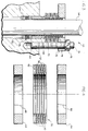
- Figures 1 and 2 illustrate a sliding stem valve incorporating the invention
- Figures 3 and 4 illustrate a rotating shaft valve incorporating the invention.
- a fluid valve 10 of the sliding stem valve type having a valve body with a valve bonnet 12 through which extends an operating valve member illustrated as sliding stem 14.
- Packing nuts 16 are threadably mounted on packing studs 18 so as to adjust the loading on the packing within the bonnet and around the valve stem.
- the improved packing includes a pair of flexible graphite rings 22 which are conventional packing rings of die formed ribbon flexible graphite.
- the flexible graphite rings 22 are relatively soft material each of which readily acts to seal the valve stem.
- each of the graphite composite packing end rings 24 are commonly available items from Argo Packing Company of Oakmont, Pennsylvania and are manufactured in accordance with the aforementioned Union Carbide Corporation patent, U.S. Patent No. 4,826,181.
- Composite rings 24 are formed of somewhat harder material than flexible graphite rings 22 so as to act as anti-extrusion members to help prevent transfer of the somewhat softer flexible graphite material on stem 14. Since the composite rings 24 are slightly harder than flexible graphite rings 22, rings 24 tend to wipe the sliding stem valve 14 during operation thereof so as to aid in the prevention of transfer of flexible graphite material to the stem.
- a conventional carbon bushing 26 is located at each opposite end of the packing. Since carbon bushings 26 are somewhat harder than composite end rings 24, they act as anti-extrusion rings and also aid in maintaining valve stem 14 centered in the packing box to prevent deformation and destruction of the softer packing material in composite rings 24 and flexible graphite rings 22.
- a somewhat larger carbon bushing spacer ring 28 is mounted at one end of the packing indicated at the bottom end illustrated in the drawings adjacent packing box end ring 29 so as to take up the rest of the space within the packing box and to provide support for the sliding stem 14.
- a plurality of PTFE discs each about 0.015 inch (0.381 mm) are provided. In the preferred embodiment of the invention five PTFE discs are used. As illustrated, a respective PTFE disc 30 is inserted between each of the packing rings 22 and between graphite composite packing rings 24 and bushing 26 at the top of the packing system.
- the PTFE discs are intended to partially extrude inward against the stem 14 so that the PTFE material will lubricate the sliding of the stem through the packing.
- the PTFE discs serve as a lubricant in the packing system as well as a sealing member to aid the graphite packing rings in their sealing function.
- a live load packing system is provided so that the packing members are maintained at a stress level that is high enough to readily cause the PTFE discs to extrude.
- the live load packing includes a packing follower 32 having a follower base 34 at one end, a follower guide sleeve 36 at the other end, and a follower flange 38 therebetween.
- Follower 32 includes a liner 40 formed of carbon filled PTFE or other suitable material which may be bonded to the inside surface of the packing follower as disclosed in a copending application, S/N 07/594,843 assigned to the same assignee as herein.
- a series of Belleville disc springs 42 is slidably mounted on follower guide sleeve 36 with one end of the disc springs in contact with flange 38.
- Packing flange 44 has suitable apertures through which the packing studs may be passed and includes a central aperture 46 to allow passage of valve stem 14.
- One end of Belleville disc springs 42 lies in contact with packing flange 44.
- the packing nuts 16 on studs 18 surrounding valve stem 14 are tightened so that packing flange 44 transmits the packing stud and nut load to the Belleville disc springs 42.
- the Belleville springs 42 in turn become compressed with continued tightening of nuts 16 as shown in Figure 1 so as to maintain a spring load on packing rings 22, 24, 26, 28 and 30 through packing follower 32.
- an O-ring (not shown) may be used on follower guide sleeve 36 to maintain the Belleville disc springs in position prior to assembly on stem 14.
- valve 10 reduces fluid leakage to virtually zero so that the valve of this invention can meet the most stringent fluid leakage requirements presently in existence.
- PTFE discs 30 provide the desired significant sealing and lubricating qualities of PTFE material and yet because the discs are of a small volume percentage with respect to the total packing volume, catastrophic failures under high temperature fire conditions is avoided.
- the present invention therefore provides the desired use of PTFE material in an improved packing without incurring the usual detrimental effects of PTFE material at higher operating temperatures. It is understood that in accordance with standard valve practice, zinc discs can be utilized in the packing as sacrificial material to minimize stem corrosion.
- valve body includes a valve bonnet 52 through which rotates an operating valve member illustrated as rotating shaft 54.
- improved graphite packing which includes a laminated ring 56.
- Laminated ring 56 is preferably formed in a die forming operation wherein the alternating flexible graphite and PTFE sheets are suitably bonded with heat and pressure in a standard laminating operation and die formed in order to die cut ring 56 in the illustrated crown shaped cross-section.
- lowermost flexible graphite ring 58 is formed with a cross-sectional crown radius 62.
- the crown radius decreases in the upper layers of the ring so that the top most layer is substantially flat or has a very slight crown radius compared to the lowermost ring crown radius. It is preferred to form ring 56 with the crown shaped cross-section so as to enable axial loading of the packing to flatten the packing ring and allow it to exert a radial force on shaft 54 and on the packing box bore.
- Each of the PTFE thin disc rings 60 are formed of 0.005 inch (0.127 mm) thick PTFE sheet material.
- Each of the flexible graphite rings 58 are formed of 0.030 inch (0.762 mm) thick flexible graphite sheet material.
- the PTFE disc rings are intended to controllably, partially extrude inward against shaft 54 so that the PTFE material will lubricate the shaft as it rotates through the packing.
- the PTFE disc rings serve as a lubricant in the packing system as well as a sealing member to aid the flexible graphite rings in their sealing function.
- Carbon rings 64 which act as anti-extrusion rings and also aid in maintaining rotary shaft 54 centered in the packing box.
- Carbon rings 64 are of the zero clearance anti-extrusion type referred to in co-pending application serial no. 07/596,225, assigned to the same assignee as herein.
- carbon bushings 64 are split and formed with an inner diameter slightly less than the diameter of rotating shaft 54 and an outer diameter slightly less than the packing bore.
- Bushings 64 are split with a single fracture 66 which enables the bushings to be inserted onto the operating member with a zero clearance or interference fit while still permitting axial movement on the operating member and thereby transmitting gland loading to the packing.
- a live load packing system is provided so that the packing members are maintained at a stress level that is high enough to readily cause the PTFE disc rings to controllably extrude.
- the live load packing includes a packing follower 68 which includes a liner formed of carbon filled PTFE which may be bonded to the inside surface of the packing follower.
- a series of Belleville disc springs 70 is slidably mounted on the follower guide sleeve with one end of the disc springs in contact with a packing follower flange as noted in Figure 3.
- Packing flange 72 has suitable apertures through which the packing studs, such as packing stud 74, may be passed. Packing flange 72 further includes a central aperture to allow passage of rotating shaft 54. One end of the Belleville disc springs lies in contact with packing flange 72.
- packing nuts 76 are tightened on studs 74 so that packing flange 72 transmits the packing stud and nut load to the Belleville disc springs 70.
- the Belleville springs in turn become compressed with continued tightening of the nuts so as to maintain a spring load on packing rings 56 and 64 through packing follower 68.
- O-ring 78 is provided on the follower guide sleeve so as to maintain the Belleville disc springs in position prior to assembly on shaft 54.
- a conventional metal packing box ring 80 is mounted within the packing bore to form the bottom of the packing box.
- PEEK rings can be used in place of the carbon rings 64.
- graphite composite end rings such as rings 24 described previously may be used between the laminated ring 56 and the upper and lower rings 64.
- the same laminated ring 56 configuration could also be used without the crown shape cross-section by controlling the fit of ring 56 with shaft 54 and with the packing box bore.
- the axial load required from the packing follower in order to achieve this desired result may be greater than is required with the crown shaped cross-section configuration of ring 56.
- bushings 26 shown in Figure 1 may be formed with a high compressive strength linear aromatic polymer such as polyetheretherketone (PEEK).
Landscapes
- Engineering & Computer Science (AREA)
- General Engineering & Computer Science (AREA)
- Mechanical Engineering (AREA)
- Sealing Devices (AREA)
- Details Of Valves (AREA)
- Sealing Material Composition (AREA)
- Gasket Seals (AREA)
- Diaphragms For Electromechanical Transducers (AREA)
- Manufacture Of Macromolecular Shaped Articles (AREA)
- Heating, Cooling, Or Curing Plastics Or The Like In General (AREA)
Applications Claiming Priority (5)
| Application Number | Priority Date | Filing Date | Title |
|---|---|---|---|
| US63209790A | 1990-12-21 | 1990-12-21 | |
| US632097 | 1990-12-21 | ||
| US79143191A | 1991-11-13 | 1991-11-13 | |
| US791431 | 1991-11-13 | ||
| EP91870215A EP0494064B1 (de) | 1990-12-21 | 1991-12-20 | Graphitdichtung |
Related Parent Applications (2)
| Application Number | Title | Priority Date | Filing Date |
|---|---|---|---|
| EP91870215A Division EP0494064B1 (de) | 1990-12-21 | 1991-12-20 | Graphitdichtung |
| EP91870215.0 Division | 1991-12-20 |
Publications (3)
| Publication Number | Publication Date |
|---|---|
| EP0672851A2 true EP0672851A2 (de) | 1995-09-20 |
| EP0672851A3 EP0672851A3 (de) | 1995-12-06 |
| EP0672851B1 EP0672851B1 (de) | 1999-08-11 |
Family
ID=27091545
Family Applications (2)
| Application Number | Title | Priority Date | Filing Date |
|---|---|---|---|
| EP95109148A Expired - Lifetime EP0672851B1 (de) | 1990-12-21 | 1991-12-20 | Graphitdichtung |
| EP91870215A Expired - Lifetime EP0494064B1 (de) | 1990-12-21 | 1991-12-20 | Graphitdichtung |
Family Applications After (1)
| Application Number | Title | Priority Date | Filing Date |
|---|---|---|---|
| EP91870215A Expired - Lifetime EP0494064B1 (de) | 1990-12-21 | 1991-12-20 | Graphitdichtung |
Country Status (8)
| Country | Link |
|---|---|
| US (2) | US5299812A (de) |
| EP (2) | EP0672851B1 (de) |
| JP (1) | JP3229890B2 (de) |
| KR (1) | KR950005880B1 (de) |
| AT (2) | ATE183295T1 (de) |
| AU (2) | AU663690B2 (de) |
| DE (2) | DE69117484T2 (de) |
| FI (1) | FI916072A7 (de) |
Cited By (4)
| Publication number | Priority date | Publication date | Assignee | Title |
|---|---|---|---|---|
| DE19828789A1 (de) * | 1998-06-27 | 1999-12-30 | Sgl Technik Gmbh | Packungsgarn aus Graphit- und Plastikfolie |
| US6777086B2 (en) | 2001-08-31 | 2004-08-17 | Julian Norley | Laminates prepared from impregnated flexible graphite sheets |
| WO2006101600A1 (en) * | 2005-03-18 | 2006-09-28 | Fisher Controls International Llc | Split packing follower for use with valves |
| DE202019001783U1 (de) | 2019-04-20 | 2019-05-22 | HAFF-Dichtungen GmbH | Dichtungsartikel |
Families Citing this family (45)
| Publication number | Priority date | Publication date | Assignee | Title |
|---|---|---|---|---|
| ATE183295T1 (de) * | 1990-12-21 | 1999-08-15 | Fisher Controls Int | Graphitdichtung |
| US5503406A (en) * | 1993-11-26 | 1996-04-02 | Neles-Jamesbury | Assembly for live loading or valve packings |
| US5593166A (en) * | 1994-03-02 | 1997-01-14 | Fisher Controls International, Inc. | Low friction packing |
| US5577709A (en) * | 1995-10-17 | 1996-11-26 | Henry Valve Company | Stem seal configuration for ball valves |
| US5791629A (en) * | 1996-10-31 | 1998-08-11 | Fisher Controls International, Inc. | Bushing-less stem guided control valve |
| RU2197661C1 (ru) * | 2002-03-18 | 2003-01-27 | Андреев Александр Павлович | Сальниковое уплотнение |
| RU2197660C1 (ru) * | 2002-03-18 | 2003-01-27 | Андреев Александр Павлович | Сальниковое уплотнение |
| RU2197659C1 (ru) * | 2002-03-18 | 2003-01-27 | Андреев Александр Павлович | Устройство уплотнения подвижных и неподвижных соединений (варианты) |
| US20050082766A1 (en) * | 2003-10-15 | 2005-04-21 | Fisher Controls International | Low adhesion additive |
| DE20316372U1 (de) * | 2003-10-23 | 2003-12-18 | Fey Lamellenringe Gmbh & Co. Kg | Flanschverbindung |
| US20060076526A1 (en) * | 2004-10-13 | 2006-04-13 | Varco I/P, Inc. | Anodic Protective Seal in a Blowout Preventer |
| US7963502B2 (en) * | 2006-08-25 | 2011-06-21 | Fisher Controls International Llc | Low friction live-loaded packing |
| US7559364B2 (en) * | 2006-09-14 | 2009-07-14 | Gerald Bullard | Bridge plug and setting tool |
| US7757756B2 (en) * | 2006-09-14 | 2010-07-20 | Gerald Bullard | Bridge plug and setting tool |
| US7854239B2 (en) * | 2008-03-03 | 2010-12-21 | Fisher Controls International Llc | High temperature valve |
| KR100902259B1 (ko) * | 2009-01-16 | 2009-06-11 | 김방현 | 슬라이딩 디스크 밸브 |
| US8613423B2 (en) | 2009-07-13 | 2013-12-24 | Fisher Controls International Llc | Methods and apparatus to load a valve packing |
| US8632053B2 (en) | 2010-05-11 | 2014-01-21 | Fisher Controls International, Llc | Movable valve apparatus having conditioned lubricating surfaces |
| CN102401186A (zh) * | 2011-07-14 | 2012-04-04 | 世林(漯河)冶金设备有限公司 | 一种高炉三偏心切断蝶阀填料预紧结构 |
| DE102011055740A1 (de) | 2011-11-25 | 2013-05-29 | Kempchen Dichtungstechnik Gmbh | Dichtpackungsring sowie Dichtpackungssatz mit einer Vielzahl von Dichtpackungsringen |
| US9188242B2 (en) * | 2012-05-08 | 2015-11-17 | Control Components, Inc. | Low diffusivity barrier fluid packing system |
| US8857792B2 (en) | 2012-05-14 | 2014-10-14 | Fisher Controls International Llc | Seal ring assemblies for use with rotary valves |
| US10001214B2 (en) | 2013-11-26 | 2018-06-19 | Baker Hughes, A Ge Company, Llc | Seal arrangement and method of sealing |
| US9863552B2 (en) | 2014-06-24 | 2018-01-09 | Jdv Control Valves Co., Ltd. | Fluid valve and a single shaft-sealing module thereof |
| US10330209B2 (en) | 2017-01-26 | 2019-06-25 | Fresenius Medical Care Holdings, Inc. | Check valve and method of forming a check valve |
| GB2586274A (en) * | 2019-08-16 | 2021-02-17 | Oliver Twinsafe Valves Ltd | Valve with sealing system |
| US11421679B1 (en) | 2020-06-30 | 2022-08-23 | Vulcan Industrial Holdings, LLC | Packing assembly with threaded sleeve for interaction with an installation tool |
| US12049889B2 (en) | 2020-06-30 | 2024-07-30 | Vulcan Industrial Holdings, LLC | Packing bore wear sleeve retainer system |
| US12366245B1 (en) | 2020-08-27 | 2025-07-22 | Vulcan Industrial Holdings, LLC | Connecting rod assembly for reciprocating pump |
| US12055221B2 (en) | 2021-01-14 | 2024-08-06 | Vulcan Industrial Holdings, LLC | Dual ring stuffing box |
| US12292120B1 (en) | 2021-02-23 | 2025-05-06 | Vulcan Industrial Holdings, LLC | System and method for valve assembly |
| US11846356B1 (en) | 2021-08-18 | 2023-12-19 | Vulcan Industrial Holdings, LLC | Self-locking plug |
| US12510164B1 (en) | 2021-08-18 | 2025-12-30 | Vulcan Industrial Holdings, LLC | Sleeved fluid end |
| US12140240B1 (en) | 2022-01-19 | 2024-11-12 | Vulcan Industrial Holdings, LLC | Gradient material structures and methods of forming the same |
| JP7593346B2 (ja) * | 2022-01-28 | 2024-12-03 | Jfeスチール株式会社 | 軸封装置及びゲート弁 |
| US12297922B1 (en) | 2022-03-04 | 2025-05-13 | Vulcan Industrial Holdings, LLC | Valve seat with embedded structure and related methods |
| US11434900B1 (en) | 2022-04-25 | 2022-09-06 | Vulcan Industrial Holdings, LLC | Spring controlling valve |
| USD1113987S1 (en) | 2022-05-20 | 2026-02-17 | Vulcan Industrial Holdings, LLC | Header ring for a pumping system |
| US11852248B2 (en) | 2022-05-24 | 2023-12-26 | Fisher Controls International Llc | Packing system and diagnostic method for a packing system of a valve assembly |
| USD1061623S1 (en) | 2022-08-03 | 2025-02-11 | Vulcan Industrial Holdings, LLC | Fluid end for a pumping system |
| US12650171B2 (en) | 2023-05-08 | 2026-06-09 | Vulcan Industrial Holdings, LLC | Systems, assemblies, apparatuses, and methods providing enhanced fluid seal for high-power pumps |
| US12292121B2 (en) | 2023-08-10 | 2025-05-06 | Vulcan Industrial Holdings, LLC | Valve member including cavity, and related assemblies, systems, and methods |
| US20250146598A1 (en) * | 2023-11-03 | 2025-05-08 | EGC Operating Company LLC (dba EGC Enterprises Inc.) | Valve packing ring set |
| US20260063222A1 (en) * | 2024-08-27 | 2026-03-05 | Dresser, Llc | Preventing wear or damage to a valve stem on a valve |
| DE102024126168A1 (de) * | 2024-09-11 | 2026-03-12 | Samson Aktiengesellschaft | Dichtungsanordnung für ein Hubventil und Hubventil |
Citations (1)
| Publication number | Priority date | Publication date | Assignee | Title |
|---|---|---|---|---|
| US4826181A (en) | 1988-02-09 | 1989-05-02 | Union Carbide Corporation | Seal utilizing composites of flexible graphite particles and amorphous carbon |
Family Cites Families (25)
| Publication number | Priority date | Publication date | Assignee | Title |
|---|---|---|---|---|
| US1417877A (en) * | 1919-04-16 | 1922-05-30 | Wright Arthur | Rod packing |
| US1594517A (en) * | 1925-01-09 | 1926-08-03 | Dufty Noel Evelyn | Guide for valves of internal-combustion engines |
| US2567479A (en) * | 1947-09-08 | 1951-09-11 | Phillips Petroleum Co | Polish rod stuffing box |
| US3316940A (en) * | 1964-06-29 | 1967-05-02 | Gratzmuller Jean Louis | Sliding seal assemblies |
| US4363463A (en) * | 1977-06-08 | 1982-12-14 | Robertshaw Controls Company | Plunger seal assembly and method of making the same |
| ZA796406B (en) * | 1978-11-28 | 1980-11-26 | Fletcher Sutcliffe Wild Ltd | Hydraulic pump |
| DE2942598A1 (de) * | 1979-10-22 | 1981-04-30 | Feodor Burgmann Dichtungswerk Gmbh & Co, 8190 Wolfratshausen | Dichtungsring |
| US4438957A (en) * | 1980-04-01 | 1984-03-27 | Fmc Corporation | Constant motion swivel joint |
| US4379557A (en) * | 1981-03-05 | 1983-04-12 | Acf Industries, Incorporated | Valve stem packing structure |
| JPS57173665A (en) * | 1981-04-17 | 1982-10-26 | Toshiba Corp | Gland seal |
| US4451047A (en) * | 1981-07-31 | 1984-05-29 | Smith International, Inc. | Seal |
| US4408769A (en) * | 1982-09-21 | 1983-10-11 | Jude Engineering, Inc. | Stuffing box with outer flexible tube to allow shaft gyratory movements |
| US4394023A (en) * | 1982-09-29 | 1983-07-19 | Daniel Industries Inc. | High temperature valve stem packing with coiled graphite seal rings |
| US4630636A (en) * | 1983-11-16 | 1986-12-23 | Baker Cac | Actuator with nonelastomeric seal |
| US4577872A (en) * | 1984-08-02 | 1986-03-25 | Rockwell International Corporation | Valve stem seal with multiple ring means |
| US4527806A (en) * | 1984-12-12 | 1985-07-09 | Fmc Corporation | Valve stem packing |
| DE3534135A1 (de) * | 1985-09-25 | 1987-04-02 | Hp & Hp Chemie Stellglieder | Abdichtungseinrichtung an einer kolben-zylinderanordnung, insbesondere zur abdichtung des ventilkegels an ventilen mit druckausgleich |
| US4720113A (en) * | 1985-11-14 | 1988-01-19 | Seals Eastern Inc. | Multilayer, multihardness seal |
| US4635945A (en) * | 1986-03-21 | 1987-01-13 | Microdot Inc. | Anti-extrusion seal with primary and secondary complementary elements |
| DE3721967C1 (de) * | 1987-07-03 | 1987-12-03 | Kempchen & Co Gmbh | Stopfbuchsdichtung |
| US4886241A (en) * | 1987-09-16 | 1989-12-12 | Fisher Controls International, Inc. | Valve stem packing containment for high pressure, high temperature |
| US4811959A (en) * | 1987-11-27 | 1989-03-14 | Otis Engineering Corporation | Seal assembly for well locking mandrel |
| US4961991A (en) * | 1990-01-29 | 1990-10-09 | Ucar Carbon Technology Corporation | Flexible graphite laminate |
| ATE183295T1 (de) * | 1990-12-21 | 1999-08-15 | Fisher Controls Int | Graphitdichtung |
| US5198063A (en) * | 1991-06-03 | 1993-03-30 | Ucar Carbon Technology Corporation | Method and assembly for reinforcing flexible graphite and article |
-
1991
- 1991-12-20 AT AT95109148T patent/ATE183295T1/de active
- 1991-12-20 DE DE69117484T patent/DE69117484T2/de not_active Expired - Lifetime
- 1991-12-20 FI FI916072A patent/FI916072A7/fi not_active Application Discontinuation
- 1991-12-20 AU AU89913/91A patent/AU663690B2/en not_active Ceased
- 1991-12-20 AT AT91870215T patent/ATE134753T1/de not_active IP Right Cessation
- 1991-12-20 KR KR1019910023628A patent/KR950005880B1/ko not_active Expired - Fee Related
- 1991-12-20 EP EP95109148A patent/EP0672851B1/de not_active Expired - Lifetime
- 1991-12-20 JP JP33884691A patent/JP3229890B2/ja not_active Expired - Fee Related
- 1991-12-20 EP EP91870215A patent/EP0494064B1/de not_active Expired - Lifetime
- 1991-12-20 DE DE69131526T patent/DE69131526T2/de not_active Expired - Lifetime
-
1992
- 1992-12-15 US US07/991,086 patent/US5299812A/en not_active Expired - Lifetime
-
1996
- 1996-01-05 US US08/583,270 patent/US5542681A/en not_active Expired - Lifetime
- 1996-01-12 AU AU40940/96A patent/AU4094096A/en not_active Abandoned
Patent Citations (1)
| Publication number | Priority date | Publication date | Assignee | Title |
|---|---|---|---|---|
| US4826181A (en) | 1988-02-09 | 1989-05-02 | Union Carbide Corporation | Seal utilizing composites of flexible graphite particles and amorphous carbon |
Cited By (7)
| Publication number | Priority date | Publication date | Assignee | Title |
|---|---|---|---|---|
| DE19828789A1 (de) * | 1998-06-27 | 1999-12-30 | Sgl Technik Gmbh | Packungsgarn aus Graphit- und Plastikfolie |
| US6270083B1 (en) | 1998-06-27 | 2001-08-07 | Sgl Technik Gmbh | Packing yarn made of graphite foil and plastic foil and method of manufacturing a packing yarn |
| US6777086B2 (en) | 2001-08-31 | 2004-08-17 | Julian Norley | Laminates prepared from impregnated flexible graphite sheets |
| WO2006101600A1 (en) * | 2005-03-18 | 2006-09-28 | Fisher Controls International Llc | Split packing follower for use with valves |
| US7303179B2 (en) | 2005-03-18 | 2007-12-04 | Fisher Controls International Llc | Split packing follower for use with valves |
| RU2433327C2 (ru) * | 2005-03-18 | 2011-11-10 | Фишер Контролз Интернешнел Ллс | Разъемная крышка сальника для использования с клапанами |
| DE202019001783U1 (de) | 2019-04-20 | 2019-05-22 | HAFF-Dichtungen GmbH | Dichtungsartikel |
Also Published As
| Publication number | Publication date |
|---|---|
| FI916072A7 (fi) | 1992-06-22 |
| JPH04285366A (ja) | 1992-10-09 |
| KR920012798A (ko) | 1992-07-27 |
| US5542681A (en) | 1996-08-06 |
| EP0672851A3 (de) | 1995-12-06 |
| AU4094096A (en) | 1996-04-18 |
| EP0672851B1 (de) | 1999-08-11 |
| EP0494064B1 (de) | 1996-02-28 |
| ATE134753T1 (de) | 1996-03-15 |
| ATE183295T1 (de) | 1999-08-15 |
| DE69131526T2 (de) | 2000-05-04 |
| DE69117484D1 (de) | 1996-04-04 |
| AU663690B2 (en) | 1995-10-19 |
| FI916072A0 (fi) | 1991-12-20 |
| US5299812A (en) | 1994-04-05 |
| AU8991391A (en) | 1992-06-25 |
| KR950005880B1 (ko) | 1995-06-02 |
| JP3229890B2 (ja) | 2001-11-19 |
| DE69117484T2 (de) | 1996-08-22 |
| EP0494064A1 (de) | 1992-07-08 |
| DE69131526D1 (de) | 1999-09-16 |
Similar Documents
| Publication | Publication Date | Title |
|---|---|---|
| US5542681A (en) | Graphite packing | |
| AU679347B2 (en) | Low friction packing | |
| US4451047A (en) | Seal | |
| EP0483097B1 (de) | Spielfreie Stützringe für die Beschränkung von PTFE-Packungen | |
| EP0046774B1 (de) | Stopfbüchsen-dichtungssystem | |
| US5129625A (en) | Live load packing system | |
| EP0483096B1 (de) | Beschränkung der Packung einer gefederten Stoffbüchse zur Verhinderung des Extrusionsverschleisses | |
| US3275331A (en) | Seal and method of manufacture | |
| EP0060238A1 (de) | Ventilspindelabdichtung | |
| GB2103310A (en) | Seal | |
| US11746925B2 (en) | Valve packing ring set | |
| JPS6215794B2 (de) | ||
| CA2058256C (en) | Graphite packing | |
| CA2184620C (en) | Low friction packing | |
| CA2058265C (en) | Graphite packing with ptfe discs | |
| US3387850A (en) | Method of manufacturing a seal | |
| RU2065109C1 (ru) | Уплотнительный узел штока запорно-регулирующей арматуры | |
| US10955054B2 (en) | Mechanical seal arrangement and well bore conveyor device | |
| US20200362968A1 (en) | Accordion Style Valve Bonnet and Stem Seal | |
| US20250146598A1 (en) | Valve packing ring set | |
| US20200408306A1 (en) | Fugitive emissions packing set | |
| SU754153A1 (ru) | Дублирующее сальниковое устройство |
Legal Events
| Date | Code | Title | Description |
|---|---|---|---|
| PUAI | Public reference made under article 153(3) epc to a published international application that has entered the european phase |
Free format text: ORIGINAL CODE: 0009012 |
|
| AC | Divisional application: reference to earlier application |
Ref document number: 494064 Country of ref document: EP |
|
| AK | Designated contracting states |
Kind code of ref document: A2 Designated state(s): AT BE DE FR GB IT NL |
|
| PUAL | Search report despatched |
Free format text: ORIGINAL CODE: 0009013 |
|
| AK | Designated contracting states |
Kind code of ref document: A3 Designated state(s): AT BE DE FR GB IT NL |
|
| 17P | Request for examination filed |
Effective date: 19960529 |
|
| 17Q | First examination report despatched |
Effective date: 19971023 |
|
| GRAG | Despatch of communication of intention to grant |
Free format text: ORIGINAL CODE: EPIDOS AGRA |
|
| GRAG | Despatch of communication of intention to grant |
Free format text: ORIGINAL CODE: EPIDOS AGRA |
|
| GRAH | Despatch of communication of intention to grant a patent |
Free format text: ORIGINAL CODE: EPIDOS IGRA |
|
| GRAH | Despatch of communication of intention to grant a patent |
Free format text: ORIGINAL CODE: EPIDOS IGRA |
|
| GRAA | (expected) grant |
Free format text: ORIGINAL CODE: 0009210 |
|
| AC | Divisional application: reference to earlier application |
Ref document number: 494064 Country of ref document: EP |
|
| AK | Designated contracting states |
Kind code of ref document: B1 Designated state(s): AT BE DE FR GB IT NL |
|
| PG25 | Lapsed in a contracting state [announced via postgrant information from national office to epo] |
Ref country code: NL Free format text: LAPSE BECAUSE OF FAILURE TO SUBMIT A TRANSLATION OF THE DESCRIPTION OR TO PAY THE FEE WITHIN THE PRESCRIBED TIME-LIMIT Effective date: 19990811 |
|
| REF | Corresponds to: |
Ref document number: 183295 Country of ref document: AT Date of ref document: 19990815 Kind code of ref document: T |
|
| REF | Corresponds to: |
Ref document number: 69131526 Country of ref document: DE Date of ref document: 19990916 |
|
| ITF | It: translation for a ep patent filed | ||
| PGFP | Annual fee paid to national office [announced via postgrant information from national office to epo] |
Ref country code: AT Payment date: 19991209 Year of fee payment: 9 |
|
| ET | Fr: translation filed | ||
| NLV1 | Nl: lapsed or annulled due to failure to fulfill the requirements of art. 29p and 29m of the patents act | ||
| PGFP | Annual fee paid to national office [announced via postgrant information from national office to epo] |
Ref country code: BE Payment date: 20000217 Year of fee payment: 9 |
|
| PLBE | No opposition filed within time limit |
Free format text: ORIGINAL CODE: 0009261 |
|
| STAA | Information on the status of an ep patent application or granted ep patent |
Free format text: STATUS: NO OPPOSITION FILED WITHIN TIME LIMIT |
|
| 26N | No opposition filed | ||
| PG25 | Lapsed in a contracting state [announced via postgrant information from national office to epo] |
Ref country code: AT Free format text: LAPSE BECAUSE OF NON-PAYMENT OF DUE FEES Effective date: 20001220 |
|
| PG25 | Lapsed in a contracting state [announced via postgrant information from national office to epo] |
Ref country code: BE Free format text: LAPSE BECAUSE OF NON-PAYMENT OF DUE FEES Effective date: 20001231 |
|
| BERE | Be: lapsed |
Owner name: FISHER CONTROLS INTERNATIONAL INC. Effective date: 20001231 |
|
| REG | Reference to a national code |
Ref country code: GB Ref legal event code: IF02 |
|
| REG | Reference to a national code |
Ref country code: FR Ref legal event code: CD Ref country code: FR Ref legal event code: CA |
|
| PG25 | Lapsed in a contracting state [announced via postgrant information from national office to epo] |
Ref country code: IT Free format text: LAPSE BECAUSE OF NON-PAYMENT OF DUE FEES Effective date: 20051220 |
|
| PGFP | Annual fee paid to national office [announced via postgrant information from national office to epo] |
Ref country code: FR Payment date: 20101224 Year of fee payment: 20 |
|
| PGFP | Annual fee paid to national office [announced via postgrant information from national office to epo] |
Ref country code: GB Payment date: 20101215 Year of fee payment: 20 |
|
| PGFP | Annual fee paid to national office [announced via postgrant information from national office to epo] |
Ref country code: DE Payment date: 20101215 Year of fee payment: 20 |
|
| REG | Reference to a national code |
Ref country code: DE Ref legal event code: R071 Ref document number: 69131526 Country of ref document: DE |
|
| REG | Reference to a national code |
Ref country code: DE Ref legal event code: R071 Ref document number: 69131526 Country of ref document: DE |
|
| REG | Reference to a national code |
Ref country code: GB Ref legal event code: PE20 Expiry date: 20111219 |
|
| PG25 | Lapsed in a contracting state [announced via postgrant information from national office to epo] |
Ref country code: GB Free format text: LAPSE BECAUSE OF EXPIRATION OF PROTECTION Effective date: 20111219 |
|
| PG25 | Lapsed in a contracting state [announced via postgrant information from national office to epo] |
Ref country code: DE Free format text: LAPSE BECAUSE OF EXPIRATION OF PROTECTION Effective date: 20111221 |