EP0672913A2 - Magnetfeldsensor - Google Patents
Magnetfeldsensor Download PDFInfo
- Publication number
- EP0672913A2 EP0672913A2 EP95301609A EP95301609A EP0672913A2 EP 0672913 A2 EP0672913 A2 EP 0672913A2 EP 95301609 A EP95301609 A EP 95301609A EP 95301609 A EP95301609 A EP 95301609A EP 0672913 A2 EP0672913 A2 EP 0672913A2
- Authority
- EP
- European Patent Office
- Prior art keywords
- magnetic field
- sensor
- bridge
- resonant frequency
- light
- Prior art date
- Legal status (The legal status is an assumption and is not a legal conclusion. Google has not performed a legal analysis and makes no representation as to the accuracy of the status listed.)
- Withdrawn
Links
Images

Classifications
-
- G—PHYSICS
- G01—MEASURING; TESTING
- G01R—MEASURING ELECTRIC VARIABLES; MEASURING MAGNETIC VARIABLES
- G01R33/00—Arrangements or instruments for measuring magnetic variables
- G01R33/02—Measuring direction or magnitude of magnetic fields or magnetic flux
- G01R33/032—Measuring direction or magnitude of magnetic fields or magnetic flux using magneto-optic devices, e.g. Faraday or Cotton-Mouton effect
- G01R33/0327—Measuring direction or magnitude of magnetic fields or magnetic flux using magneto-optic devices, e.g. Faraday or Cotton-Mouton effect with application of magnetostriction
Definitions
- the present invention relates to a magnetic field sensor.
- Magnetostriction whereby the dimensions of a material change with changes in magnetic field strength, can be utilised to form a magnetic field sensor.
- DE-A-4 028 366 describes a sensor in which a foil of magnetostrictive material forms one electrode of a capacitor. Changes in the dimensions of the magnetostrictive foil with changing magnetic field alters the separation between the plates of the capacitor, thereby causing the capacitance to vary with magnetic field.
- a “Delta E” effect is observed in certain magnetic materials, such as amorphous iron alloys, in which the elastic modulus of the material is a function of magnetic field.
- a magnetic field sensor comprising a beam and changing means responsive to a magnetic field for changing a measurable property of the beam.
- the measurable property of the beam is the resonant frequency of the beam.
- the beam is made of silicon.
- the silicon is monocrystalline silicon.
- the beam may be made of a metal exhibiting magnetostriction, such as nickel, or a combination of a magnetostrictive metal and silicon, or of a magnetostrictive coating on any suitable support material.
- a magnetostrictive metal suitable for the sensor is an iron, cobalt, silver multilayer film, for instance of the type disclosed by T.A. Lafford, M.R.J. Gibbs, and C. Shearwood in "Magnetic, magnetostrictive and structural properties of iron-cobalt/silver multilayers", Journal of Magnetism and Magnetic Materials 132 (1994) 89-94.
- the beam may be driven to vibrate optically, i.e. by the effect of local thermal expansion on one side of the beam, or by electrostatic, piezoelectric or any other suitable excitation.
- the beam is driven at a frequency near or at the resonant frequency of the beam.
- the driving frequency may be swept across a predetermined band of frequencies and the motion of the beam monitored to determine the resonant frequency of the beam.
- the beam may be arranged to undergo auto-oscillation, whereby the beam resonates in response to illumination from a substantially non-varying light.
- Auto-oscillation may be achieved by illuminating the beam at an angle to the normal of the surface of the beam such that the intensity of the light impinging on the beam is a function of the position of the beam or the illuminated part thereof.
- the motion of the beam may be sensed optically.
- piezoelectric, piezoresistive, or capacitive detection may be used.
- Optical detection has the advantage of great immunity to electrical noise.
- the beam may be supported at either end thereof.
- the beam may be provided as a cantilever.
- the measurable property of the beam may be the deflection of the beam.
- the beam may be arranged to act as a movable reflector within an interferometer.
- the interferometer may be illuminated with substantially monochromatic light, so that position may be determined by counting cyclic variations in intensity with changing position.
- the interferometer may be illuminated by polychromatic light so that the colour of light reflected from the interferometer is indicative of the position of the beam.
- a magnetic field sensor comprising a beam and a stressing member of magnetostrictive material arranged such that the stressing member exerts a force which is a function of magnetic field on the beam thereby altering the resonant frequency of the beam in response to changes in the magnetic field.
- the stressing member may be applied to a surface of the beam.
- the stressing member may be a layer of nickel deposited on one side of the beam.
- the nickel may be deposited by sputtering.
- the stressing member may be arranged to stress the body of the sensor and thereby exert a force on the beam.
- a magnetic field sensor comprising a beam having a member of material which has an elastic modulus which is a function of magnetic field arranged such that the elastic modulus of the beam is a function of magnetic field thereby altering the resonant frequency of the beam in response to changes in the magnetic field.
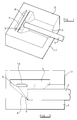
- the magnetic field sensor shown in Figure 1 comprises a body 1 of monocrystalline silicon.
- a groove 2 is etched into a surface 3 of the block so as to define a passage for receiving and securing an optical fibre 4.
- a reflector 6 is etched into a side wall of a well 5 formed within the body 1. The reflector 6 is arranged transversely to the axis of the groove 2 and angled at 45 degrees thereto so as reflect light from the optical fibre 4 in a direction normal to the surface 3.
- a bridge 8 formed above the reflector 6 is coated with a layer 10 of nickel.
- the bridge 8 is typically 800 micrometers long by 60 micrometers wide.
- the bridge 8 comprises silicon approximately 1-2 ⁇ m thick with a 0.5 ⁇ m thick layer of nickel deposited thereon, as shown in Figure 2.
- the layer 10 may comprise an iron-cobalt/silver multilayer, as mentioned hereinbefore, deposited on the silicon bridge.
- Nickel exhibits magnetostriction. In the presence of a magnetic field, the length of the layer 10 of nickel tends to alter. The material of the bridge 8 acts to prevent the layer 10 changing in length. This causes the bridge to be stressed by an amount which is a function of the magnetic field at the layer 10.
- the sensor is provided with a cover 12 which is bonded to the body 1 so as to define a region 14 enclosing the bridge 8.
- the region 14 is substantially evacuated so as to reduce damping effects on the bridge due to viscous drag.
- the bridge 8 may be constructed of sputter deposited nickel approximately 0.5 micrometers thick.
- the resonant frequency of the bridge 8 is a function of the stress experienced by the bridge.
- the bridge receives light from the optical fibre and reflects light back to the optical fibre.
- the intensity of the light received by the optical fibre 4 is modulated by the position of the bridge 8.
- the beam may be driven into oscillation by modulating the light incident on the lower surface of the bridge 8. Absorbtion of the light causes local heating and the resulting thermal expansion, and subsequent contraction when the light intensity is reduced, drives the bridge into vibration.
- the driving frequency is set to be substantially coincident with the resonant frequency of the bridge so as to increase the amplitude of vibration.
- the amplitude of the vibration is determined by measuring the intensity of the light reflected back into the optical fibre 4 from the bridge 8 via the reflector 6. By measuring the vibrational amplitude of the bridge with changes in the driving frequency of the modulated light, the resonant frequency of the bridge can be determined and hence the strength of the magnetic field can be determined.
- FIG 3 shows a second embodiment of a magnetic field sensor similar in structure to the first embodiment.
- the bridge 8 is formed as a cantilever having a free end 16. The bridge, as before, is driven optically and its motion is sensed optically.
- the bridge may be provided by a silicon base coated with a layer of magnetostrictive material such as nickel, as in the first embodiment, such that the stress within the silicon and nickel change with magnetic field, thereby changing the resonant frequency of the bridge.
- the sensor exhibits maximum sensitivity when the direction of the magnetic flux is aligned with the longitudinal axis of the bridge 8, whereas minimum sensitivity occurs when the magnetic field is perpendicular to the surface 3.
- the sensor's response is independent of the "polarity" of the magnetic field, that is it is insensitive to a complete reversal of the direction of the magnetic field.
- the bridge may be made of a material exhibiting the delta E effect such that the elastic modulus of the material of the bridge changes with magnetic field.
- the frequency of vibration of a cantilever varies, to a first approximation, with the square root of the elastic modulus of the material of the cantilever.
Landscapes
- Physics & Mathematics (AREA)
- Engineering & Computer Science (AREA)
- Power Engineering (AREA)
- Condensed Matter Physics & Semiconductors (AREA)
- General Physics & Mathematics (AREA)
- Measuring Magnetic Variables (AREA)
Applications Claiming Priority (2)
| Application Number | Priority Date | Filing Date | Title |
|---|---|---|---|
| GB9405265A GB9405265D0 (en) | 1994-03-17 | 1994-03-17 | Magnetic field sensor |
| GB9405265 | 1994-03-17 |
Publications (2)
| Publication Number | Publication Date |
|---|---|
| EP0672913A2 true EP0672913A2 (de) | 1995-09-20 |
| EP0672913A3 EP0672913A3 (de) | 1996-08-14 |
Family
ID=10752042
Family Applications (1)
| Application Number | Title | Priority Date | Filing Date |
|---|---|---|---|
| EP95301609A Withdrawn EP0672913A3 (de) | 1994-03-17 | 1995-03-09 | Magnetfeldsensor. |
Country Status (2)
| Country | Link |
|---|---|
| EP (1) | EP0672913A3 (de) |
| GB (1) | GB9405265D0 (de) |
Cited By (2)
| Publication number | Priority date | Publication date | Assignee | Title |
|---|---|---|---|---|
| DE19612993C2 (de) * | 1996-03-22 | 2003-12-18 | Forschungsverbund Berlin Ev | Verfahren und Vorrichtung zur Erfassung von Magnetfeldänderungen |
| WO2011053363A1 (en) * | 2009-10-29 | 2011-05-05 | General Electric Company | Optical mems device and remote sensing system utilizing the same |
Family Cites Families (7)
| Publication number | Priority date | Publication date | Assignee | Title |
|---|---|---|---|---|
| US4897541A (en) * | 1984-05-18 | 1990-01-30 | Luxtron Corporation | Sensors for detecting electromagnetic parameters utilizing resonating elements |
| EP0174511A1 (de) * | 1984-08-29 | 1986-03-19 | Siemens Aktiengesellschaft | Faseroptischer Stromsensor |
| GB2194054A (en) * | 1986-08-15 | 1988-02-24 | Gen Electric Co Plc | Magnetometer |
| DE3930902C1 (en) * | 1989-09-15 | 1991-03-21 | Fraunhofer-Gesellschaft Zur Foerderung Der Angewandten Forschung Ev, 8000 Muenchen, De | Fibre optic sensor for different physical parameters - has resonant vibrating tongue clamped at one side, with excitation and measurement light wave conductors |
| US5103174A (en) * | 1990-02-26 | 1992-04-07 | The United States Of America As Represented By The Secretary Of The Navy | Magnetic field sensor and device for determining the magnetostriction of a material based on a tunneling tip detector and methods of using same |
| DE59002106D1 (de) * | 1990-03-09 | 1993-09-02 | Landis & Gyr Business Support | Vorrichtung zum messen einer magnetischen induktion. |
| GB9203128D0 (en) * | 1992-02-14 | 1992-04-01 | Lucas Ind Plc | Alignment device for optical fibre |
-
1994
- 1994-03-17 GB GB9405265A patent/GB9405265D0/en active Pending
-
1995
- 1995-03-09 EP EP95301609A patent/EP0672913A3/de not_active Withdrawn
Cited By (2)
| Publication number | Priority date | Publication date | Assignee | Title |
|---|---|---|---|---|
| DE19612993C2 (de) * | 1996-03-22 | 2003-12-18 | Forschungsverbund Berlin Ev | Verfahren und Vorrichtung zur Erfassung von Magnetfeldänderungen |
| WO2011053363A1 (en) * | 2009-10-29 | 2011-05-05 | General Electric Company | Optical mems device and remote sensing system utilizing the same |
Also Published As
| Publication number | Publication date |
|---|---|
| GB9405265D0 (en) | 1994-04-27 |
| EP0672913A3 (de) | 1996-08-14 |
Similar Documents
| Publication | Publication Date | Title |
|---|---|---|
| CA1251057A (en) | Optical sensors for detecting physical parameters | |
| US4897541A (en) | Sensors for detecting electromagnetic parameters utilizing resonating elements | |
| US6246638B1 (en) | Fiber-optic vibration sensor based on frequency modulation of light-excited oscillators | |
| US10101222B2 (en) | Piezoelectric position sensor for piezoelectrically driven resonant micromirrors | |
| US4887032A (en) | Resonant vibrating structure with electrically driven wire coil and vibration sensor | |
| US5728936A (en) | Rotary speed sensor | |
| CN101608944B (zh) | 一种光纤振动传感头及其制作方法 | |
| JP4099393B2 (ja) | 集積されたマイクロメカニカル音叉共振器を備えるタイムベース | |
| JP2010286477A (ja) | ジャイロスコープおよび回転検出方法 | |
| GB2221302A (en) | Coriolis-effect fluid mass flow and density sensor made by a micromachining method | |
| US5105665A (en) | Sensors | |
| US6584857B1 (en) | Optical strain gauge | |
| CN1079822A (zh) | 以扫描法布里-珀罗共振器作为传感部分元件的光学压力传感器 | |
| US4739661A (en) | Fiber-optic accelerometer having cantilevered acceleration-sensitive mass | |
| JPH09243444A (ja) | 光振動センサ | |
| US6487913B2 (en) | Strain gauge with resonant light modulator | |
| Langdon et al. | Photoacoustic oscillator sensors | |
| EP0672913A2 (de) | Magnetfeldsensor | |
| US5705809A (en) | Optical transducer for measuring acceleration or vibration using a curved light reflector | |
| US6959600B2 (en) | Vibratory gyroscope | |
| US4866987A (en) | Optical transducer systems | |
| US5447075A (en) | Self-exciting optical strain gage | |
| CA1334630C (en) | Measuring device | |
| Walsh et al. | Optically activated microresonator sensors | |
| GB2235773A (en) | Indirectly excited resonant element sensor |
Legal Events
| Date | Code | Title | Description |
|---|---|---|---|
| PUAI | Public reference made under article 153(3) epc to a published international application that has entered the european phase |
Free format text: ORIGINAL CODE: 0009012 |
|
| AK | Designated contracting states |
Kind code of ref document: A2 Designated state(s): DE ES FR GB IT |
|
| PUAL | Search report despatched |
Free format text: ORIGINAL CODE: 0009013 |
|
| AK | Designated contracting states |
Kind code of ref document: A3 Designated state(s): DE ES FR GB IT |
|
| STAA | Information on the status of an ep patent application or granted ep patent |
Free format text: STATUS: THE APPLICATION IS DEEMED TO BE WITHDRAWN |
|
| 18D | Application deemed to be withdrawn |
Effective date: 19970215 |