EP0673076A1 - Elément pour batterie métal-air - Google Patents
Elément pour batterie métal-air Download PDFInfo
- Publication number
- EP0673076A1 EP0673076A1 EP19940307391 EP94307391A EP0673076A1 EP 0673076 A1 EP0673076 A1 EP 0673076A1 EP 19940307391 EP19940307391 EP 19940307391 EP 94307391 A EP94307391 A EP 94307391A EP 0673076 A1 EP0673076 A1 EP 0673076A1
- Authority
- EP
- European Patent Office
- Prior art keywords
- cell
- air
- housing
- major
- space
- Prior art date
- Legal status (The legal status is an assumption and is not a legal conclusion. Google has not performed a legal analysis and makes no representation as to the accuracy of the status listed.)
- Ceased
Links
- 239000012530 fluid Substances 0.000 claims description 14
- 239000003792 electrolyte Substances 0.000 claims description 10
- 239000002184 metal Substances 0.000 claims description 10
- 229910052751 metal Inorganic materials 0.000 claims description 10
- 239000012809 cooling fluid Substances 0.000 claims description 7
- 238000005304 joining Methods 0.000 claims description 3
- 239000000110 cooling liquid Substances 0.000 claims description 2
- 230000002706 hydrostatic effect Effects 0.000 claims description 2
- 230000013011 mating Effects 0.000 claims description 2
- 230000003014 reinforcing effect Effects 0.000 claims 4
- 239000011262 electrochemically active material Substances 0.000 claims 1
- 125000006850 spacer group Chemical group 0.000 claims 1
- 238000001816 cooling Methods 0.000 description 11
- 238000006243 chemical reaction Methods 0.000 description 5
- 238000000034 method Methods 0.000 description 4
- 238000012546 transfer Methods 0.000 description 3
- 229910052802 copper Inorganic materials 0.000 description 2
- 239000010949 copper Substances 0.000 description 2
- 238000013461 design Methods 0.000 description 2
- 230000000694 effects Effects 0.000 description 2
- 239000007788 liquid Substances 0.000 description 2
- 238000003466 welding Methods 0.000 description 2
- RYGMFSIKBFXOCR-UHFFFAOYSA-N Copper Chemical compound [Cu] RYGMFSIKBFXOCR-UHFFFAOYSA-N 0.000 description 1
- 229910000831 Steel Inorganic materials 0.000 description 1
- HCHKCACWOHOZIP-UHFFFAOYSA-N Zinc Chemical compound [Zn] HCHKCACWOHOZIP-UHFFFAOYSA-N 0.000 description 1
- 239000011149 active material Substances 0.000 description 1
- 238000004026 adhesive bonding Methods 0.000 description 1
- 239000006227 byproduct Substances 0.000 description 1
- 239000004020 conductor Substances 0.000 description 1
- 238000010276 construction Methods 0.000 description 1
- 150000001879 copper Chemical class 0.000 description 1
- 230000001627 detrimental effect Effects 0.000 description 1
- 238000009792 diffusion process Methods 0.000 description 1
- 238000009826 distribution Methods 0.000 description 1
- 238000003487 electrochemical reaction Methods 0.000 description 1
- 230000002349 favourable effect Effects 0.000 description 1
- 238000010438 heat treatment Methods 0.000 description 1
- 238000003780 insertion Methods 0.000 description 1
- 230000037431 insertion Effects 0.000 description 1
- 230000002452 interceptive effect Effects 0.000 description 1
- 239000011244 liquid electrolyte Substances 0.000 description 1
- 230000033001 locomotion Effects 0.000 description 1
- 230000007774 longterm Effects 0.000 description 1
- 239000000203 mixture Substances 0.000 description 1
- 238000012986 modification Methods 0.000 description 1
- 230000004048 modification Effects 0.000 description 1
- 229920000151 polyglycol Polymers 0.000 description 1
- 239000010695 polyglycol Substances 0.000 description 1
- 238000000926 separation method Methods 0.000 description 1
- 229910052709 silver Inorganic materials 0.000 description 1
- 239000004332 silver Substances 0.000 description 1
- 238000005476 soldering Methods 0.000 description 1
- 239000010959 steel Substances 0.000 description 1
- 238000005728 strengthening Methods 0.000 description 1
- 239000000126 substance Substances 0.000 description 1
- 210000002105 tongue Anatomy 0.000 description 1
- 238000009827 uniform distribution Methods 0.000 description 1
Images


Classifications
-
- H—ELECTRICITY
- H01—ELECTRIC ELEMENTS
- H01M—PROCESSES OR MEANS, e.g. BATTERIES, FOR THE DIRECT CONVERSION OF CHEMICAL ENERGY INTO ELECTRICAL ENERGY
- H01M12/00—Hybrid cells; Manufacture thereof
- H01M12/04—Hybrid cells; Manufacture thereof composed of a half-cell of the fuel-cell type and of a half-cell of the primary-cell type
- H01M12/06—Hybrid cells; Manufacture thereof composed of a half-cell of the fuel-cell type and of a half-cell of the primary-cell type with one metallic and one gaseous electrode
- H01M12/065—Hybrid cells; Manufacture thereof composed of a half-cell of the fuel-cell type and of a half-cell of the primary-cell type with one metallic and one gaseous electrode with plate-like electrodes or stacks of plate-like electrodes
-
- H—ELECTRICITY
- H01—ELECTRIC ELEMENTS
- H01M—PROCESSES OR MEANS, e.g. BATTERIES, FOR THE DIRECT CONVERSION OF CHEMICAL ENERGY INTO ELECTRICAL ENERGY
- H01M10/00—Secondary cells; Manufacture thereof
- H01M10/60—Heating or cooling; Temperature control
- H01M10/61—Types of temperature control
- H01M10/613—Cooling or keeping cold
-
- H—ELECTRICITY
- H01—ELECTRIC ELEMENTS
- H01M—PROCESSES OR MEANS, e.g. BATTERIES, FOR THE DIRECT CONVERSION OF CHEMICAL ENERGY INTO ELECTRICAL ENERGY
- H01M10/00—Secondary cells; Manufacture thereof
- H01M10/60—Heating or cooling; Temperature control
- H01M10/65—Means for temperature control structurally associated with the cells
- H01M10/655—Solid structures for heat exchange or heat conduction
- H01M10/6556—Solid parts with flow channel passages or pipes for heat exchange
-
- H—ELECTRICITY
- H01—ELECTRIC ELEMENTS
- H01M—PROCESSES OR MEANS, e.g. BATTERIES, FOR THE DIRECT CONVERSION OF CHEMICAL ENERGY INTO ELECTRICAL ENERGY
- H01M10/00—Secondary cells; Manufacture thereof
- H01M10/60—Heating or cooling; Temperature control
- H01M10/65—Means for temperature control structurally associated with the cells
- H01M10/656—Means for temperature control structurally associated with the cells characterised by the type of heat-exchange fluid
- H01M10/6561—Gases
- H01M10/6563—Gases with forced flow, e.g. by blowers
-
- H—ELECTRICITY
- H01—ELECTRIC ELEMENTS
- H01M—PROCESSES OR MEANS, e.g. BATTERIES, FOR THE DIRECT CONVERSION OF CHEMICAL ENERGY INTO ELECTRICAL ENERGY
- H01M10/00—Secondary cells; Manufacture thereof
- H01M10/60—Heating or cooling; Temperature control
- H01M10/65—Means for temperature control structurally associated with the cells
- H01M10/656—Means for temperature control structurally associated with the cells characterised by the type of heat-exchange fluid
- H01M10/6561—Gases
- H01M10/6566—Means within the gas flow to guide the flow around one or more cells, e.g. manifolds, baffles or other barriers
-
- H—ELECTRICITY
- H01—ELECTRIC ELEMENTS
- H01M—PROCESSES OR MEANS, e.g. BATTERIES, FOR THE DIRECT CONVERSION OF CHEMICAL ENERGY INTO ELECTRICAL ENERGY
- H01M10/00—Secondary cells; Manufacture thereof
- H01M10/60—Heating or cooling; Temperature control
- H01M10/65—Means for temperature control structurally associated with the cells
- H01M10/656—Means for temperature control structurally associated with the cells characterised by the type of heat-exchange fluid
- H01M10/6567—Liquids
-
- H—ELECTRICITY
- H01—ELECTRIC ELEMENTS
- H01M—PROCESSES OR MEANS, e.g. BATTERIES, FOR THE DIRECT CONVERSION OF CHEMICAL ENERGY INTO ELECTRICAL ENERGY
- H01M50/00—Constructional details or processes of manufacture of the non-active parts of electrochemical cells other than fuel cells, e.g. hybrid cells
- H01M50/50—Current conducting connections for cells or batteries
-
- Y—GENERAL TAGGING OF NEW TECHNOLOGICAL DEVELOPMENTS; GENERAL TAGGING OF CROSS-SECTIONAL TECHNOLOGIES SPANNING OVER SEVERAL SECTIONS OF THE IPC; TECHNICAL SUBJECTS COVERED BY FORMER USPC CROSS-REFERENCE ART COLLECTIONS [XRACs] AND DIGESTS
- Y02—TECHNOLOGIES OR APPLICATIONS FOR MITIGATION OR ADAPTATION AGAINST CLIMATE CHANGE
- Y02E—REDUCTION OF GREENHOUSE GAS [GHG] EMISSIONS, RELATED TO ENERGY GENERATION, TRANSMISSION OR DISTRIBUTION
- Y02E60/00—Enabling technologies; Technologies with a potential or indirect contribution to GHG emissions mitigation
- Y02E60/10—Energy storage using batteries
Definitions
- the present invention relates to a modular cell for a multi-cell metal-air battery system, more particularly for such a system to be used in electrically powered vehicles.
- a modular cell for a multi-cell metal-air battery system comprising a relatively flat cell housing having two major surfaces and accommodating a pair of oppositely disposed, spaced-apart, air-permeable, liquid-impermeable cathodes in the form of air electrodes defining between themselves a space open towards the upper edges of said cell housing and closed at the lateral edges and the bottom of said cell housing, said space being configured to accommodate an anode of said battery, substantial portions of the major surfaces of said housing being removed, thus exposing major portions of said air electrodes, characterized in that said two major surfaces are partly recessed in such a way as to form, in conjunction with a similarly recessed outer surface of a major wall of an adjacent cell housing, an air space with air access and exits, and that the exposed portions of said air electrodes are supported and reinforced by ribbing constituted at least by a plurality of slender rails, which rails define ducts for guiding a flow of air across said portions of said
- a modular cell for a multi-cell metal-air battery system comprising a relatively flat cell housing having two major surfaces and accommodating a pair of oppositely disposed, spaced-apart, air-permeable, liquid-impermeable cathodes in the form of air electrodes defining between themselves a space open towards the upper edges of said cell housing and closed at the lateral edges and the bottom of said cell housing, said space being configured to accommodate an anode of said battery, substantial portions of the major surfaces of said housing being removed, thus exposing major portions of said air electrodes, characterized in that said two major surfaces are partly recessed in such a way as to form, in conjunction with a similarly recessed outer surface of a major wall of an adjacent cell housing, an air space with air access at the lower edge of said cell housing and exits at least at the upper regions of the lateral edges thereof, and that the exposed portions of said air electrodes are supported and reinforced by ribbing constituted at least by a plurality of slender, generally
- a modular cell for a multi-cell metal-air battery system comprising a relatively flat cell housing having two major surfaces and accommodating a pair of oppositely disposed, spaced-apart, air-permeable, liquid-impermeable cathodes in the form of air electrodes defining between themselves a space open towards the upper edges of said cell housing and closed at the lateral edges and the bottom of said cell housing, said space being configured to accommodate an anode of said battery, substantial portions of the major surfaces of said housing being removed, thus exposing major portions of said air electrodes, characterized in that said two major surfaces are partly recessed in such a way as to form, in conjunction with a similarly recessed outer surface of a major wall of an adjacent cell housing, an air space with air access and exits, and that the exposed portions of said air electrodes are supported and reinforced by ribbing constituted at least by a plurality of slender rails, which rails define ducts for guiding a flow of air across said portions of said
- said fluid flow channel is in the form of a labyrinth or serpentine path and said fluid is a cooling liquid.
- Cooling systems for batteries have been well-known in the art for decades.
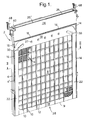
- Fig. 1 the cell 2 consisting of a split cell housing 4, 4'.
- the two housing halves 4, 4' are exactly identical and are cemented together during the assembly of the cell 2 (see also Fig. 2).
- the two major surfaces of the cell housing 4, 4' (of which only one half, 4', is seen) are provided with window-like openings 8 through which the air cathodes 6 are exposed to air.
- These openings 8 are defined by a latticework constituted of a plurality of slender, vertically-extending rails 10 linked and reinforced by horizontal webs 12 which, however, are not as thick as the rails 10.
- the rails 10 and webs 12 support and protect the air cathodes. It is also seen that, closer to the bottom of the cell, spacing between the webs 12 is reduced to provide more support where hydrostatic pressure during removal and insertion of the anode 62 (Fig. 6) is greater.
- tongues 13 and grooves 15 are provided at suitable locations along the mating edges 17, 17' (see Fig. 2).
- Similar tongue-and-groove features 14 and 16 are provided on the outer surfaces of the halves 4, 4', to facilitate the accurate joining of the cell housing and the well-defined juxtaposition, major surface to major surface, of any number of cells 2, and to prevent air leakages from between adjacent cells.
- the surfaces 18 are slightly recessed, as is seen to best advantage in Fig. 2, while the top surfaces 20 of the rails 10 (see Fig. 2) are co-planar with the rims 22 and the upper surface portion 24 of the major surfaces of the housing 4, 4'.
- an air space is created in conjunction with a similarly recessed surface 18 of an adjacent cell 2, with an access 26 at the lower edge 28 of the cell 2 and exits 30 at the upper region of the lateral edges of the cell 2.
- the outer edges 19 of the lower recessed surfaces 18 are preferably rounded or chamfered to facilitate the entry of air into the air space between adjacent cells.
- FIG. 3 shows that the rails 10 of each cell define, with similar rails 10 of adjacent cells, ducts 32 for air entering the air space from below and exiting it at the exit slots 30.
- the latter are narrowed to produce a certain back-pressure required to ensure a substantially uniform distribution of air throughout all cells 2 in a string of cells.
- the air exiting slots 30 is led through a duct (not shown) formed between the string of cells of a battery and the casing (not shown) in which the battery is accommodated.
- each cell 2 are designed with half of each edge protruding in the form of a lip 25 that, in a string of juxtaposed cells 2, will overlap the non-protruding edge half 25' of the adjacent cell 2, with the lip 25 of the adjacent cell overlapping the non-protruding edge half 25' of the first cell 2. During refueling, this will prevent dripping of the electrolyte into the air space between the cells 2. Instead, the electrolyte drips onto the lip 25 and is deflected into the interior of the cell 2.
- projections 27 are disposed along the upper portion of the recessed surface 18, the faces of which are substantially co-planar with the major surfaces of cell 2. These projections 27 prevent the recessed surfaces 18 which define the air ducts from being squeezed together to impede flow of air.
- Air in predetermined quantities is required primarily for the chemical reaction and, secondarily, for cooling.
- the proper amount of air based on a predetermined multiple of the stoichiometric quantity required for reaction and proportional to cell current, must reach all parts of the air electrode face evenly.
- the air ducts 32 must be sufficiently large to allow unimpeded airflow with a minimum of pressure drop from one end of the battery string to the other, and sufficiently small to minimize the amount of air available at the surface of the air electrode 6 when the battery is not operating (or in an emergency situation). Moreover, the air ducts 32 must be sized and positioned so that the overall volume of the battery is minimized.
- the air cathodes 6 are clearly shown in Fig. 2. They must be air-permeable, but substantially impermeable to liquid electrolytes.
- the composition of their active material 34 has been explained in the two above-mentioned prior art disclosures, and each of them is advantageously compressed upon a conductive metal screen 36 in conjunction with a further preferred supporting plastic screen 37.
- the edge 38 of the screen 36 of each cathode is soldered to a metal collector element, advantageously in the form of a copper rod 40.
- This rod 40 (of which each cell 2 has two) is accommodated in a duct formed between the internal lateral walls 42 of the cell 2 and a groove 44 in a plastic, three-sided frame 46 having an H-shaped cross-section.
- Rod 40 extends along the entire cell 2 and emerges at the upper end thereof.
- the flattened and swung-out end of rod 40 (see Figs. 1 and 5) carries a clip-like terminal 48, advantageously made of silver or any other highly conductive metal.
- the metal screens 36 are glued to the H-profile 46, while the plastic screens 37 are glued to the inside surfaces 50 of the cell 2.
- the space defined by the groove 52 of the frame 46 is filled by the anode 54, indicated by dash-dotted lines and to be described further below.
- the cathode of one cell 2 must be connected to the anode of the adjacent cell 2. Therefore, as seen in Fig. 4, the terminal clip 48 of the first cell 2 must be offset, to be located in the center plane of the second cell 2, and so on.
- the shape of the end portion 56 of rod 40 is illustrated in the top view of Fig. 5. The end portion 56 is seen to be flattened and bent so that the terminal clip 48 clears the upper lateral end of the cell 2 and is offset by the proper distance to become co-planar with the anode 6 of the second cell 2.
- Fig. 4 Further seen in Fig. 4 are shaped steel springs 58 (not shown in Fig. 1), to provide the required contact pressure which the relatively soft clips 48 alone could not produce.
- the knife-like terminals 60 of the anodes 6 are indicated by dash-dotted lines.
- FIG. 7 A variant of the guide and positioning frame 46 is seen in Fig. 7.
- the frame 46 has a U-shaped cross-section and the current collector is a flat metal bar 40 accommodated in the space formed between the lateral inside wall 42 of the cell 2 and the vertical member of the frame 46.
- the upper end (not shown) of the flat bar 40 must be suitably shaped to carry the terminal clips 48 of Fig. 4.
- Fig. 7 does not show the air electrodes 34.
- the anode is illustrated in Fig. 6. It is seen to consist of the anode mass 62 proper, advantageously consisting of porous zinc granules impregnated with a suitable electrolyte, as explained in detail in the above-mentioned European Application, and pressed onto a number of conductors 64, preferably made of copper and connected to a yoke 66 which, at its ends, carries the knife contacts 60. Except for two small breather holes (not shown), a gasket 68 seals off the cell 2 when the anode 54 is inserted. Two undercuts 70 serve for application of an extractor tool for removal of exhausted anodes.
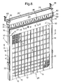
- FIG. 8 there is described a preferred embodiment of the present invention which is a modification of the embodiment as described with reference to Fig. 1, and in which identical numbers have been used to identify identical parts.
- upper surface portion 24 is provided with a fluid flow channel 72, having an inlet 74 provided in a wall 76 of a first minor surface of the cell 2.
- an outlet 80 is provided in a wall 82 of an opposite minor surface, which, together with said fluid flow channel, provides guidance for a cooling fluid (not shown) introduced into the inlet 74.
- the inlet 74 and outlet 80 both appear on the same wall, the fluid flow channel having an extended length in the general form of a long, narrow U.
- the cooling fluid is preferably a liquid; for example, a polyglycol.
- Cooling is thus provided across the upper area of the cell 2, as the cooling fluid passes along the channel 72.
- the electrolyte (not shown) which is contained in the cell open space and is in contact with the rear face of the channel 72, thus transfers part of its excess heat to the cooling fluid in the well-known heat exchanger process.
- the fluid flow channel 72 is in the form of a labyrinth 86 to maximize heat transfer.
- Other forms of fluid flow channels such as a serpentine path, are also feasible.
- Convective circulation of the electrolyte within the open space of cell 2 is stimulated by the effect of the heat transfer at the top of the cell, causing a greater temperature gradient within the electrolyte within the cell, thereby increasing cooling effectiveness. It may be further noted that the vibration and other motions present in moving road vehicles are also helpful in this regard.
- the fluid flow channel 72 is integrally formed as a meandering groove provided in the upper surface portion 24.
- a cover panel which has been removed in the drawing to show the channel 72, seals and defines the flow path within the labyrinth 86.
- the flow channel is found within the upper surface portion 24; there is then no need for a cover panel.
Landscapes
- Chemical & Material Sciences (AREA)
- Chemical Kinetics & Catalysis (AREA)
- Electrochemistry (AREA)
- General Chemical & Material Sciences (AREA)
- Engineering & Computer Science (AREA)
- Manufacturing & Machinery (AREA)
- Hybrid Cells (AREA)
Applications Claiming Priority (4)
| Application Number | Priority Date | Filing Date | Title |
|---|---|---|---|
| US213674 | 1994-03-15 | ||
| US08/213,674 US5366822A (en) | 1994-03-15 | 1994-03-15 | Cell for a metal-air battery |
| US08/275,588 US5447805A (en) | 1994-03-15 | 1994-07-15 | Cell for a metal-air battery |
| US275588 | 1994-07-15 |
Publications (1)
| Publication Number | Publication Date |
|---|---|
| EP0673076A1 true EP0673076A1 (fr) | 1995-09-20 |
Family
ID=26908294
Family Applications (1)
| Application Number | Title | Priority Date | Filing Date |
|---|---|---|---|
| EP19940307391 Ceased EP0673076A1 (fr) | 1994-03-15 | 1994-10-07 | Elément pour batterie métal-air |
Country Status (3)
| Country | Link |
|---|---|
| US (1) | US5447805A (fr) |
| EP (1) | EP0673076A1 (fr) |
| JP (1) | JPH07272769A (fr) |
Cited By (5)
| Publication number | Priority date | Publication date | Assignee | Title |
|---|---|---|---|---|
| WO1998053517A1 (fr) * | 1997-05-19 | 1998-11-26 | Aer Energy Resources, Inc. | Procede et appareil de raccordement d'elements metal-air |
| EP0952622A1 (fr) * | 1998-03-24 | 1999-10-27 | Electric Fuel (E.F.L.) Limited | Elément pour batterie métal-air |
| WO2008035875A1 (fr) | 2006-09-18 | 2008-03-27 | Lg Chem, Ltd. | Module de batterie et bloc-batterie de grande et moyenne taille contenant ce module |
| WO2010054939A1 (fr) | 2008-11-13 | 2010-05-20 | Continental Automotive Gmbh | Support de cellule, cellule accumulatrice d’énergie, empilement de supports de cellules et accumulateur d’énergie à plusieurs cellules |
| DE102014118171A1 (de) | 2014-12-08 | 2016-06-09 | Kunkel + Partner GmbH & Co. KG | Batteriezelle zum modularen Aufbau einer wiederaufladbaren Metall-Luft Batterie, Halteeinrichtung für eine Batteriezelle und Batteriemodul mit mehreren Batteriezellen |
Families Citing this family (44)
| Publication number | Priority date | Publication date | Assignee | Title |
|---|---|---|---|---|
| US6057052A (en) * | 1995-05-25 | 2000-05-02 | Electric Fuel (E.F.L.) Ltd. | Cell for a metal-air battery |
| US5919582A (en) * | 1995-10-18 | 1999-07-06 | Aer Energy Resources, Inc. | Diffusion controlled air vent and recirculation air manager for a metal-air battery |
| US5691074A (en) * | 1995-10-18 | 1997-11-25 | Aer Energy Resources, Inc. | Diffusion controlled air vent for a metal-air battery |
| US7531262B1 (en) * | 1996-07-09 | 2009-05-12 | Maria Simpson | High-volume-manufacture fuel cell arrangement and method for production thereof |
| US6106962A (en) | 1997-09-24 | 2000-08-22 | Aer Energy Resources Inc. | Air manager control using cell voltage as auto-reference |
| US6472093B2 (en) | 1997-10-06 | 2002-10-29 | Reveo, Inc. | Metal-air fuel cell battery systems having a metal-fuel card storage cartridge, insertable within a fuel cartridge insertion port, containing a supply of substantially planar discrete metal-fuel cards, and fuel card transport mechanisms therein |
| US6558829B1 (en) | 1997-10-06 | 2003-05-06 | Reveo, Inc. | Appliance with refuelable and rechargeable metal-air fuel cell battery power supply unit integrated therein |
| US6296960B1 (en) | 1997-10-06 | 2001-10-02 | Reveo, Inc. | System and method for producing electrical power using metal-air fuel cell battery technology |
| US6306534B1 (en) | 1997-10-06 | 2001-10-23 | Reveo, Inc. | Metal-air fuel cell battery systems employing means for discharging and recharging metal-fuel cards |
| US6348277B1 (en) | 1997-10-06 | 2002-02-19 | Reveo, Inc. | Method of and system for producing and supplying electrical power to an electrical power consuming device using a metal-air fuel cell battery (FCB) module and a supply of metal-fuel cards |
| US6451463B1 (en) | 1997-10-06 | 2002-09-17 | Reveo, Inc. | Electro-chemical power generation systems employing arrays of electronically-controllable discharging and/or recharging cells within a unity support structure |
| US6569555B1 (en) | 1997-10-06 | 2003-05-27 | Reveo, Inc. | Refuelable and rechargeable metal-air fuel cell battery power supply unit for integration into an appliance |
| US6087029A (en) * | 1998-01-06 | 2000-07-11 | Aer Energy Resources, Inc. | Water recovery using a bi-directional air exchanger for a metal-air battery |
| US6299998B1 (en) | 1999-03-15 | 2001-10-09 | Reveo, Inc. | Movable anode fuel cell battery |
| USD481993S1 (en) | 1999-08-13 | 2003-11-11 | The Gillette Company | Battery |
| US6492046B1 (en) | 1999-08-13 | 2002-12-10 | The Gillette Company | Metal-air battery |
| US6232007B1 (en) | 1999-08-13 | 2001-05-15 | The Gillette Company | Metal-air battery container |
| US6641947B1 (en) | 1999-09-21 | 2003-11-04 | The Gillette Company | Air manager system for metal air battery |
| JP4283951B2 (ja) * | 1999-10-08 | 2009-06-24 | パナソニック株式会社 | 密閉角形電池 |
| US6653003B1 (en) | 1999-10-12 | 2003-11-25 | Reveo Inc. | Fuel cell support and electrical interconnector |
| US6558825B1 (en) | 2000-05-12 | 2003-05-06 | Reveo, Inc. | Fuel containment and recycling system |
| USD459297S1 (en) | 2000-09-19 | 2002-06-25 | The Gillette Company | Battery |
| US20020150814A1 (en) * | 2001-02-01 | 2002-10-17 | Causton Brian Edward | Battery |
| US6630262B2 (en) | 2001-03-09 | 2003-10-07 | De-Qian Yang | Metal-gas cell battery with soft pocket |
| US7547487B1 (en) * | 2004-05-18 | 2009-06-16 | Ovonic Battery Company, Inc. | Multi-cell battery assembly |
| US8080326B2 (en) * | 2009-05-26 | 2011-12-20 | The Invention Science Fund I, Llc | Method of operating an electrical energy storage device using microchannels during charge and discharge |
| US20100304259A1 (en) * | 2009-05-26 | 2010-12-02 | Searete Llc. A Limited Liability Corporation Of The State Of Delaware | Method of operating an electrical energy storage device or an electrochemical energy generation device using high thermal conductivity materials during charge and discharge |
| US8715875B2 (en) * | 2009-05-26 | 2014-05-06 | The Invention Science Fund I, Llc | System and method of operating an electrical energy storage device or an electrochemical energy generation device using thermal conductivity materials based on mobile device states and vehicle states |
| US20100304258A1 (en) * | 2009-05-26 | 2010-12-02 | Chan Alistair K | System and method of altering temperature of an electrical energy storage device or an electrochemical energy generation device using high thermal conductivity materials |
| US8802266B2 (en) * | 2009-05-26 | 2014-08-12 | The Invention Science Fund I, Llc | System for operating an electrical energy storage device or an electrochemical energy generation device using microchannels based on mobile device states and vehicle states |
| TW201119122A (en) * | 2009-11-17 | 2011-06-01 | Genius Toy Taiwan Co Ltd | Fuel cell module |
| US9444105B2 (en) | 2011-11-04 | 2016-09-13 | Fluidic, Inc. | Immersible gaseous oxidant cathode for electrochemical cell system |
| CN102931362A (zh) * | 2012-09-20 | 2013-02-13 | 北京九能京通新能源科技有限公司 | 空气电池壳及其注塑方法 |
| JP2017084650A (ja) * | 2015-10-29 | 2017-05-18 | シャープ株式会社 | 金属空気組電池 |
| KR20170056821A (ko) | 2015-11-16 | 2017-05-24 | 주식회사 이엠따블유에너지 | 공기-아연 전지 모듈 |
| CN105810976B (zh) * | 2016-04-29 | 2018-11-02 | 苏州讴德新能源发展有限公司 | 一种易组装的单元燃料电池结构及燃料电池装置 |
| BR112019008041A2 (pt) | 2016-10-21 | 2019-07-02 | Nantenergy Inc | elétrodo de combustível corrugado |
| WO2019133702A1 (fr) | 2017-12-29 | 2019-07-04 | Staq Energy, Inc. | Batteries secondaires alcalines scellées à longue durée de vie |
| MA53343A (fr) | 2018-07-27 | 2022-03-23 | Form Energy Inc | Électrodes négatives pour cellules électrochimiques |
| US12294086B2 (en) | 2019-07-26 | 2025-05-06 | Form Energy, Inc. | Low cost metal electrodes |
| CN112701325B (zh) * | 2019-10-22 | 2025-07-22 | 黄宗洪 | 金属空气电池电堆的主动正压供氧系统 |
| WO2022104417A1 (fr) * | 2020-11-17 | 2022-05-27 | Tritium Holdings Pty Ltd | Ensemble pour un chargeur de véhicule électrique |
| CN113054314B (zh) * | 2021-03-16 | 2022-09-13 | 岭南师范学院 | 一种多散热模式作用下的汽车动力电池强化传热系统 |
| KR20240141800A (ko) | 2022-01-28 | 2024-09-27 | 폼 에너지 인코퍼레이티드 | 양면 밀봉형 기체 확산 전극 |
Citations (7)
| Publication number | Priority date | Publication date | Assignee | Title |
|---|---|---|---|---|
| US3457115A (en) * | 1965-12-03 | 1969-07-22 | Gen Electric | Gas-depolarized electrical power unit with filter means |
| DE1805819A1 (de) * | 1967-11-02 | 1969-07-31 | Energy Conversion Ltd | Abstuetzglied fuer eine Kathode einer gasdepolarisierten Zelle in einer Batterie |
| DE1905167A1 (de) * | 1968-02-02 | 1969-08-28 | Leesona Corp | Elektrode fuer eine elektrochemische Zelle |
| GB1225045A (en) * | 1968-05-13 | 1971-03-17 | Energy Conversion Ltd | Improvements in and relating to electrochemical cells |
| US3592692A (en) * | 1970-02-19 | 1971-07-13 | Us Navy | Apparatus for battery cell connections |
| EP0311275A2 (fr) * | 1987-09-25 | 1989-04-12 | Alcan International Limited | Batterie métal-air à électrolyte circulant |
| EP0405558A2 (fr) * | 1989-06-29 | 1991-01-02 | Eltech Systems Corporation | Batterie métal-air à anodes facilement amovibles |
Family Cites Families (4)
| Publication number | Priority date | Publication date | Assignee | Title |
|---|---|---|---|---|
| US4620111A (en) * | 1984-06-25 | 1986-10-28 | Duracell Inc. | Auxiliary portable power supply |
| US4640874A (en) * | 1985-07-29 | 1987-02-03 | Duracell Inc. | Metal/air cell |
| JPH04366547A (ja) * | 1991-06-12 | 1992-12-18 | Matsushita Electric Ind Co Ltd | ガス減極式構成電池 |
| US5366822A (en) * | 1994-03-15 | 1994-11-22 | Electric Fuel (E.F.L.) Ltd. | Cell for a metal-air battery |
-
1994
- 1994-07-15 US US08/275,588 patent/US5447805A/en not_active Expired - Fee Related
- 1994-10-07 EP EP19940307391 patent/EP0673076A1/fr not_active Ceased
- 1994-11-02 JP JP6269691A patent/JPH07272769A/ja active Pending
Patent Citations (7)
| Publication number | Priority date | Publication date | Assignee | Title |
|---|---|---|---|---|
| US3457115A (en) * | 1965-12-03 | 1969-07-22 | Gen Electric | Gas-depolarized electrical power unit with filter means |
| DE1805819A1 (de) * | 1967-11-02 | 1969-07-31 | Energy Conversion Ltd | Abstuetzglied fuer eine Kathode einer gasdepolarisierten Zelle in einer Batterie |
| DE1905167A1 (de) * | 1968-02-02 | 1969-08-28 | Leesona Corp | Elektrode fuer eine elektrochemische Zelle |
| GB1225045A (en) * | 1968-05-13 | 1971-03-17 | Energy Conversion Ltd | Improvements in and relating to electrochemical cells |
| US3592692A (en) * | 1970-02-19 | 1971-07-13 | Us Navy | Apparatus for battery cell connections |
| EP0311275A2 (fr) * | 1987-09-25 | 1989-04-12 | Alcan International Limited | Batterie métal-air à électrolyte circulant |
| EP0405558A2 (fr) * | 1989-06-29 | 1991-01-02 | Eltech Systems Corporation | Batterie métal-air à anodes facilement amovibles |
Cited By (10)
| Publication number | Priority date | Publication date | Assignee | Title |
|---|---|---|---|---|
| WO1998053517A1 (fr) * | 1997-05-19 | 1998-11-26 | Aer Energy Resources, Inc. | Procede et appareil de raccordement d'elements metal-air |
| US5891589A (en) * | 1997-05-19 | 1999-04-06 | Aer Energy Resources, Inc. | Method and apparatus for joining metal-air cells |
| US6051328A (en) * | 1997-05-19 | 2000-04-18 | Aer Energy Resources, Inc. | Method and apparatus for joining metal-air cells |
| EP0952622A1 (fr) * | 1998-03-24 | 1999-10-27 | Electric Fuel (E.F.L.) Limited | Elément pour batterie métal-air |
| WO2008035875A1 (fr) | 2006-09-18 | 2008-03-27 | Lg Chem, Ltd. | Module de batterie et bloc-batterie de grande et moyenne taille contenant ce module |
| EP2064761A4 (fr) * | 2006-09-18 | 2011-01-19 | Lg Chemical Ltd | Module de batterie et bloc-batterie de grande et moyenne taille contenant ce module |
| WO2010054939A1 (fr) | 2008-11-13 | 2010-05-20 | Continental Automotive Gmbh | Support de cellule, cellule accumulatrice d’énergie, empilement de supports de cellules et accumulateur d’énergie à plusieurs cellules |
| DE102008057210B4 (de) | 2008-11-13 | 2023-05-04 | Vitesco Technologies GmbH | Zellhalter, Energiespeicherzelle, Zellhalterstapel und Mehrzellenenergiespeicher |
| DE102014118171A1 (de) | 2014-12-08 | 2016-06-09 | Kunkel + Partner GmbH & Co. KG | Batteriezelle zum modularen Aufbau einer wiederaufladbaren Metall-Luft Batterie, Halteeinrichtung für eine Batteriezelle und Batteriemodul mit mehreren Batteriezellen |
| DE102014118171B4 (de) | 2014-12-08 | 2024-12-19 | KUNKEL + Partner Ingenieure GmbH | Batteriezelle zum modularen Aufbau einer wiederaufladbaren Metall-Luft Batterie, Halteeinrichtung für eine Batteriezelle und Batteriemodul mit mehreren Batteriezellen |
Also Published As
| Publication number | Publication date |
|---|---|
| JPH07272769A (ja) | 1995-10-20 |
| US5447805A (en) | 1995-09-05 |
Similar Documents
| Publication | Publication Date | Title |
|---|---|---|
| US5447805A (en) | Cell for a metal-air battery | |
| US5366822A (en) | Cell for a metal-air battery | |
| US5904999A (en) | Air-cooled metal-air battery | |
| US4871627A (en) | Multi-cell metal/air battery | |
| US6482542B1 (en) | Integrated sealed secondary battery | |
| US6821673B1 (en) | Battery module, and rechargeable battery for constituting the battery module | |
| US5424143A (en) | Air-cooled, metal-air battery | |
| US6586132B1 (en) | Sealed battery pack | |
| US6312851B1 (en) | Sealed secondary battery assembly | |
| EP0700110A1 (fr) | Batterie refroidie du type zinc/oxygène | |
| US5650241A (en) | Metal-air cell battery | |
| JPH08148187A (ja) | 温度制御機構を備えたバッテリ組立体 | |
| JPH10334953A (ja) | 電気化学セルのバッテリの温度制御装置 | |
| US4988581A (en) | Metal-air bipolar cell unit | |
| PL116452B1 (en) | Two-pole electrode unit | |
| JP2005536033A (ja) | 電気化学電池の流体流れの制御 | |
| CN202454638U (zh) | 一种方形二次电池 | |
| US4590135A (en) | Fuel cell structures | |
| JP2001504979A (ja) | 液体冷却式の燃料電池バッテリー | |
| JPS60249260A (ja) | 燃料電池 | |
| GB2228137A (en) | Cooled Na-S cell | |
| CA2274826C (fr) | Systeme de refrigeration pour batterie de piles a combustible | |
| JPH09237617A (ja) | 組電池 | |
| US5919584A (en) | Fuel cell | |
| JP2000251953A (ja) | 集合型密閉二次電池 |
Legal Events
| Date | Code | Title | Description |
|---|---|---|---|
| PUAI | Public reference made under article 153(3) epc to a published international application that has entered the european phase |
Free format text: ORIGINAL CODE: 0009012 |
|
| AK | Designated contracting states |
Kind code of ref document: A1 Designated state(s): AT BE CH DE DK ES FR GB GR IE IT LI LU MC NL PT SE |
|
| RAX | Requested extension states of the european patent have changed |
Free format text: SI |
|
| 17P | Request for examination filed |
Effective date: 19960307 |
|
| 17Q | First examination report despatched |
Effective date: 19960730 |
|
| GRAG | Despatch of communication of intention to grant |
Free format text: ORIGINAL CODE: EPIDOS AGRA |
|
| STAA | Information on the status of an ep patent application or granted ep patent |
Free format text: STATUS: THE APPLICATION HAS BEEN REFUSED |
|
| 18R | Application refused |
Effective date: 19980710 |