EP0673092B1 - Optisch gepumpter bistabiler Laser - Google Patents
Optisch gepumpter bistabiler Laser Download PDFInfo
- Publication number
- EP0673092B1 EP0673092B1 EP95103621A EP95103621A EP0673092B1 EP 0673092 B1 EP0673092 B1 EP 0673092B1 EP 95103621 A EP95103621 A EP 95103621A EP 95103621 A EP95103621 A EP 95103621A EP 0673092 B1 EP0673092 B1 EP 0673092B1
- Authority
- EP
- European Patent Office
- Prior art keywords
- laser
- las
- optically pumped
- bistable
- resonator
- Prior art date
- Legal status (The legal status is an assumption and is not a legal conclusion. Google has not performed a legal analysis and makes no representation as to the accuracy of the status listed.)
- Expired - Lifetime
Links
- 239000000835 fiber Substances 0.000 claims description 46
- 230000003287 optical effect Effects 0.000 claims description 35
- 230000007704 transition Effects 0.000 claims description 18
- 238000010168 coupling process Methods 0.000 claims description 7
- 238000005859 coupling reaction Methods 0.000 claims description 7
- 238000011084 recovery Methods 0.000 claims description 2
- 230000005284 excitation Effects 0.000 description 8
- 230000001419 dependent effect Effects 0.000 description 7
- 230000005281 excited state Effects 0.000 description 6
- 239000006096 absorbing agent Substances 0.000 description 5
- 230000008878 coupling Effects 0.000 description 5
- 229910052691 Erbium Inorganic materials 0.000 description 4
- 238000010521 absorption reaction Methods 0.000 description 4
- UYAHIZSMUZPPFV-UHFFFAOYSA-N erbium Chemical compound [Er] UYAHIZSMUZPPFV-UHFFFAOYSA-N 0.000 description 4
- 230000008901 benefit Effects 0.000 description 3
- 238000000034 method Methods 0.000 description 3
- 230000008569 process Effects 0.000 description 3
- 230000000712 assembly Effects 0.000 description 2
- 238000000429 assembly Methods 0.000 description 2
- 230000005283 ground state Effects 0.000 description 2
- 238000003780 insertion Methods 0.000 description 2
- 230000037431 insertion Effects 0.000 description 2
- 230000005855 radiation Effects 0.000 description 2
- 229910013641 LiNbO 3 Inorganic materials 0.000 description 1
- WHXSMMKQMYFTQS-UHFFFAOYSA-N Lithium Chemical compound [Li] WHXSMMKQMYFTQS-UHFFFAOYSA-N 0.000 description 1
- 229910004298 SiO 2 Inorganic materials 0.000 description 1
- VYPSYNLAJGMNEJ-UHFFFAOYSA-N Silicium dioxide Chemical compound O=[Si]=O VYPSYNLAJGMNEJ-UHFFFAOYSA-N 0.000 description 1
- 230000003321 amplification Effects 0.000 description 1
- 230000005540 biological transmission Effects 0.000 description 1
- 230000015572 biosynthetic process Effects 0.000 description 1
- 230000008859 change Effects 0.000 description 1
- 238000010276 construction Methods 0.000 description 1
- 230000000694 effects Effects 0.000 description 1
- 229910052744 lithium Inorganic materials 0.000 description 1
- 238000004519 manufacturing process Methods 0.000 description 1
- 238000003199 nucleic acid amplification method Methods 0.000 description 1
- 230000010363 phase shift Effects 0.000 description 1
Images
Classifications
-
- H—ELECTRICITY
- H01—ELECTRIC ELEMENTS
- H01S—DEVICES USING THE PROCESS OF LIGHT AMPLIFICATION BY STIMULATED EMISSION OF RADIATION [LASER] TO AMPLIFY OR GENERATE LIGHT; DEVICES USING STIMULATED EMISSION OF ELECTROMAGNETIC RADIATION IN WAVE RANGES OTHER THAN OPTICAL
- H01S3/00—Lasers, i.e. devices using stimulated emission of electromagnetic radiation in the infrared, visible or ultraviolet wave range
- H01S3/05—Construction or shape of optical resonators; Accommodation of active medium therein; Shape of active medium
- H01S3/06—Construction or shape of active medium
- H01S3/063—Waveguide lasers, i.e. whereby the dimensions of the waveguide are of the order of the light wavelength
- H01S3/067—Fibre lasers
-
- H—ELECTRICITY
- H01—ELECTRIC ELEMENTS
- H01S—DEVICES USING THE PROCESS OF LIGHT AMPLIFICATION BY STIMULATED EMISSION OF RADIATION [LASER] TO AMPLIFY OR GENERATE LIGHT; DEVICES USING STIMULATED EMISSION OF ELECTROMAGNETIC RADIATION IN WAVE RANGES OTHER THAN OPTICAL
- H01S3/00—Lasers, i.e. devices using stimulated emission of electromagnetic radiation in the infrared, visible or ultraviolet wave range
- H01S3/10—Controlling the intensity, frequency, phase, polarisation or direction of the emitted radiation, e.g. switching, gating, modulating or demodulating
- H01S3/102—Controlling the intensity, frequency, phase, polarisation or direction of the emitted radiation, e.g. switching, gating, modulating or demodulating by controlling the active medium, e.g. by controlling the processes or apparatus for excitation
- H01S3/1022—Controlling the intensity, frequency, phase, polarisation or direction of the emitted radiation, e.g. switching, gating, modulating or demodulating by controlling the active medium, e.g. by controlling the processes or apparatus for excitation by controlling the optical pumping
-
- G—PHYSICS
- G02—OPTICS
- G02F—OPTICAL DEVICES OR ARRANGEMENTS FOR THE CONTROL OF LIGHT BY MODIFICATION OF THE OPTICAL PROPERTIES OF THE MEDIA OF THE ELEMENTS INVOLVED THEREIN; NON-LINEAR OPTICS; FREQUENCY-CHANGING OF LIGHT; OPTICAL LOGIC ELEMENTS; OPTICAL ANALOGUE/DIGITAL CONVERTERS
- G02F3/00—Optical logic elements; Optical bistable devices
- G02F3/02—Optical bistable devices
- G02F3/026—Optical bistable devices based on laser effects
-
- H—ELECTRICITY
- H01—ELECTRIC ELEMENTS
- H01S—DEVICES USING THE PROCESS OF LIGHT AMPLIFICATION BY STIMULATED EMISSION OF RADIATION [LASER] TO AMPLIFY OR GENERATE LIGHT; DEVICES USING STIMULATED EMISSION OF ELECTROMAGNETIC RADIATION IN WAVE RANGES OTHER THAN OPTICAL
- H01S3/00—Lasers, i.e. devices using stimulated emission of electromagnetic radiation in the infrared, visible or ultraviolet wave range
- H01S3/05—Construction or shape of optical resonators; Accommodation of active medium therein; Shape of active medium
- H01S3/06—Construction or shape of active medium
- H01S3/063—Waveguide lasers, i.e. whereby the dimensions of the waveguide are of the order of the light wavelength
- H01S3/067—Fibre lasers
- H01S3/06791—Fibre ring lasers
-
- H—ELECTRICITY
- H01—ELECTRIC ELEMENTS
- H01S—DEVICES USING THE PROCESS OF LIGHT AMPLIFICATION BY STIMULATED EMISSION OF RADIATION [LASER] TO AMPLIFY OR GENERATE LIGHT; DEVICES USING STIMULATED EMISSION OF ELECTROMAGNETIC RADIATION IN WAVE RANGES OTHER THAN OPTICAL
- H01S3/00—Lasers, i.e. devices using stimulated emission of electromagnetic radiation in the infrared, visible or ultraviolet wave range
- H01S3/14—Lasers, i.e. devices using stimulated emission of electromagnetic radiation in the infrared, visible or ultraviolet wave range characterised by the material used as the active medium
- H01S3/16—Solid materials
- H01S3/1601—Solid materials characterised by an active (lasing) ion
- H01S3/1603—Solid materials characterised by an active (lasing) ion rare earth
- H01S3/1608—Solid materials characterised by an active (lasing) ion rare earth erbium
-
- Y—GENERAL TAGGING OF NEW TECHNOLOGICAL DEVELOPMENTS; GENERAL TAGGING OF CROSS-SECTIONAL TECHNOLOGIES SPANNING OVER SEVERAL SECTIONS OF THE IPC; TECHNICAL SUBJECTS COVERED BY FORMER USPC CROSS-REFERENCE ART COLLECTIONS [XRACs] AND DIGESTS
- Y10—TECHNICAL SUBJECTS COVERED BY FORMER USPC
- Y10S—TECHNICAL SUBJECTS COVERED BY FORMER USPC CROSS-REFERENCE ART COLLECTIONS [XRACs] AND DIGESTS
- Y10S372/00—Coherent light generators
- Y10S372/703—Optical isolater
Definitions
- the invention relates to an optically pumped and through optical pulse controlled laser.
- the fiber laser is a ring laser with an erbium-doped fiber, an optical filter, a fiber modulator and several couplers.
- the Fiber modulator is controlled by optical pulses.
- the optical pulses briefly change the refractive index of the Fiber modulator, whereupon the phase of the erbium doped fiber generated continuous radiation (CW operation) changes. This leads to interference phenomena and thus for the formation of optical pulses at the laser output.
- CW operation continuous radiation
- a bistable laser is known from US Pat. No. 3,440,562 and US Pat. No. 5,128,800 to which a drinkable absorber is placed in the resonator.
- the absorber has one Signal input through which a control signal can be supplied. By the Control signal, the absorption coefficient of the absorber can be changed.
- the Laser is kept in a first inactive state by the pump light in the laser-active medium generated light emissions in the absorber due to corresponding absorption coefficients are completely absorbed, so that stimulated emissions in the laser-active medium can be suppressed.
- a particular advantage of the invention lies in the possibility the bistable laser in addition to generating optical pulses to use as a flip-flop.
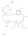
- Fig. 1 shows the schematic shown construction of an embodiment of the bistable laser according to the invention.
- the bistable laser LAS contains an erbium doped fiber ER as laser active Medium, a fiber resonator as a resonator and a Pump light source PUMP as an energy source. Furthermore, the bistable laser LAS an optical isolator ISO, one wavelength-dependent coupler WDM and an asymmetrical FC fiber coupler.
- the fiber resonator is designed as a ring resonator RES.
- RES the erbium-doped fiber in series ER, the asymmetrical fiber coupler FC, the optical isolator ISO and the wavelength-dependent coupler WDM inserted.
- the wavelength-dependent coupler WDM has three connections. Two connections are used for insertion into the ring resonator RES. The third connection is with the pump light source PUMP connected. The pump light source PUMP generates pump light that via the wavelength-dependent coupler WDM in the Ring resonator is coupled. The pump light has one shorter wavelength than the signal light.
- the wavelength-dependent coupler WDM thus couples light from two Fibers and with different wavelengths into one fiber.
- the ISO optical isolator almost only lets light in one direction pass lossless, in the other direction it is Attenuation of light more than 30 dB.
- the ISO optical isolator serves among other things a direction of rotation for the signal light to be determined. It has two connections and is thus in the Ring resonator RES inserted that its forward direction is the same the desired direction of the signal light.
- the asymmetrical fiber coupler FC has four connections. Two Connections are used for insertion into the ring resonator RES. The third connection forms the input IN of the bistable laser LAS, the fourth connection the output OUT of the bistable laser READ. The input IN (output OUT) becomes asymmetrical Signal light coupled into (off) the ring resonator RES (uncoupled). For example, 20% of the signal light from the Ring resonator RES decoupled and is at the output OUT of the bistable laser LAS available while the remaining 80 % of the signal light remain in the ring resonator RES and the Maintain operation of the bistable laser LAS.
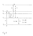
- the pump light source PUMP generates pump light of the wavelength 800 nm. This pump light leads in the erbium-doped fiber ER to stimulate an excited inactive state, what will be discussed in more detail with reference to FIG. 2.
- the bistable Laser LAS is in the pumped state and without concern of optical signals at the IN input in an excited inactive state, i.e. it does not emit light.
- the bistable laser goes on when signal light is applied to the IN input LAS from the excited inactive state to the laser active Condition about.
- the signal light can e.g. from optical pulses consist. With pulsed signal light, the choice of Pulse duration and the pulse repetition frequency of the optical pulses bistable laser LAS in several different states operate. The following are two modes of operation and three uses for the optical Message transmission for the bistable laser LAS described.
- the bistable laser is over controlled the input IN so that it works in pulse mode.
- optical pulses are periodically transmitted via the input IN coupled the ring resonator RES.
- the pulse repetition frequency of the optical pulses corresponds to an integer multiple of Circulation frequency f of the light in the ring resonator RES.
- the coupled optical Pulses induce themselves in the excited inactive state erbium-doped fiber ER stimulated emissions, so that an amplification of the optical pulses occurs.
- At the Output OUT of the bistable laser LAS are therefore opposed amplified optical pulses are available to the input pulses.
- the pulse repetition frequency of the output pulses is equal to that Pulse repetition frequency of the input pulses.
- the bistable laser LAS e.g. used as a pulse generator become.
- Optical pulses, e.g. about a Telecommunication networks that have been transmitted can be bistable Laser LAS are prepared and reinforced and are on Output of the bistable laser LAS as clock signals e.g. For clock recovery in optical signal processing for Available.
- the optical pulses are e.g.
- the frequency of the Base clock corresponds to an integer multiple of Circulation frequency f of the light in the ring resonator RES.
- the consequence of bit signals passes through the ring resonator RES. Every 1st generates a stimulated emission in the eribum-doped Fiber ER. Due to the almost statistical distribution of the logical states 1 and 0 can thus be determined according to a certain Time period of the basic clock from the sequence of bit signals be filtered out and stands at the output as a clock signal for optical signal processing is available.
- the second mode of operation is the bistable laser LAS controlled via the IN input so that it is in CW mode (Emitting continuous radiation) works.
- This will an optical pulse into the ring resonator via the IN input RES coupled.
- the pulse duration of the optical pulse must at least the round trip time (1 / f) of the light in the ring resonator RES correspond. It must be ensured that the optical Pulse spiked as many stimulated emissions in the erbium Fiber ER induces the CW to be stimulated by the Emissions can be maintained.
- the bistable laser LAS can e.g. as Flip-flop can be used.
- the bistable laser LAS tilts by coupling an optical pulse from excited inactive state into the laser active state of the CW operation.
- the resetting of the bistable laser LAS in the excited inactive state can e.g. by briefly Switch off the pump light.
- the fiber resonator RES is designed as a ring resonator RES.
- the invention can also be applied to a resonator other than the ring resonator RES, for example a Fabry-Perot resonator.
- the fiber resonator RES and also the entire bistable laser LAS can be designed as a monolithically integrated circuit. Quartz glass SiO 2 or lithium niobath LiNbO 3 then serves as the laser-active medium.
- the fibers used in the embodiment advantageously for reasons of stability polarization-maintaining single-mode fibers.
- an asymmetrical fiber coupler FC both for coupling in and out of light used.
- FC can also use two separate asymmetrical fiber couplers, one for coupling in and the other one for coupling out light, be used.
- the two separate asymmetrical ones Fiber couplers are then inserted into the ring resonator RES inserted that first in the direction of the signal light asymmetrical fiber coupler for decoupling and then the asymmetrical fiber coupler for coupling light inserted becomes. This has the advantage that crosstalk from Input signals largely on the output signals is suppressed.
- Electrons at energy level E 1 can be stimulated to stimulate emissions on the one hand by light of wavelengths 1530 nm to 1570 nm and on the other hand can be excited by pump light of wavelength 800 nm from energy level E 1 to energy level E 4 (excitation from an excited state).
- the erbium-doped fiber is pumped with pump light of wavelength 800 nm.
- the result of this is that electrons are excited from the ground state, ie from energy level E 0 to energy level E 3 (transition 1).
- the lifespan of the electrons in energy levels E 3 and E 2 is short compared to the lifespan of the electrons in energy level E 1 .
- the electrons excited into energy level E 3 possibly above energy level E 2 , pass through non-radiative transitions into energy level E 1 (transition 2).
- the pump light of wavelength 800 nm also has the consequence that the electrons excited into energy level E 1 are excited into energy level E 4 (transition 3) (excitation from excited state).
- the electrons excited into energy level E 4 pass through non-radiative transitions into energy level E 1 (transition 4).
- the processes of excitation of electrons from energy level E 1 to energy level E 4 (transition 3) and the non-radiative transitions of electrons from energy level E 4 to energy level E 1 (transition 4) are now repeated continuously, so that the bistable laser is in the excited, inactive state remains.
- the process of stimulated emission only occurs when light of wavelengths 1530 nm to 1570 nm, which corresponds to the transition from energy level E 1 to energy level E 0 , is emitted (transition 5).
- the processes of stimulated emission (transition 5) and excitation from an excited state (transition 3) compete with each other. The more signal light that is irradiated into the erbium-doped fiber, the less the excitation from the excited state (transition 3) occurs.
- the bistable laser then changes to the laser-active state.
- the erbium-doped fiber is pumped with pump light of a wavelength (800 nm).
- the invention can also be applied to a pump light with two wavelengths, for example 800 nm and 980 nm.
- the pump light source PUMP then contains, for example, two lasers and a wavelength-dependent coupler. One laser is used to generate 800 nm pump light, the other laser is used to generate 980 nm pump light.
- the 800 nm pump light and the 980 nm pump light are coupled into a fiber via the wavelength-dependent coupler, so that pump light with two wavelengths can be coupled into the resonator RES of the bistable laser LAS via a fiber.
- the pump light of wavelength 980 nm can be used to excite electrons from energy level E 0 to energy level E 2 (and thus to energy level E 1 ) and the pump light of wavelength 800 nm can be used to generate the excitation from the excited state (transition 3).
- the excitation of electrons from energy level E 0 to energy level E 1 is more effective with 980 nm pump light than with 800 nm pump light.
- a higher output power is possible for the bistable laser LAS when using pump light with two wavelengths.
- the information for the absolute values of the wavelengths is exemplary. For example, light of wavelengths in the range from 780 nm to 850 nm can be used to generate the excitation from the excited state (transition 3).
- a bistable laser LAS with a Erbium-doped fiber is described as a laser-active medium.
- the erbium-doped fiber one with a another element from the group of rare earths Fiber can be used as a laser active medium.
Landscapes
- Physics & Mathematics (AREA)
- Electromagnetism (AREA)
- Engineering & Computer Science (AREA)
- Plasma & Fusion (AREA)
- Optics & Photonics (AREA)
- Lasers (AREA)
Description
- Fig. 1
- eine schematische Darstellung eines Ausführungsbeispiels des erfindungsgemäßen bistabilen Lasers, und
- Fig. 2
- ein Niveausystem einer Erbium dotierten Faser eines erfingungsgemäßen bistabilen Lasers.
Claims (11)
- Optisch gepumpter bistabiler Laser (LAS) mit einem laseraktiven Medium (ER), mit einem Resonator (RES), mit einer Pumplichtquelle ( PUMP), durch deren Pumplicht das laseraktive Medium (ER) in einen angeregten inaktiven Zustand gebracht werden kann, in dem Elektronen fortlaufend von einem ersten (E1), energetisch über dem Grundzustand (E0) liegenden Energieniveau in ein zweites (E4), energetisch über dem ersten liegenden Energieniveau angeregt werden, und mit einer Einkoppelvorrichtung (FC) zum Einkoppeln von Signallicht welches den Übergang vom ersten Energieniveau (E1) zum Grundzustand (E0) entspricht, durch das sich das im angeregten inaktiven Zustand befindliche laseraktive Medium (ER) in einen laseraktiven Zustand gebracht werden kann.
- Optisch gepumpter bistabiler Laser (LAS) nach Anspruch 1, dadurch gekennzeichnet, daß das laseraktive Medium (ER) eine mit einem Element der Gruppe der seltenen Erden dotierte Faser und der Resonator (RES) ein Faserresonator ist.
- Optisch gepumpter bistabiler Laser (LAS) nach Anspruch 1, dadurch gekennzeichnet, daß der Resonator (RES) ein Ringresonator ist.
- Optisch gepumpter bistabiler Laser (LAS) nach Anspruch 1, dadurch gekennzeichnet, daß der bistabile Laser ein oder mehrere optische Isolatoren (ISO) beinhaltet.
- Optisch gepumpter bistabiler Laser (LAS) nach Anspruch 1, dadurch gekennzeichnet, daß die Pumplichtquelle (PUMP) eine Lichtquelle für Licht der Wellenlänge im Bereich von 780 nm bis 850 nm ist.
- Optisch gepumpter bistabiler Laser (LAS) nach Anspruch 1, dadurch gekennzeichnet, daß die Pumplichtquelle (PUMP) zwei Laser mit unterschiedlichen Emissionswellenlängen beinhaltet, und die Emissionswellenlängen kürzer sind als die Wellenlängen des Signallichts.
- Optisch gepumpter bistabiler Laser (LAS) nach Anspruch 1, dadurch gekennzeichnet, die Resonatorlänge derart ausgebildet ist, daß bei einem gepulsten Signallicht die Frequenz des Grundtakts einem ganzzahligen Vielfachen des Kehrwertes der Laufzeit des Lichts durch den Resonator (RES) entspricht.
- Optisch gepumpter bistabiler Laser (LAS) nach Anspruch 1, dadurch gekennzeichnet, daß die Resonatorlänge derart ausgebildet ist, daß bei einem optischen Puls als Signallicht die Pulsdauer des optischen Pulses mindestens der Laufzeit des Lichts durch den Resonator (RES) entspricht.
- Verwendung eines optisch gepumpten bistablien Lasers (LAS) nach Anspruch 7 als Pulsgenerator.
- Verwendung eines optisch gepumpten bistablien Lasers (LAS) nach Anspruch 7 zur Taktrückgewinnung.
- Verwendung eines optisch gepumpten bistablien Lasers (LAS) nach Anspruch 8 als Kippstufe.
Applications Claiming Priority (2)
| Application Number | Priority Date | Filing Date | Title |
|---|---|---|---|
| DE4409444A DE4409444A1 (de) | 1994-03-19 | 1994-03-19 | Optisch gepumpter bistabiler Laser |
| DE4409444 | 1994-03-19 |
Publications (3)
| Publication Number | Publication Date |
|---|---|
| EP0673092A2 EP0673092A2 (de) | 1995-09-20 |
| EP0673092A3 EP0673092A3 (de) | 1997-05-07 |
| EP0673092B1 true EP0673092B1 (de) | 2000-04-26 |
Family
ID=6513260
Family Applications (1)
| Application Number | Title | Priority Date | Filing Date |
|---|---|---|---|
| EP95103621A Expired - Lifetime EP0673092B1 (de) | 1994-03-19 | 1995-03-14 | Optisch gepumpter bistabiler Laser |
Country Status (3)
| Country | Link |
|---|---|
| US (1) | US5544192A (de) |
| EP (1) | EP0673092B1 (de) |
| DE (2) | DE4409444A1 (de) |
Families Citing this family (7)
| Publication number | Priority date | Publication date | Assignee | Title |
|---|---|---|---|---|
| US5623508A (en) * | 1996-02-12 | 1997-04-22 | Lucent Technologies Inc. | Article comprising a counter-pumped optical fiber raman amplifier |
| DE19653821A1 (de) * | 1996-12-21 | 1998-06-25 | Alsthom Cge Alcatel | Optischer Kammgenerator |
| US6151336A (en) * | 1998-02-11 | 2000-11-21 | Sorrento Networks, Inc. | Time division multiplexing expansion subsystem |
| US6400478B1 (en) | 1998-04-02 | 2002-06-04 | Sorrento Networks, Inc. | Wavelength-division-multiplexed optical transmission system with expanded bidirectional transmission capacity over a single fiber |
| US6298103B1 (en) | 1998-06-16 | 2001-10-02 | Sorrento Networks Corporation | Flexible clock and data recovery module for a DWDM optical communication system with multiple clock rates |
| US20090014267A1 (en) * | 2007-07-11 | 2009-01-15 | Day Kevin D | Hanging Luggage With Removable Inserts |
| CN107302175B (zh) * | 2017-06-21 | 2019-10-22 | 安徽大学 | 一种基于外场辅助控制的全光开关 |
Family Cites Families (7)
| Publication number | Priority date | Publication date | Assignee | Title |
|---|---|---|---|---|
| US3440562A (en) * | 1964-06-15 | 1969-04-22 | Warner Lambert Pharmaceutical | Bistable laser structure |
| JP2888616B2 (ja) * | 1990-08-08 | 1999-05-10 | 住友電気工業株式会社 | 光増幅装置及び光発振装置 |
| AU648339B2 (en) * | 1990-09-05 | 1994-04-21 | British Telecommunications Public Limited Company | A laser and an amplifier |
| US5128800A (en) * | 1991-06-19 | 1992-07-07 | At&T Bell Laboratories | Gain switchable optical fiber amplifier |
| EP0778682B1 (de) * | 1991-11-08 | 2000-07-12 | Mitsubishi Denki Kabushiki Kaisha | Optisches Faserverstärkerrelaissystem |
| US5426656A (en) * | 1993-01-25 | 1995-06-20 | Matsushita Electric Industrial Co., Ltd. | Laser element doped with rare earth ions, optical amplifier element doped with rare earth ions and rare-earth-ion-doped short-wavelength laser light source apparatus |
| DE4317667A1 (de) * | 1993-05-27 | 1994-12-01 | Sel Alcatel Ag | Aktiv modengekoppelter Faserlaser |
-
1994
- 1994-03-19 DE DE4409444A patent/DE4409444A1/de not_active Withdrawn
-
1995
- 1995-03-14 EP EP95103621A patent/EP0673092B1/de not_active Expired - Lifetime
- 1995-03-14 DE DE59508211T patent/DE59508211D1/de not_active Expired - Fee Related
- 1995-03-16 US US08/405,539 patent/US5544192A/en not_active Expired - Lifetime
Also Published As
| Publication number | Publication date |
|---|---|
| EP0673092A3 (de) | 1997-05-07 |
| US5544192A (en) | 1996-08-06 |
| DE59508211D1 (de) | 2000-05-31 |
| DE4409444A1 (de) | 1995-09-21 |
| EP0673092A2 (de) | 1995-09-20 |
Similar Documents
| Publication | Publication Date | Title |
|---|---|---|
| DE69504475T2 (de) | Passiv guetegeschalteter pikosekunden-mikrolaser | |
| DE69034006T2 (de) | Optischer Verstärker, optisches Übertragungssystem mit einem optischen Verstärker und Verfahren zum Verstärken eines optischen Signals | |
| DE69610455T2 (de) | Hochleistungsgepumpter Dreiniveau-Faserlaserverstärker | |
| EP0693809B1 (de) | Modengekoppelter Faserringlaser | |
| DE69430614T2 (de) | Faseroptischer Verstärker und optischer Zwischenverstärker | |
| DE69735903T2 (de) | Optische Verstärker mit hoher Spitzenleistung und hoher Energie | |
| DE69815314T2 (de) | Mehrstufiger faseroptischer verstärker | |
| DE69202404T2 (de) | Faseroptischer Verstärker mit umschaltbarer Verstärkung. | |
| DE102012219977B4 (de) | Mit nichtlinear erzeugtem Licht gepumpte oder angeregte optische Verstärkungseinrichtung | |
| DE69835466T2 (de) | Optischer Verstärker | |
| DE60304029T2 (de) | Mit seltenen erden dotierter einmodiger phosphatglas-faserlaser | |
| DE19512160A1 (de) | Verfahren und Gerät zur Erzeugung ultrakurzer Impulse mit hoher Energie | |
| DE60204709T2 (de) | Faseroptische vorrichtungen unter verwendung des raman-effekts | |
| DE69409539T2 (de) | Optische schalteinrichtung | |
| DE69823658T2 (de) | Ein laser | |
| DE10124983A1 (de) | Modulare hochenergetische breit abstimmbare ultraschnelle Faserquelle | |
| DE4234599A1 (de) | Optischer Sender | |
| DE4427005A1 (de) | Harmonische Unterteilung eines passiv moden-verkoppelten Lasers | |
| DE69312013T2 (de) | Vorrichtung mit einem optischen Wellenleiter-Laser | |
| DE69429418T2 (de) | Rein optischer Inverter | |
| DE10152507A1 (de) | Kurzpuls-optisch-parametrisches Oszillatorsystem | |
| DE60208452T2 (de) | Thulium-dotierter Faserverstärker | |
| EP0514686B1 (de) | Optisches Nachrichtenübertragungssystem mit optischer Steuerung eines optischen Verstärkers oder Wellenlängenkonversion der optischen Signale | |
| EP0568897B1 (de) | Faseroptischer Verstärker mit rückwirkungsunempfindlichem Pumplaser | |
| DE4409444A1 (de) | Optisch gepumpter bistabiler Laser |
Legal Events
| Date | Code | Title | Description |
|---|---|---|---|
| PUAI | Public reference made under article 153(3) epc to a published international application that has entered the european phase |
Free format text: ORIGINAL CODE: 0009012 |
|
| AK | Designated contracting states |
Kind code of ref document: A2 Designated state(s): CH DE ES FR GB IT LI SE |
|
| PUAL | Search report despatched |
Free format text: ORIGINAL CODE: 0009013 |
|
| AK | Designated contracting states |
Kind code of ref document: A3 Designated state(s): CH DE ES FR GB IT LI SE |
|
| 17P | Request for examination filed |
Effective date: 19971017 |
|
| 17Q | First examination report despatched |
Effective date: 19980727 |
|
| GRAG | Despatch of communication of intention to grant |
Free format text: ORIGINAL CODE: EPIDOS AGRA |
|
| GRAG | Despatch of communication of intention to grant |
Free format text: ORIGINAL CODE: EPIDOS AGRA |
|
| GRAH | Despatch of communication of intention to grant a patent |
Free format text: ORIGINAL CODE: EPIDOS IGRA |
|
| RAP1 | Party data changed (applicant data changed or rights of an application transferred) |
Owner name: ALCATEL |
|
| GRAH | Despatch of communication of intention to grant a patent |
Free format text: ORIGINAL CODE: EPIDOS IGRA |
|
| GRAA | (expected) grant |
Free format text: ORIGINAL CODE: 0009210 |
|
| AK | Designated contracting states |
Kind code of ref document: B1 Designated state(s): CH DE ES FR GB IT LI SE |
|
| PG25 | Lapsed in a contracting state [announced via postgrant information from national office to epo] |
Ref country code: ES Free format text: THE PATENT HAS BEEN ANNULLED BY A DECISION OF A NATIONAL AUTHORITY Effective date: 20000426 |
|
| ITF | It: translation for a ep patent filed | ||
| REG | Reference to a national code |
Ref country code: CH Ref legal event code: EP |
|
| GBT | Gb: translation of ep patent filed (gb section 77(6)(a)/1977) |
Effective date: 20000426 |
|
| REF | Corresponds to: |
Ref document number: 59508211 Country of ref document: DE Date of ref document: 20000531 |
|
| ET | Fr: translation filed | ||
| PLBE | No opposition filed within time limit |
Free format text: ORIGINAL CODE: 0009261 |
|
| STAA | Information on the status of an ep patent application or granted ep patent |
Free format text: STATUS: NO OPPOSITION FILED WITHIN TIME LIMIT |
|
| PG25 | Lapsed in a contracting state [announced via postgrant information from national office to epo] |
Ref country code: LI Free format text: LAPSE BECAUSE OF NON-PAYMENT OF DUE FEES Effective date: 20010331 Ref country code: CH Free format text: LAPSE BECAUSE OF NON-PAYMENT OF DUE FEES Effective date: 20010331 |
|
| 26N | No opposition filed | ||
| REG | Reference to a national code |
Ref country code: CH Ref legal event code: PL |
|
| REG | Reference to a national code |
Ref country code: GB Ref legal event code: IF02 |
|
| PGFP | Annual fee paid to national office [announced via postgrant information from national office to epo] |
Ref country code: SE Payment date: 20020305 Year of fee payment: 8 |
|
| PG25 | Lapsed in a contracting state [announced via postgrant information from national office to epo] |
Ref country code: SE Free format text: LAPSE BECAUSE OF NON-PAYMENT OF DUE FEES Effective date: 20030315 |
|
| EUG | Se: european patent has lapsed | ||
| PGFP | Annual fee paid to national office [announced via postgrant information from national office to epo] |
Ref country code: GB Payment date: 20040303 Year of fee payment: 10 |
|
| PGFP | Annual fee paid to national office [announced via postgrant information from national office to epo] |
Ref country code: DE Payment date: 20040305 Year of fee payment: 10 |
|
| PGFP | Annual fee paid to national office [announced via postgrant information from national office to epo] |
Ref country code: FR Payment date: 20040310 Year of fee payment: 10 |
|
| PG25 | Lapsed in a contracting state [announced via postgrant information from national office to epo] |
Ref country code: IT Free format text: LAPSE BECAUSE OF NON-PAYMENT OF DUE FEES;WARNING: LAPSES OF ITALIAN PATENTS WITH EFFECTIVE DATE BEFORE 2007 MAY HAVE OCCURRED AT ANY TIME BEFORE 2007. THE CORRECT EFFECTIVE DATE MAY BE DIFFERENT FROM THE ONE RECORDED. Effective date: 20050314 Ref country code: GB Free format text: LAPSE BECAUSE OF NON-PAYMENT OF DUE FEES Effective date: 20050314 |
|
| PG25 | Lapsed in a contracting state [announced via postgrant information from national office to epo] |
Ref country code: DE Free format text: LAPSE BECAUSE OF NON-PAYMENT OF DUE FEES Effective date: 20051001 |
|
| GBPC | Gb: european patent ceased through non-payment of renewal fee |
Effective date: 20050314 |
|
| PG25 | Lapsed in a contracting state [announced via postgrant information from national office to epo] |
Ref country code: FR Free format text: LAPSE BECAUSE OF NON-PAYMENT OF DUE FEES Effective date: 20051130 |
|
| REG | Reference to a national code |
Ref country code: FR Ref legal event code: ST Effective date: 20051130 |