EP0673096B1 - Niederspannungs-Schaltkasten mit Verdrahtungsfreiraum - Google Patents
Niederspannungs-Schaltkasten mit Verdrahtungsfreiraum Download PDFInfo
- Publication number
- EP0673096B1 EP0673096B1 EP95250051A EP95250051A EP0673096B1 EP 0673096 B1 EP0673096 B1 EP 0673096B1 EP 95250051 A EP95250051 A EP 95250051A EP 95250051 A EP95250051 A EP 95250051A EP 0673096 B1 EP0673096 B1 EP 0673096B1
- Authority
- EP
- European Patent Office
- Prior art keywords
- voltage switch
- wiring
- switch box
- low
- devices
- Prior art date
- Legal status (The legal status is an assumption and is not a legal conclusion. Google has not performed a legal analysis and makes no representation as to the accuracy of the status listed.)
- Expired - Lifetime
Links
Images
Classifications
-
- H—ELECTRICITY
- H02—GENERATION; CONVERSION OR DISTRIBUTION OF ELECTRIC POWER
- H02B—BOARDS, SUBSTATIONS OR SWITCHING ARRANGEMENTS FOR THE SUPPLY OR DISTRIBUTION OF ELECTRIC POWER
- H02B1/00—Frameworks, boards, panels, desks, casings; Details of substations or switching arrangements
- H02B1/26—Casings; Parts thereof or accessories therefor
- H02B1/46—Boxes; Parts thereof or accessories therefor
- H02B1/48—Mounting of devices therein
Definitions
- the invention relates to low-voltage switch box for Inclusion and installation of protective, signaling and control technology equipment, the individual facilities are plant-specific compiled and by local and / or Wirings to be inserted at different times are linkable.
- the mounting boards themselves the Inclusion of mounting rails for the installation of the corresponding Facilities.
- By securing the individual accordingly Lines of wiring the devices is achieved that there is no need for prefabricated cable ducts.
- the swiveling assembly boards can thus be more easily Both the individual institutions and theirs Subsequent wiring and at different locations make. For additional protection of the individual line inside the wiring to prevent damage can be dispensed with if the outer contours of the Assembly boards with appropriate rounded or bent Edges are secured.
- the mounting boards for receiving of devices with different mounting rails Contours are equipped. It can be used for all low-voltage switch boxes usual facilities with the accommodate a wide variety of designs.
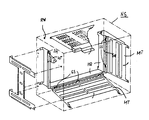
- the invention is illustrated in an exemplary embodiment explained in more detail in which the outer boundary areas of the low-voltage control box only through dash-dotted lines are indicated.
- the low-voltage switch box NS is U-shaped designed holding frame HR provided on the inside External boundary area RW, for example on the rear wall of the low-voltage switch box NS, is detachably attached. Furthermore, it can be seen that the holding frame HR in the the leg areas SH facing away from the fastening side Holding frame HR at least two hinge slots assigned to each other SS for hanging the respective MT assembly board contains.
- the mounting panels MT can be inside the hinge slots SS after they indicated by loosening their Screw connections from the corresponding outer boundary area - Rear or side wall of the low-voltage switch box NS - are separated so that they can be swiveled in can be removed directly from the hinge slots SS.
- the assembly boards MT with support rails can be equipped, which the installation of facilities of various Allow designs.
- the subsequent installation of the individual Devices in the corresponding low-voltage switch boxes NS can be simplified in such a way that the Assembly boards MT by loosening their screw connections from the Rear or side walls pivoted towards the holding frame HR and thus the freedom to accommodate the Wiring freely accessible for the individual facilities is made.
- On special protective measures for those in the Insufficient wiring space can be arranged be dispensed with that the assembly boards MT in their outer contours appropriately rounded or with bent edges are secured.
Landscapes
- Engineering & Computer Science (AREA)
- Power Engineering (AREA)
- Patch Boards (AREA)
- Driving Mechanisms And Operating Circuits Of Arc-Extinguishing High-Tension Switches (AREA)
- Switch Cases, Indication, And Locking (AREA)
Description
Die der Erfindung zugrundeliegende Aufgabe besteht darin, für die eingangs definierten Niederspannungs-Schaltkästen eine konstruktive Lösung zur Aufnahme der einzelnen Einrichtungen anzugeben, bei der der einsatzbedingte Mehraufwand hinsichtlich der Montage der einzelnen Einrichtungen sowie auch deren Verdrahtung untereinander auf ein Minimum begrenzt werden kann, ohne jedoch Einschränkungen hinsichtlich der möglichen Vielfalt zum Nachrüsten von zusätzlichen Einrichtungen hinnehmen zu müssen. Erfindungsgemäß wird dies erreicht durch die Merkmale
Claims (2)
- Niederspannungs-Schaltkasten zur Aufnahme und Einbau von Schutz-, Melde- und Steuerungstechnik-Einrichtungen, wobei die einzelnen Einrichtungen anlagenindividuell zusammengestellt und durch örtlich und/oder zeitlich voneinander einzubringende Verdrahtungen miteinander verknüpfbar sind, gekennzeichnet durch die Merkmale1.1 der Niederspannungs-Schaltkasten (NS) weist in mindestens einem innenliegenden Außenbegrenzungsbereich (RW) einen für die Verdrahrung raumbildenden einseitig offenen U-förmigen Halterahmen (HR) auf, der lösbar am innenliegenden Außenbegrenzungsbereich (RW) befestigt ist,1.2 der Halterahmen (HR) enthält in den der Befestigungsseite abgewandten Schenkelbereichen (SH) jeweils mindestens zwei einander zugeordnete Scharnierschlitze (SS) zum Einhängen einer Montagetafel (MT),1.3 die Montagetafeln (MT) stehen mit den Scharnierschlitzen (SS) schwenkbar und/oder entnehmbar in Eingriff und sind mit dem jeweils angrenzenden Außenbegrenzungsbereich (RW) derart lösbar verbunden, daß die Montagetafeln (MT) im Schwenkbereich jeweils im Winkel größer 90° zur Ebene der Scharnierschlitze (SS) angeordnet sind.
- Niederspannungs-Schaltkasten nach Anspruch 1,
gekennzeichnet durch das Merkmal2.1 die Montagetafeln (MT) sind zur Aufnahme der Einrichtungen mit Tragschienen unterschiedlicher Konturen bestückt.
Applications Claiming Priority (2)
| Application Number | Priority Date | Filing Date | Title |
|---|---|---|---|
| DE9404899U | 1994-03-18 | ||
| DE9404899U DE9404899U1 (de) | 1994-03-18 | 1994-03-18 | Niederspannungs-Schaltkasten mit Verdrahtungsfreiraum |
Publications (2)
| Publication Number | Publication Date |
|---|---|
| EP0673096A1 EP0673096A1 (de) | 1995-09-20 |
| EP0673096B1 true EP0673096B1 (de) | 1998-09-02 |
Family
ID=6906374
Family Applications (1)
| Application Number | Title | Priority Date | Filing Date |
|---|---|---|---|
| EP95250051A Expired - Lifetime EP0673096B1 (de) | 1994-03-18 | 1995-03-02 | Niederspannungs-Schaltkasten mit Verdrahtungsfreiraum |
Country Status (3)
| Country | Link |
|---|---|
| EP (1) | EP0673096B1 (de) |
| DE (2) | DE9404899U1 (de) |
| FI (1) | FI951214L (de) |
Families Citing this family (1)
| Publication number | Priority date | Publication date | Assignee | Title |
|---|---|---|---|---|
| AT923U1 (de) * | 1995-09-25 | 1996-07-25 | Felten & Guilleaume Ag Oester | Verbindungselement zum befestigen von tragelementen |
Family Cites Families (5)
| Publication number | Priority date | Publication date | Assignee | Title |
|---|---|---|---|---|
| DE1465775A1 (de) * | 1964-03-17 | 1969-11-13 | Kloeckner Moeller Elek Zitaets | Schaltschrank |
| DE7334075U (de) * | 1973-09-20 | 1978-06-08 | Rittal-Werk, Rudolf Loh Kg, 6341 Rittershausen | Montageplatte zur Befestigung von Bauteilen elektrischer Schaltungen für die Verwendung in elektrischen Schaltschränken u.dgl |
| DE8418270U1 (de) * | 1984-06-16 | 1984-09-13 | Rittal-Werk Rudolf Loh Gmbh & Co Kg, 6348 Herborn | Schaltschrank mit Montageplatte |
| DE9010522U1 (de) * | 1990-07-12 | 1990-09-13 | Quante AG, 5600 Wuppertal | Verteilerkasten für die Adern von Fernsprech-, Signal- oder Steuerkabeln |
| DE9202815U1 (de) * | 1992-03-04 | 1993-07-01 | Klöckner-Moeller GmbH, 5300 Bonn | Vorrichtung zur Befestigung von Schaltgeräten |
-
1994
- 1994-03-18 DE DE9404899U patent/DE9404899U1/de not_active Expired - Lifetime
-
1995
- 1995-03-02 EP EP95250051A patent/EP0673096B1/de not_active Expired - Lifetime
- 1995-03-02 DE DE59503399T patent/DE59503399D1/de not_active Expired - Fee Related
- 1995-03-15 FI FI951214A patent/FI951214L/fi unknown
Also Published As
| Publication number | Publication date |
|---|---|
| EP0673096A1 (de) | 1995-09-20 |
| FI951214A7 (fi) | 1995-09-19 |
| DE9404899U1 (de) | 1994-05-19 |
| DE59503399D1 (de) | 1998-10-08 |
| FI951214L (fi) | 1995-09-19 |
| FI951214A0 (fi) | 1995-03-15 |
Similar Documents
| Publication | Publication Date | Title |
|---|---|---|
| EP0939985A1 (de) | Bausatz für ein rahmengestell mit eckverbindung für die vertikalen rahmenprofile | |
| DE2145453A1 (de) | Tisch mit einer Anordnung zum Aufnehmen von Geräteanschlußkabeln | |
| DE10057122A1 (de) | Kabelkanalsystem mit getrennten Leitungen für Stromleiter und Datenübertragungsleiter | |
| EP1087482B1 (de) | Gehäusesystem | |
| DE4107228C2 (de) | ||
| DE4340255C2 (de) | Hängeschrank mit Befestigungsvorrichtung | |
| DE3300066A1 (de) | Schaltschrank | |
| DE3441446A1 (de) | Schalttafel nach dem baukastensystem | |
| DE19818603A1 (de) | Rahmenschenkel für ein Rahmengestell eines Schaltschrankes | |
| EP0673096A1 (de) | Niederspannungs-Schaltkasten mit Verdrahtungsfreiraum | |
| DE8915226U1 (de) | Kabelkanal | |
| DE29818507U1 (de) | Verteilerschrank | |
| DE9315131U1 (de) | Geräteschrank | |
| DE9211291U1 (de) | Verteiler für EMV abgeschirmte Schränke | |
| CH673552A5 (en) | Electrical or electronic appts housing - has two cooperative sections swung apart along one side edge to form double housing | |
| EP0626599B1 (de) | Verteilerschrank | |
| DE19726748C2 (de) | Kleingehäuse für den Wandanbau | |
| DE3312429C2 (de) | Kartenrahmen zur Aufnahme von Karten | |
| DE19948400C2 (de) | Schwenkadapter und Einrichtung der Telekommunikationstechnik mit einem Schwenkadapter | |
| DE29711262U1 (de) | Geräteschrank | |
| DE9318741U1 (de) | Spleisskassette für elektrische Leiter, insbesondere Lichtwellenleiter (LWL-Kabel), zum gekapselten Herstellen der Verbindungen und Verzweigungen von mehradrigen Kabeln | |
| DE29603161U1 (de) | Abdeckung für ein elektrisches Gehäuse | |
| DE3113003C2 (de) | Installationsverteiler für Wandeinbau | |
| DE69508031T2 (de) | Innenraumsystem für einen Schaltschrank und dafür geeigneter Komponentenmodul und Trägermodul | |
| DE2810927A1 (de) | Zaehlerschrank |
Legal Events
| Date | Code | Title | Description |
|---|---|---|---|
| PUAI | Public reference made under article 153(3) epc to a published international application that has entered the european phase |
Free format text: ORIGINAL CODE: 0009012 |
|
| AK | Designated contracting states |
Kind code of ref document: A1 Designated state(s): DE FR GB IT NL |
|
| 17P | Request for examination filed |
Effective date: 19960327 |
|
| GRAG | Despatch of communication of intention to grant |
Free format text: ORIGINAL CODE: EPIDOS AGRA |
|
| 17Q | First examination report despatched |
Effective date: 19971021 |
|
| GRAG | Despatch of communication of intention to grant |
Free format text: ORIGINAL CODE: EPIDOS AGRA |
|
| GRAH | Despatch of communication of intention to grant a patent |
Free format text: ORIGINAL CODE: EPIDOS IGRA |
|
| GRAH | Despatch of communication of intention to grant a patent |
Free format text: ORIGINAL CODE: EPIDOS IGRA |
|
| GRAA | (expected) grant |
Free format text: ORIGINAL CODE: 0009210 |
|
| AK | Designated contracting states |
Kind code of ref document: B1 Designated state(s): DE FR GB IT NL |
|
| PG25 | Lapsed in a contracting state [announced via postgrant information from national office to epo] |
Ref country code: NL Free format text: LAPSE BECAUSE OF FAILURE TO SUBMIT A TRANSLATION OF THE DESCRIPTION OR TO PAY THE FEE WITHIN THE PRESCRIBED TIME-LIMIT Effective date: 19980902 Ref country code: IT Free format text: LAPSE BECAUSE OF FAILURE TO SUBMIT A TRANSLATION OF THE DESCRIPTION OR TO PAY THE FEE WITHIN THE PRESCRIBED TIME-LIMIT;WARNING: LAPSES OF ITALIAN PATENTS WITH EFFECTIVE DATE BEFORE 2007 MAY HAVE OCCURRED AT ANY TIME BEFORE 2007. THE CORRECT EFFECTIVE DATE MAY BE DIFFERENT FROM THE ONE RECORDED. Effective date: 19980902 Ref country code: GB Free format text: LAPSE BECAUSE OF FAILURE TO SUBMIT A TRANSLATION OF THE DESCRIPTION OR TO PAY THE FEE WITHIN THE PRESCRIBED TIME-LIMIT Effective date: 19980902 Ref country code: FR Free format text: LAPSE BECAUSE OF FAILURE TO SUBMIT A TRANSLATION OF THE DESCRIPTION OR TO PAY THE FEE WITHIN THE PRESCRIBED TIME-LIMIT Effective date: 19980902 |
|
| REF | Corresponds to: |
Ref document number: 59503399 Country of ref document: DE Date of ref document: 19981008 |
|
| EN | Fr: translation not filed | ||
| NLV1 | Nl: lapsed or annulled due to failure to fulfill the requirements of art. 29p and 29m of the patents act | ||
| GBV | Gb: ep patent (uk) treated as always having been void in accordance with gb section 77(7)/1977 [no translation filed] |
Effective date: 19980902 |
|
| PLBE | No opposition filed within time limit |
Free format text: ORIGINAL CODE: 0009261 |
|
| STAA | Information on the status of an ep patent application or granted ep patent |
Free format text: STATUS: NO OPPOSITION FILED WITHIN TIME LIMIT |
|
| 26N | No opposition filed | ||
| PGFP | Annual fee paid to national office [announced via postgrant information from national office to epo] |
Ref country code: DE Payment date: 20020521 Year of fee payment: 8 |
|
| PG25 | Lapsed in a contracting state [announced via postgrant information from national office to epo] |
Ref country code: DE Free format text: LAPSE BECAUSE OF NON-PAYMENT OF DUE FEES Effective date: 20031001 |