EP0673553B1 - Ni-h2 batterie mit verbesserten temperatureigenschaften - Google Patents
Ni-h2 batterie mit verbesserten temperatureigenschaften Download PDFInfo
- Publication number
- EP0673553B1 EP0673553B1 EP19940903406 EP94903406A EP0673553B1 EP 0673553 B1 EP0673553 B1 EP 0673553B1 EP 19940903406 EP19940903406 EP 19940903406 EP 94903406 A EP94903406 A EP 94903406A EP 0673553 B1 EP0673553 B1 EP 0673553B1
- Authority
- EP
- European Patent Office
- Prior art keywords
- battery
- heat transfer
- compartments
- pressure vessel
- cell
- Prior art date
- Legal status (The legal status is an assumption and is not a legal conclusion. Google has not performed a legal analysis and makes no representation as to the accuracy of the status listed.)
- Expired - Lifetime
Links
Images



Classifications
-
- H—ELECTRICITY
- H01—ELECTRIC ELEMENTS
- H01M—PROCESSES OR MEANS, e.g. BATTERIES, FOR THE DIRECT CONVERSION OF CHEMICAL ENERGY INTO ELECTRICAL ENERGY
- H01M10/00—Secondary cells; Manufacture thereof
- H01M10/60—Heating or cooling; Temperature control
- H01M10/64—Heating or cooling; Temperature control characterised by the shape of the cells
-
- H—ELECTRICITY
- H01—ELECTRIC ELEMENTS
- H01M—PROCESSES OR MEANS, e.g. BATTERIES, FOR THE DIRECT CONVERSION OF CHEMICAL ENERGY INTO ELECTRICAL ENERGY
- H01M50/00—Constructional details or processes of manufacture of the non-active parts of electrochemical cells other than fuel cells, e.g. hybrid cells
- H01M50/10—Primary casings; Jackets or wrappings
- H01M50/138—Primary casings; Jackets or wrappings adapted for specific cells, e.g. electrochemical cells operating at high temperature
- H01M50/1385—Hybrid cells
-
- H—ELECTRICITY
- H01—ELECTRIC ELEMENTS
- H01M—PROCESSES OR MEANS, e.g. BATTERIES, FOR THE DIRECT CONVERSION OF CHEMICAL ENERGY INTO ELECTRICAL ENERGY
- H01M10/00—Secondary cells; Manufacture thereof
- H01M10/60—Heating or cooling; Temperature control
- H01M10/61—Types of temperature control
- H01M10/613—Cooling or keeping cold
-
- H—ELECTRICITY
- H01—ELECTRIC ELEMENTS
- H01M—PROCESSES OR MEANS, e.g. BATTERIES, FOR THE DIRECT CONVERSION OF CHEMICAL ENERGY INTO ELECTRICAL ENERGY
- H01M10/00—Secondary cells; Manufacture thereof
- H01M10/60—Heating or cooling; Temperature control
- H01M10/62—Heating or cooling; Temperature control specially adapted for specific applications
-
- H—ELECTRICITY
- H01—ELECTRIC ELEMENTS
- H01M—PROCESSES OR MEANS, e.g. BATTERIES, FOR THE DIRECT CONVERSION OF CHEMICAL ENERGY INTO ELECTRICAL ENERGY
- H01M10/00—Secondary cells; Manufacture thereof
- H01M10/60—Heating or cooling; Temperature control
- H01M10/65—Means for temperature control structurally associated with the cells
- H01M10/655—Solid structures for heat exchange or heat conduction
- H01M10/6554—Rods or plates
-
- H—ELECTRICITY
- H01—ELECTRIC ELEMENTS
- H01M—PROCESSES OR MEANS, e.g. BATTERIES, FOR THE DIRECT CONVERSION OF CHEMICAL ENERGY INTO ELECTRICAL ENERGY
- H01M10/00—Secondary cells; Manufacture thereof
- H01M10/60—Heating or cooling; Temperature control
- H01M10/65—Means for temperature control structurally associated with the cells
- H01M10/655—Solid structures for heat exchange or heat conduction
- H01M10/6554—Rods or plates
- H01M10/6555—Rods or plates arranged between the cells
-
- H—ELECTRICITY
- H01—ELECTRIC ELEMENTS
- H01M—PROCESSES OR MEANS, e.g. BATTERIES, FOR THE DIRECT CONVERSION OF CHEMICAL ENERGY INTO ELECTRICAL ENERGY
- H01M10/00—Secondary cells; Manufacture thereof
- H01M10/60—Heating or cooling; Temperature control
- H01M10/62—Heating or cooling; Temperature control specially adapted for specific applications
- H01M10/625—Vehicles
-
- H—ELECTRICITY
- H01—ELECTRIC ELEMENTS
- H01M—PROCESSES OR MEANS, e.g. BATTERIES, FOR THE DIRECT CONVERSION OF CHEMICAL ENERGY INTO ELECTRICAL ENERGY
- H01M10/00—Secondary cells; Manufacture thereof
- H01M10/60—Heating or cooling; Temperature control
- H01M10/64—Heating or cooling; Temperature control characterised by the shape of the cells
- H01M10/643—Cylindrical cells
-
- Y—GENERAL TAGGING OF NEW TECHNOLOGICAL DEVELOPMENTS; GENERAL TAGGING OF CROSS-SECTIONAL TECHNOLOGIES SPANNING OVER SEVERAL SECTIONS OF THE IPC; TECHNICAL SUBJECTS COVERED BY FORMER USPC CROSS-REFERENCE ART COLLECTIONS [XRACs] AND DIGESTS
- Y02—TECHNOLOGIES OR APPLICATIONS FOR MITIGATION OR ADAPTATION AGAINST CLIMATE CHANGE
- Y02E—REDUCTION OF GREENHOUSE GAS [GHG] EMISSIONS, RELATED TO ENERGY GENERATION, TRANSMISSION OR DISTRIBUTION
- Y02E60/00—Enabling technologies; Technologies with a potential or indirect contribution to GHG emissions mitigation
- Y02E60/10—Energy storage using batteries
Definitions
- the present invention relates to a common pressure vessel type Ni-H 2 storage battery, which may be used, for example, in powering satellites. More particularly, the invention relates to a common pressure vessel type Ni-H 2 storage battery having improved heat transfer properties between individual battery cells of the cell stack and the walls of the pressure vessel of the battery.
- Ni-H 2 batteries for satellite application employed individual pressure vessels for each cell in the battery.
- This type of Ni-H 2 battery is termed in the art a common pressure vessel type battery.
- Examples of common pressure vessel type Ni-H 2 batteries are described in the following publications: M. Earl et al., "Design and Development of an Aerospace CPV Ni/H 2 Battery", 24th Intersociety Energy Conversion Engineering Conference, Washington, D.C., August 1989, Proc. , Vol. 3, pp. 1395-1400; J.
- Ni-H 2 batteries considerable waste heat is generated during both charge and discharge portion of cycles.
- the individual cells were generally disposed inside of an insulating carrier.
- the thermal path between the heat generating portions of the cells and the wall of the pressure vessel was lengthwise through the battery cell stack components and then through the hydrogen gas of the battery to the adjacent wall of the pressure vessel.
- the thermal resistance between the individual cells and the pressure vessel was high, resulting in undesirable large temperature increases within the battery.
- a metal oxide hydrogen battery having heat transfer properties is known from US-A-5071652.
- the invention provides a battery including a pressure vessel, and a plurality of compartments disposed in side-by-side relation, each of the plurality of compartments including a heat transfer member having a fin portion and a flange portion extending longitudinally from the fin portion, the flange being in thermal contact with an inner wall of the pressure vessel, and a plurality of battery cells, at least one battery cell being disposed in each of the compartments and in thermal contact with adjacent fin portions of the heat transfer members ; and a cell spacer for maintaining adjacent heat transfer members of adjacent compartments a predetermined distance from one another.
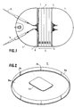
- a pressure vessel 5 of a preferred embodiment of a Ni-H 2 battery 1 of the invention is composed of a central cylindrical portion 4 capped at respective ends by end portions 2 and 3.
- a stack 6 of individual cylindrical compartments 20 disposed in side-by-side relation.
- the outer wall of the stack 6 of the cylindrical compartments 6 conforms to the shape of the central cylindrical portion 4 such that the outer wall of the stack is in thermal contact throughout its surface with the inner wall or surface of the central cylindrical portion 4 of the pressure vessel 5.
- each compartment 20 is composed of at least one battery cell 80, a heat transfer member 21, and a cell spacer 22 or an end plate 24 as shown in Fig. 5, for example.
- Figs. 2 and 3 illustrate the heat transfer member 21, which serves to transfer heat radially outward from the center of the battery to the inner wall of the pressure vessel 5 and thence into the surrounding atmosphere.
- the heat transfer member 21 is made of an aluminum or any other material having a high coefficient of thermal conductivity.
- the heat transfer member 21 includes a circular-shaped fin or body 21a having a cut-out 21d and a plurality of integral flanges 21b, which are separated from one another by a plurality of slits 21c.
- the flanges 21b extend longitudinally from the body 21a so as to form an "L-shape" fron a cross-sectional view of the heat transfer member 21.
- the flange 21b also forms the outside wall of the compartments 20, which is in thermal contact with the inner wall of the vessel 5.
- the flange 21b forms an obtuse angle ⁇ with the fin or body 21a of the heat transfer member 21 so as to insure a firm thermal contact between the flange and the inner wall of the vessel when inserted into the pressure vessel 5.
- the flanges 21b are deflected or bent inward and due to the flexibility of the flanges a radial force or biasing action will be exerted so as to maintain the segments in tight engagement with the inner wall of the vessel. This further ensures that as heat is extracted from within the vessel, the heat is sufficiently transferred to the vessel and subsequently to the surrounding atmosphere.
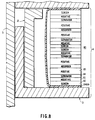
- each battery cell 80 is of generally semi-cylindrical or cylindrical shape and contains a repeating pattern of a gas diffusion screen 82, negative electrode 83, separator 84, and positive electrode 85.
- the arrangement and selection of the materials for these components is conventional and well within the skill of those familiar with this art.
- Each cell 80 is encased, for example, by a plastic bag 81, which electrically insulates the above-mentioned components from the fins 21 and spacers 22.
- the outer sides of the bag 81 are in intimate thermal contact with the fins 21a of the heat transfer member 21 on both sides of the cell so as to provide good thermal conduction between the cell 80, over its entire surface, and the heat transfer member 21.
- Fig. 6 illustrates the manner in which two generally semi-cylindrical battery cells 80 are situated within a heat transfer member 21, while Figs. 7 and 8 illustrate the encasing 81 of a battery cells 80 being in intimate thermal contact with adjacent fins 21a of adjacent heat transfer members 21.
- Figs. 7 and 8 also illustrate that the length of the flange 21b can vary relative to the width of a battery cell 80 and compartment 20. That is, the maximum length of a flange 21b will allow the end of the flange to come in contact with the adjacent heat transfer member 21.
- the length of the flange is less than the width of a compartment 20 or battery cell 80 so that the distance between adjacent heat transfer members 21 is determined by the spacers 22 as described in more detail below.
- the length of the flange must be of a certain length to provide a sufficient amount of surface contact between the flange and the inner wall of the vessel 5 so that a sufficient amount of heat can be withdrawn.
- the heat transfer member 21 of a first compartment is spaced from the heat transfer member 21 of an adjacent compartment by the cell spacer 22, which is generally of a ring-shape, as illustrated best in Fig. 4.
- First and second sides of the spacer come into contact with the fin or body 21a of adjacent heat transfer members 21.
- the cell spacers 22 are made of a rigid material (e.g., aluminum) such that the heat transfer members 21 are held stationary and at a relatively constant distance from one another.
- the spacers 22 also provide for the compartments 20 to remain at a relatively constant compression.
- the outer compartment 20 is spaced by an end cell spacer 24, which is composed of a ring-shaped portion 24a, similar to a cell spacer 22, and an integral circular body portion 24b with a cut-out 24c.
- each cell 80 has positive electrode terminals 86 and negative electrode terminals 87 which are respectively connected to the positive and negative electrodes 85 and 83 of the cell 80.
- the battery cells 80 of a compartment 20 can be connected to the battery cells of an adjacent compartment in series or in parallel to obtain the desired voltage output.
- the connection of adjacent terminals can be through the use of insulated interconnecting rods 36 and 46 which pass through center holes of the terminals 86 and 87, respectively, and through the cut-outs 21d of each of the heat transfer members and the cut-out 24c of the end cell spacer 24.
- the connection between battery cells and from the battery cells to external positive and negative electrodes 9, 10 can be similar to that which is described in the aforementioned patent application.
- first and second weld rings 7 secure the outer end portions 2 and 3, to the center cylindrical portion 4 and also hold the stack of compartments in place so as to prevent any shifting of the stack 6 of the compartments 20 in the axial direction.
- a wave spring 8 is disposed between the end cell spacer 24 of the stack and the weld ring 7. The wave spring 8 provides a preloading force on the stack of compartments in the axial direction thereof as well as absorbing any vibration or shock.
- Figs. 4 and 5 illustrate a exploded views of a stack 6.
- Fig. 4 illustrates two battery cells 80 placed within a heat transfer member 21.
- a cell spacer 22 abuts the fin portion 21a of the heat transfer member and around the outer periphery of the two battery cells 80.
- Fig. 5 illustrates the outer end compartment in which the ring-shaped portion 24b of the end cell spacer 24 is placed against the fin 21a of the heat transfer member 21 and around the outer periphery of the two battery cells 80.
- the circular body 24a of the end cell spacer 24 rests in contact with the bag 81 of the cell 80.
- the cut-out 24c allows the rods 36, 46 to pass therethrough.
- the heat transfer members 21 can be semi-circular in shape as well as the spacers.
- two stacks of compartments are assembled together to form a cylindrical shape. That is, each of the stack of compartments has an outer wall having the shape of a cylinder sliced lengthwise along a plane slightly offset from the longitudinal axis of the cylinder so that a small gap is provided between the two cell stacks.
- the two stacks of compartments once assembled are inserted into the vessel 5. Provisions for maintaining the gap between the two stacks are well known in the art, and a suitable example is illustrated and described in the aforementioned patent application.
- FIG. 11 Other embodiments include a heat transfer member of a "T-shape" such as that shown in Fig. 11.
- the heat transfer member includes a fin body 21a and a plurality of flanges 21b, 21b' extending longitudinally from both sides of the fin 21a.
- the flanges 21b, 21b' are separated by a plurality of slits 21c, 21c'.
Landscapes
- Chemical & Material Sciences (AREA)
- Chemical Kinetics & Catalysis (AREA)
- Electrochemistry (AREA)
- General Chemical & Material Sciences (AREA)
- Engineering & Computer Science (AREA)
- Manufacturing & Machinery (AREA)
- Secondary Cells (AREA)
- Hybrid Cells (AREA)
- Sealing Battery Cases Or Jackets (AREA)
Claims (6)
- Batterie, miteinem Druckgefäß (5) undeiner Vielzahl von Fächern (20), die Seite an Seite angeordnet sind, wobei jedes Fach folgende Bestandteile umfaßt:ein Wärmeübertragungselement (21), das einen Flossenteil (21a) und einen Flanschteil (21b) aufweist, der sich in Längsrichtung ausgehend vom Flossenteil erstreckt, wobei der Flanschteil in thermischem Kontakt mit einer Innenwand des Druckgefäßes (5) steht,eine Vielzahl von Batteriezellen, wobei wenigstens eine Batteriezelle in jedem der Fächer (20) und in thermischem Kontakt mit benachbarten Flossenteilen (21a) der Wärmeübertragungselemente angeordnet ist, undeinen Zellenabstandshalter (22) der dazu dient, benachbarte Wärmeübertragungselemente (21) von benachbarten Fächern voneinander in einem vorbestimmten Abstand zu halten.
- Batterie nach Anspruch 1, bei der der Zellenraum ringförmig ist.
- Batterie nach Anspruch 1, die weiterhin erste und zweite Schweißringe (7) und eine Wellenfeder (8) umfaßt und bei der ein erstes äußeres Fach einen Endzellen-Abstandshalter (24) umfaßt, wobei sich der erste Schweißring mit einem Wärmeübertragungselement eines zweiten äußeren Faches in Berührung befindet und sich die Wellenfeder mit im Endzellen-Abstandshalter und dem ersten Schweißring in Kontakt steht, um eine Vorspannungskraft auf den Stapel von Fächern auszuüben.
- Batterie nach Anspruch 1, bei der die Länge des Flanschteils des Wärmeübertragungselementes kleiner ist als die Breite der Batteriezelle.
- Batterie nach Anspruch 1, bei der die Länge des Flanschteils des Wärmeübertragungselementes die gleiche ist wie die Breite der Battenezelle.
- Batterie nach Anspruch 1, bei der der Flanschteil (21b) einen stumpfen Winkel mit dem Flossenteil (21a) bildet.
Applications Claiming Priority (3)
| Application Number | Priority Date | Filing Date | Title |
|---|---|---|---|
| US07/988,670 US5354630A (en) | 1992-12-10 | 1992-12-10 | Ni-H2 battery having improved thermal properties |
| US988670 | 1992-12-10 | ||
| PCT/US1993/011707 WO1994014206A1 (en) | 1992-12-10 | 1993-12-08 | Ni-h2 battery having improved thermal properties |
Publications (3)
| Publication Number | Publication Date |
|---|---|
| EP0673553A1 EP0673553A1 (de) | 1995-09-27 |
| EP0673553A4 EP0673553A4 (de) | 1996-06-26 |
| EP0673553B1 true EP0673553B1 (de) | 2001-02-21 |
Family
ID=25534383
Family Applications (1)
| Application Number | Title | Priority Date | Filing Date |
|---|---|---|---|
| EP19940903406 Expired - Lifetime EP0673553B1 (de) | 1992-12-10 | 1993-12-08 | Ni-h2 batterie mit verbesserten temperatureigenschaften |
Country Status (7)
| Country | Link |
|---|---|
| US (1) | US5354630A (de) |
| EP (1) | EP0673553B1 (de) |
| JP (1) | JP2979344B2 (de) |
| AT (1) | ATE199292T1 (de) |
| CA (1) | CA2151508C (de) |
| DE (1) | DE69329948D1 (de) |
| WO (1) | WO1994014206A1 (de) |
Cited By (20)
| Publication number | Priority date | Publication date | Assignee | Title |
|---|---|---|---|---|
| US7794868B2 (en) | 2005-12-02 | 2010-09-14 | Lg Chem, Ltd. | Battery module of high cooling efficiency |
| US7879485B2 (en) | 2005-04-20 | 2011-02-01 | Lg Chem, Ltd. | Housing member for battery module |
| US7883793B2 (en) | 2008-06-30 | 2011-02-08 | Lg Chem, Ltd. | Battery module having battery cell assemblies with alignment-coupling features |
| US8288031B1 (en) | 2011-03-28 | 2012-10-16 | Lg Chem, Ltd. | Battery disconnect unit and method of assembling the battery disconnect unit |
| US8353315B2 (en) | 2010-08-23 | 2013-01-15 | Lg Chem, Ltd. | End cap |
| US8426050B2 (en) | 2008-06-30 | 2013-04-23 | Lg Chem, Ltd. | Battery module having cooling manifold and method for cooling battery module |
| US8469404B2 (en) | 2010-08-23 | 2013-06-25 | Lg Chem, Ltd. | Connecting assembly |
| US8486552B2 (en) | 2008-06-30 | 2013-07-16 | Lg Chem, Ltd. | Battery module having cooling manifold with ported screws and method for cooling the battery module |
| US8628872B2 (en) | 2008-01-18 | 2014-01-14 | Lg Chem, Ltd. | Battery cell assembly and method for assembling the battery cell assembly |
| US8663828B2 (en) | 2009-04-30 | 2014-03-04 | Lg Chem, Ltd. | Battery systems, battery module, and method for cooling the battery module |
| US8662153B2 (en) | 2010-10-04 | 2014-03-04 | Lg Chem, Ltd. | Battery cell assembly, heat exchanger, and method for manufacturing the heat exchanger |
| US8663829B2 (en) | 2009-04-30 | 2014-03-04 | Lg Chem, Ltd. | Battery systems, battery modules, and method for cooling a battery module |
| US8758922B2 (en) | 2010-08-23 | 2014-06-24 | Lg Chem, Ltd. | Battery system and manifold assembly with two manifold members removably coupled together |
| US8852778B2 (en) | 2009-04-30 | 2014-10-07 | Lg Chem, Ltd. | Battery systems, battery modules, and method for cooling a battery module |
| US8920956B2 (en) | 2010-08-23 | 2014-12-30 | Lg Chem, Ltd. | Battery system and manifold assembly having a manifold member and a connecting fitting |
| US9005799B2 (en) | 2010-08-25 | 2015-04-14 | Lg Chem, Ltd. | Battery module and methods for bonding cell terminals of battery cells together |
| US9147916B2 (en) | 2010-04-17 | 2015-09-29 | Lg Chem, Ltd. | Battery cell assemblies |
| US9178192B2 (en) | 2011-05-13 | 2015-11-03 | Lg Chem, Ltd. | Battery module and method for manufacturing the battery module |
| US9337456B2 (en) | 2009-04-20 | 2016-05-10 | Lg Chem, Ltd. | Frame member, frame assembly and battery cell assembly made therefrom and methods of making the same |
| US9496544B2 (en) | 2011-07-28 | 2016-11-15 | Lg Chem. Ltd. | Battery modules having interconnect members with vibration dampening portions |
Families Citing this family (30)
| Publication number | Priority date | Publication date | Assignee | Title |
|---|---|---|---|---|
| US5821009A (en) * | 1997-03-03 | 1998-10-13 | Space Systems/Loral, Inc. | Fault tolerant bipolar gas electrode design for a rechargeable battery |
| US5952815A (en) * | 1997-07-25 | 1999-09-14 | Minnesota Mining & Manufacturing Co. | Equalizer system and method for series connected energy storing devices |
| US6146778A (en) | 1997-07-25 | 2000-11-14 | 3M Innovative Properties Company | Solid-state energy storage module employing integrated interconnect board |
| US6117584A (en) * | 1997-07-25 | 2000-09-12 | 3M Innovative Properties Company | Thermal conductor for high-energy electrochemical cells |
| US6087036A (en) * | 1997-07-25 | 2000-07-11 | 3M Innovative Properties Company | Thermal management system and method for a solid-state energy storing device |
| US6120930A (en) | 1997-07-25 | 2000-09-19 | 3M Innovative Properties Corporation | Rechargeable thin-film electrochemical generator |
| US6104967A (en) * | 1997-07-25 | 2000-08-15 | 3M Innovative Properties Company | Fault-tolerant battery system employing intra-battery network architecture |
| US6046514A (en) * | 1997-07-25 | 2000-04-04 | 3M Innovative Properties Company | Bypass apparatus and method for series connected energy storage devices |
| US6100702A (en) * | 1997-07-25 | 2000-08-08 | 3M Innovative Properties Company | In-situ fault detection apparatus and method for an encased energy storing device |
| US6099986A (en) | 1997-07-25 | 2000-08-08 | 3M Innovative Properties Company | In-situ short circuit protection system and method for high-energy electrochemical cells |
| US6235425B1 (en) | 1997-12-12 | 2001-05-22 | 3M Innovative Properties Company | Apparatus and method for treating a cathode material provided on a thin-film substrate |
| US6270920B1 (en) | 1998-03-19 | 2001-08-07 | Sanyo Electric Co., Ltd. | Battery module and container for battery module |
| US6821671B2 (en) * | 2002-03-01 | 2004-11-23 | Lg Chem, Ltd. | Method and apparatus for cooling and positioning prismatic battery cells |
| US7531270B2 (en) | 2006-10-13 | 2009-05-12 | Enerdel, Inc. | Battery pack with integral cooling and bussing devices |
| US20080193830A1 (en) * | 2006-10-13 | 2008-08-14 | Enerdel, Inc. | Battery assembly with temperature control device |
| DK2518790T3 (en) * | 2007-02-12 | 2015-03-23 | Randy Ogg | Stacked structures for electrochemical batteries |
| JP2011503800A (ja) | 2007-11-07 | 2011-01-27 | エナーデル、インク | 温度制御装置を有する電池アセンブリ |
| US8883342B2 (en) * | 2007-12-05 | 2014-11-11 | Enerdel, Inc. | Battery assembly with temperature control device |
| WO2009140199A2 (en) * | 2008-05-10 | 2009-11-19 | Enerdel, Inc. | Battery assembly |
| RU2366041C1 (ru) * | 2008-06-04 | 2009-08-27 | Открытое акционерное общество "Информационные спутниковые системы" им. академика М.Ф. Решетнева" | Способ эксплуатации никель-водородной аккумуляторной батареи и аккумуляторная батарея для его реализации |
| US8815429B2 (en) | 2009-01-12 | 2014-08-26 | A123 Systems Llc | Busbar supports and methods of their use for battery systems |
| WO2011069162A1 (en) | 2009-12-04 | 2011-06-09 | A123 Systems, Inc. | Battery with integrated power management system and scalable battery cutoff component |
| CN203398243U (zh) | 2010-05-21 | 2014-01-15 | 格拉弗技术国际控股有限公司 | 用于具有相对主表面的电池单元的热管理组件 |
| US8795872B2 (en) | 2010-07-26 | 2014-08-05 | Enerdel, Inc. | Battery cell system with interconnected frames |
| CN103314478B (zh) * | 2011-01-26 | 2016-02-03 | 株式会社Lg化学 | 具有提高的组装效率的冷却构件和采用该冷却构件的电池模块 |
| JP6610272B2 (ja) * | 2016-01-08 | 2019-11-27 | 株式会社豊田自動織機 | 電池モジュール |
| US10873111B2 (en) | 2016-08-09 | 2020-12-22 | Wisk Aero Llc | Battery with compression and prevention of thermal runaway propagation features |
| US10756398B2 (en) | 2018-06-22 | 2020-08-25 | Wisk Aero Llc | Capacitance reducing battery submodule with thermal runaway propagation prevention and containment features |
| US10593920B2 (en) | 2018-08-13 | 2020-03-17 | Wisk Aero Llc | Capacitance reduction in battery systems |
| US20240363927A1 (en) * | 2023-04-25 | 2024-10-31 | Ford Global Technologies, Llc | Battery pack thermal energy management assembly and thermal energy management method |
Family Cites Families (16)
| Publication number | Priority date | Publication date | Assignee | Title |
|---|---|---|---|---|
| US4038461A (en) * | 1976-01-28 | 1977-07-26 | The United States Of America As Represented By The Secretary Of The Air Force | Electrochemical cell having balanced distribution of oxygen and electrolyte |
| US4098962A (en) * | 1977-04-14 | 1978-07-04 | Yardney Electric Corporation | Metal-hydrogen secondary battery system |
| US4107402A (en) * | 1977-09-22 | 1978-08-15 | Globe-Union Inc. | Battery and battery container having air-flow passages therethrough |
| US4324845A (en) * | 1980-06-30 | 1982-04-13 | Communications Satellite Corp. | Metal-oxide-hydrogen cell with variable conductant heat pipe |
| US4327158A (en) * | 1980-08-15 | 1982-04-27 | Eic Laboratories, Inc. | Metal/gas battery |
| US4477540A (en) * | 1983-10-03 | 1984-10-16 | Eagle-Picher Industries, Inc. | Metal-gas cell with electrolyte reservoir |
| US4567119A (en) * | 1984-03-12 | 1986-01-28 | Hughes Aircraft Company | Nickel-hydrogen bipolar battery |
| US4546054A (en) * | 1985-02-22 | 1985-10-08 | Eagle-Picher Industries, Inc. | Support assembly for cells of a secondary battery |
| DE3737336C1 (de) * | 1987-11-04 | 1988-11-17 | Deutsche Automobilgesellsch | Schweiss- und Stuetzring und seine Verwendung |
| US4950564A (en) * | 1988-05-02 | 1990-08-21 | Gates Energy Products, Inc. | Metal gas cell |
| US4957830A (en) * | 1989-04-07 | 1990-09-18 | Globe-Union Inc. | Rechargeable metal oxide-hydrogen battery |
| US4923769A (en) * | 1989-04-07 | 1990-05-08 | Globe-Union Inc. | Pressure vessel construction for a metal oxide-hydrogen battery |
| DE3923308C1 (de) * | 1989-07-14 | 1990-12-20 | Deutsche Automobilgesellschaft Mbh, 3000 Hannover, De | |
| CA2038354A1 (en) * | 1990-03-30 | 1991-10-01 | William H. Kelly | Ni-h2 battery having improved thermal properties |
| US5071652A (en) * | 1990-12-11 | 1991-12-10 | Globe-Union Inc. | Metal oxide hydrogen battery having improved heat transfer properties |
| US5168017A (en) * | 1991-10-28 | 1992-12-01 | Globe-Union Inc. | Metal oxide-hydrogen battery having rectangular modules in a cylindrical pressure vessel |
-
1992
- 1992-12-10 US US07/988,670 patent/US5354630A/en not_active Expired - Lifetime
-
1993
- 1993-12-08 EP EP19940903406 patent/EP0673553B1/de not_active Expired - Lifetime
- 1993-12-08 DE DE69329948T patent/DE69329948D1/de not_active Expired - Lifetime
- 1993-12-08 CA CA 2151508 patent/CA2151508C/en not_active Expired - Fee Related
- 1993-12-08 JP JP51424894A patent/JP2979344B2/ja not_active Expired - Fee Related
- 1993-12-08 WO PCT/US1993/011707 patent/WO1994014206A1/en not_active Ceased
- 1993-12-08 AT AT94903406T patent/ATE199292T1/de active
Cited By (21)
| Publication number | Priority date | Publication date | Assignee | Title |
|---|---|---|---|---|
| US7879485B2 (en) | 2005-04-20 | 2011-02-01 | Lg Chem, Ltd. | Housing member for battery module |
| US7955726B2 (en) | 2005-12-02 | 2011-06-07 | Lg Chem, Ltd. | Battery module of high cooling efficiency |
| US7794868B2 (en) | 2005-12-02 | 2010-09-14 | Lg Chem, Ltd. | Battery module of high cooling efficiency |
| US8628872B2 (en) | 2008-01-18 | 2014-01-14 | Lg Chem, Ltd. | Battery cell assembly and method for assembling the battery cell assembly |
| US7883793B2 (en) | 2008-06-30 | 2011-02-08 | Lg Chem, Ltd. | Battery module having battery cell assemblies with alignment-coupling features |
| US8426050B2 (en) | 2008-06-30 | 2013-04-23 | Lg Chem, Ltd. | Battery module having cooling manifold and method for cooling battery module |
| US8486552B2 (en) | 2008-06-30 | 2013-07-16 | Lg Chem, Ltd. | Battery module having cooling manifold with ported screws and method for cooling the battery module |
| US9337456B2 (en) | 2009-04-20 | 2016-05-10 | Lg Chem, Ltd. | Frame member, frame assembly and battery cell assembly made therefrom and methods of making the same |
| US8663829B2 (en) | 2009-04-30 | 2014-03-04 | Lg Chem, Ltd. | Battery systems, battery modules, and method for cooling a battery module |
| US8663828B2 (en) | 2009-04-30 | 2014-03-04 | Lg Chem, Ltd. | Battery systems, battery module, and method for cooling the battery module |
| US8852778B2 (en) | 2009-04-30 | 2014-10-07 | Lg Chem, Ltd. | Battery systems, battery modules, and method for cooling a battery module |
| US9147916B2 (en) | 2010-04-17 | 2015-09-29 | Lg Chem, Ltd. | Battery cell assemblies |
| US8353315B2 (en) | 2010-08-23 | 2013-01-15 | Lg Chem, Ltd. | End cap |
| US8758922B2 (en) | 2010-08-23 | 2014-06-24 | Lg Chem, Ltd. | Battery system and manifold assembly with two manifold members removably coupled together |
| US8920956B2 (en) | 2010-08-23 | 2014-12-30 | Lg Chem, Ltd. | Battery system and manifold assembly having a manifold member and a connecting fitting |
| US8469404B2 (en) | 2010-08-23 | 2013-06-25 | Lg Chem, Ltd. | Connecting assembly |
| US9005799B2 (en) | 2010-08-25 | 2015-04-14 | Lg Chem, Ltd. | Battery module and methods for bonding cell terminals of battery cells together |
| US8662153B2 (en) | 2010-10-04 | 2014-03-04 | Lg Chem, Ltd. | Battery cell assembly, heat exchanger, and method for manufacturing the heat exchanger |
| US8288031B1 (en) | 2011-03-28 | 2012-10-16 | Lg Chem, Ltd. | Battery disconnect unit and method of assembling the battery disconnect unit |
| US9178192B2 (en) | 2011-05-13 | 2015-11-03 | Lg Chem, Ltd. | Battery module and method for manufacturing the battery module |
| US9496544B2 (en) | 2011-07-28 | 2016-11-15 | Lg Chem. Ltd. | Battery modules having interconnect members with vibration dampening portions |
Also Published As
| Publication number | Publication date |
|---|---|
| CA2151508A1 (en) | 1994-06-23 |
| EP0673553A1 (de) | 1995-09-27 |
| US5354630A (en) | 1994-10-11 |
| JP2979344B2 (ja) | 1999-11-15 |
| JPH08506205A (ja) | 1996-07-02 |
| ATE199292T1 (de) | 2001-03-15 |
| EP0673553A4 (de) | 1996-06-26 |
| CA2151508C (en) | 1999-01-26 |
| WO1994014206A1 (en) | 1994-06-23 |
| DE69329948D1 (de) | 2001-03-29 |
Similar Documents
| Publication | Publication Date | Title |
|---|---|---|
| US5354630A (en) | Ni-H2 battery having improved thermal properties | |
| JP3059276B2 (ja) | 酸化金属水素バッテリ | |
| US5503947A (en) | Ni-H2 battery having improved thermal properties | |
| US4324845A (en) | Metal-oxide-hydrogen cell with variable conductant heat pipe | |
| US4957830A (en) | Rechargeable metal oxide-hydrogen battery | |
| US5162171A (en) | Metal oxide-hydrogen battery having modules extending longitudinally of the pressure vessel | |
| US6020084A (en) | Electrochemical cell design with a hollow core | |
| US6146786A (en) | Electrochemical storage cell having a central core providing mechanical, thermal, and electrical functions | |
| WO1999005743A1 (en) | Pressure system and method for rechargeable thin-film electrochemical cells | |
| JPH04349364A (ja) | プレーナ型ナトリウム硫黄蓄電池 | |
| US4517264A (en) | Lightweight metal-hydrogen cell with improved plate stack supporting means | |
| US4546054A (en) | Support assembly for cells of a secondary battery | |
| US4000350A (en) | Battery design | |
| US5422196A (en) | Pressure vessel for pressurized secondary cells and batteries | |
| US3548222A (en) | Thermionic power generation apparatus | |
| GB2261544A (en) | Metal oxide-hydrogen battery having rectangular modules in a cylindrical pressure vessel | |
| JPH0722003A (ja) | 二次電池収納容器 | |
| US5389460A (en) | Vibration-resistant battery having individually supported storage cells | |
| US5002842A (en) | End plate for a metal gas cell | |
| Earl et al. | Design and development of an aerospace CPV Ni/H/sub 2/battery | |
| JPS62150649A (ja) | 密閉形鉛蓄電池 |
Legal Events
| Date | Code | Title | Description |
|---|---|---|---|
| PUAI | Public reference made under article 153(3) epc to a published international application that has entered the european phase |
Free format text: ORIGINAL CODE: 0009012 |
|
| 17P | Request for examination filed |
Effective date: 19950606 |
|
| AK | Designated contracting states |
Kind code of ref document: A1 Designated state(s): AT DE FR GB |
|
| A4 | Supplementary search report drawn up and despatched |
Effective date: 19960508 |
|
| AK | Designated contracting states |
Kind code of ref document: A4 Designated state(s): AT DE FR GB |
|
| GRAG | Despatch of communication of intention to grant |
Free format text: ORIGINAL CODE: EPIDOS AGRA |
|
| RTI1 | Title (correction) |
Free format text: NI-H2 BATTERY HAVING IMPROVED THERMAL PROPERTIES |
|
| 17Q | First examination report despatched |
Effective date: 20000217 |
|
| GRAG | Despatch of communication of intention to grant |
Free format text: ORIGINAL CODE: EPIDOS AGRA |
|
| GRAH | Despatch of communication of intention to grant a patent |
Free format text: ORIGINAL CODE: EPIDOS IGRA |
|
| GRAH | Despatch of communication of intention to grant a patent |
Free format text: ORIGINAL CODE: EPIDOS IGRA |
|
| GRAA | (expected) grant |
Free format text: ORIGINAL CODE: 0009210 |
|
| AK | Designated contracting states |
Kind code of ref document: B1 Designated state(s): AT DE FR GB |
|
| PG25 | Lapsed in a contracting state [announced via postgrant information from national office to epo] |
Ref country code: AT Free format text: LAPSE BECAUSE OF FAILURE TO SUBMIT A TRANSLATION OF THE DESCRIPTION OR TO PAY THE FEE WITHIN THE PRESCRIBED TIME-LIMIT Effective date: 20010221 |
|
| REF | Corresponds to: |
Ref document number: 199292 Country of ref document: AT Date of ref document: 20010315 Kind code of ref document: T |
|
| REF | Corresponds to: |
Ref document number: 69329948 Country of ref document: DE Date of ref document: 20010329 |
|
| PG25 | Lapsed in a contracting state [announced via postgrant information from national office to epo] |
Ref country code: DE Free format text: LAPSE BECAUSE OF FAILURE TO SUBMIT A TRANSLATION OF THE DESCRIPTION OR TO PAY THE FEE WITHIN THE PRESCRIBED TIME-LIMIT Effective date: 20010522 |
|
| ET | Fr: translation filed | ||
| PG25 | Lapsed in a contracting state [announced via postgrant information from national office to epo] |
Ref country code: GB Free format text: LAPSE BECAUSE OF NON-PAYMENT OF DUE FEES Effective date: 20011208 |
|
| PLBE | No opposition filed within time limit |
Free format text: ORIGINAL CODE: 0009261 |
|
| STAA | Information on the status of an ep patent application or granted ep patent |
Free format text: STATUS: NO OPPOSITION FILED WITHIN TIME LIMIT |
|
| REG | Reference to a national code |
Ref country code: GB Ref legal event code: IF02 |
|
| 26N | No opposition filed | ||
| GBPC | Gb: european patent ceased through non-payment of renewal fee |
Effective date: 20011208 |
|
| PGFP | Annual fee paid to national office [announced via postgrant information from national office to epo] |
Ref country code: FR Payment date: 20100106 Year of fee payment: 17 |
|
| REG | Reference to a national code |
Ref country code: FR Ref legal event code: ST Effective date: 20110831 |
|
| PG25 | Lapsed in a contracting state [announced via postgrant information from national office to epo] |
Ref country code: FR Free format text: LAPSE BECAUSE OF NON-PAYMENT OF DUE FEES Effective date: 20110103 |