EP0673564B1 - Vorrichtung zur konversion einer binären gleitkommazahl in einen binären logarithmus mit der basis 2 oder dessen umkehrung - Google Patents
Vorrichtung zur konversion einer binären gleitkommazahl in einen binären logarithmus mit der basis 2 oder dessen umkehrung Download PDFInfo
- Publication number
- EP0673564B1 EP0673564B1 EP94902160A EP94902160A EP0673564B1 EP 0673564 B1 EP0673564 B1 EP 0673564B1 EP 94902160 A EP94902160 A EP 94902160A EP 94902160 A EP94902160 A EP 94902160A EP 0673564 B1 EP0673564 B1 EP 0673564B1
- Authority
- EP
- European Patent Office
- Prior art keywords
- logarithm
- floating
- mantissa
- directed
- part circuit
- Prior art date
- Legal status (The legal status is an assumption and is not a legal conclusion. Google has not performed a legal analysis and makes no representation as to the accuracy of the status listed.)
- Expired - Lifetime
Links
Images


Classifications
-
- G—PHYSICS
- G06—COMPUTING OR CALCULATING; COUNTING
- G06F—ELECTRIC DIGITAL DATA PROCESSING
- G06F7/00—Methods or arrangements for processing data by operating upon the order or content of the data handled
- G06F7/38—Methods or arrangements for performing computations using exclusively denominational number representation, e.g. using binary, ternary, decimal representation
- G06F7/48—Methods or arrangements for performing computations using exclusively denominational number representation, e.g. using binary, ternary, decimal representation using non-contact-making devices, e.g. tube, solid state device; using unspecified devices
- G06F7/544—Methods or arrangements for performing computations using exclusively denominational number representation, e.g. using binary, ternary, decimal representation using non-contact-making devices, e.g. tube, solid state device; using unspecified devices for evaluating functions by calculation
- G06F7/556—Logarithmic or exponential functions
-
- H—ELECTRICITY
- H03—ELECTRONIC CIRCUITRY
- H03M—CODING; DECODING; CODE CONVERSION IN GENERAL
- H03M7/00—Conversion of a code where information is represented by a given sequence or number of digits to a code where the same, similar or subset of information is represented by a different sequence or number of digits
- H03M7/14—Conversion to or from non-weighted codes
- H03M7/24—Conversion to or from floating-point codes
Definitions
- the present invention concerns a device for conversion of a binary floating-point number into a binary fix-point 2-logarithm number or the opposite.
- a present trend in radar system design is to move the digital signal processing as close to the antenna as possible. There are two reasons for this. Firstly the system will be less sensitive for interfering signals (disturbances) and secondly digital circuits are cheaper than corresponding analog circuits.
- Digital signal processing for systems such as radar, radio and telephone require fairly high dynamic range, but can often tolerate a more limited relative accuracy.
- a method that reduces the number of bits used and in so doing is based on logarithmic conversion is therefore of interest.
- the main benefit of logarithmic conversion lies in the fact that multiplications and divisions are reduced to additions and subtractions, and powers and roots become simple shifts.
- the most common method to implement a logarithmic conversion is based on look-up tables.
- Read-Only Memories (ROM) can be used as tables, but most often they become large and introduce too large a delay for the systems in question.
- a binary floating-point number has the form
- the exponent is determined by the position of the Most Significant Bit (MSB) in the binary number.
- MSB Most Significant Bit
- the mantissa is the MSB followed by the remaining bits as the fractional part.
- the mantissa is 1.01110110 bin .
- a logarithm have the form an integer part, the characteristic, and a fractional part, the mantissa of the logarithm, whereby both the characteristic and the mantissa in the following calculations consist of a fixed number of bits.
- the known method of linear approximation is based on the resemblance between a binary floating-point number and a 2-logarithm in the binary fix-point format, cf. figure 1.
- the exponent of the floating point number and the integer part of the logarithm are equal.
- the fractional part of the mantissa of the floating-point number can be used as an approximation of the mantissa of the logarithm.
- the present invention is based on the latter method and means that it is corrected to reduce the error and, at a suitable choice of input system constants, distribute it on the whole evenly on both sides of the true value, which is what you wish. This is done by designing the invention according to the following independent claim. Further, the invention can, in an especially advantageous embodiment, be directly implemented on a digital VLSI-circuit.
- the saw-tooth function is then multiplied with coefficients C n in such a way that the sum of the additional part or parts and the original linear approximation is as close to the true value of the logarithm as one wishes.
- the accuracy of the approximation of the logarithm created in this way is determined by the number of additional parts in the form of saw-tooth functions that are used, as well as how well the coefficients are chosen.
- a great advantage with the present invention is that it can easily be transferred into hardware in the form of an Application Specific Integrated Circuit, an ASIC.
- This digital circuit becomes smaller (and less complicated) as well as faster and more precise than earlier known circuits for the same application.
- the construction can be made with the help of registers, XOR-gates, multipliers and adders.
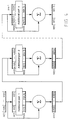
- the exponent and mantissa of the floating-point number are placed in a register, cf. figure 1.
- the exponent is guided from this to a register designed to store the improved approximation of the logarithm after the conversion and is stored there directly as the integer part of this approximation.
- the fractional part of the mantissa of the floating-point number is guided, both directly to an adder, and also to one or more part circuits forming additional parts 1, 2, 3, ... .
- To the first part circuit all the bits of the fractional part are guided, to the second part circuit bit number two and the following bits of the fractional part are guided, to the third part circuit bit number three and the following bits of the fractional part are guided and so forth.
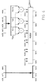
- figure 3 it is shown how several such additional parts are added in parallel while figure 4 shows an addition in series of the additional parts. Normally it is suitable to carry out the addition in parallel.
- part circuits cf. figure 5
- the outputs from the XOR-gates will then be multiplied with a suitable scale factor, the constants C 1 , C 2 , ..., so the error is minimized. This can, as is shown in figure 5, be done by a multiplication in a multiplier.
- the input signal and output signal of the processor were 11-bit and 8-bit respectively.
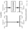
- Figure 8 shows a simplified flow chart of the implementation of the computations.
- the incoming signals I and Q are already in floating-point form.
- the exponent uses 4 bits and the mantissa (without sign) 7 bits.
- FLC the floating point value is converted into logarithmic form in accordance with the method of the invention.
- the squaring is performed as a simple shift in logarithmic form.
- LFC the logarithms are converted back to floating-point form, as the next computation step is an addition.
- the addition there is once again a conversion into logarithmic form in a FLC block, whereupon the square root is computed as a simple shift.
- Both the integer part and the fractional part of the logarithm output use 4 bits.
- the characteristic and mantissa of the logarithm are placed in a register, cf. figure 10.
- the characteristic, the integer part is guided from this to a register designed to store the floating-point number after the conversion and is stored there directly as its exponent.
- the mantissa of the logarithm is guided, cf. figure 11 and 12, both directly to an adder, and also to one or more part circuits forming additional parts 1, 2, 3, ... .
- To the first part circuit all the bits of the fractional part are guided, to the second part circuit bit number two and the following bits of the fractional part are guided, to the third part circuit bit number three and the following bits of the fractional part are guided and so forth.
- figure 11 it is shown how several such additional parts are added in parallel while figure 12 shows an addition in series of the additional parts. Normally it is suitable to carry out the addition in parallel.
- part circuits are identical to those that are used in the conversion from floating-point number into logarithm, cf. figure 5, and comprises a number of XOR-gates. To one of the inputs of these XOR-gates the most significant bit of the bits that are guided to each part circuit is guided and to the other input of each XOR-gate different following bits of the fractional part are guided, which means that the following bits are inverted when the most significant bit is 1 and are unchanged when this is 0.
- the outputs from the XOR-gates will then be multiplied with a suitable scale factor, the constants C 1 , C 2 , ..., so the error is minimized. Note that the constants in this case are negative. This can, as is shown in figure 5, be done by a multiplication in a multiplier.
- an initial one which is to be the integer one (the MSB of the binary number) of the resulting binary floating-point number, is added to the fractional part of the real logarithm or the improved approximation of it and the different additional parts (that have negative sign), at which permanent ones are put on the not connected inputs, also CIN (carry-in) is one.
- CIN carrier-in
- the result of the addition is guided to the register that stores the floating-point number after the conversion, where it forms the mantissa of the floating-point number.
- the negative sign of the constant is here obtained by using an inverter.
- this is shown by the inverter that is located in the connection for the most significant bit, the bit that is guided to every XOR-gate within a part circuit, when computing the different additional parts.
Landscapes
- Engineering & Computer Science (AREA)
- Theoretical Computer Science (AREA)
- General Physics & Mathematics (AREA)
- Physics & Mathematics (AREA)
- Mathematical Analysis (AREA)
- Pure & Applied Mathematics (AREA)
- Computational Mathematics (AREA)
- Computing Systems (AREA)
- Mathematical Optimization (AREA)
- General Engineering & Computer Science (AREA)
- Complex Calculations (AREA)
- Analogue/Digital Conversion (AREA)
- Compression, Expansion, Code Conversion, And Decoders (AREA)
Claims (13)
- Vorrichtung zur Konversion einer binären Gleitkommazahl in einen binären Logarithmus mit der Basis 2 durch lineare Approximation, dadurch gekennzeichnet, daß die Vorrichtung folgendes aufweist:ein Eingangsregister, in welchem die Gleitkommazahl gespeichert wird;ein Ausgangsregister für den berechneten Logarithmus;eine Vorrichtung, welche den Exponenten der Gleitkommazahl vom Eingangsregister zum Ausgangsregister, in welchem der Exponent direkt das charakteristische Merkmal des Logarithmus bildet, überträgt;eine Vorrichtung, welche die Stellen hinter dem Komma der Mantisse der Gleitkommazahl vom Eingangsregister zu einer Additionseinrichtung überträgt und zudem zu einem oder mehreren Teilgliedern, wobei jedes Teilglied basierend auf den Stellen hinter dem Komma der Mantisse einen zusätzlichen Bruchteil berechnet;eine Vorrichtung, die die zusätzlichen Bruchteile an die Additionseinrichtung überträgt;die Additionseinrichtung, welche die Stellen hinter dem Komma der Mantisse der Gleitkommazahl und die zusätzlichen Bruchteile addiert; undeine Vorrichtung, welche die Summe von der Additionseinrichtung zum Ausgangsregister, in welchem es die Stellen hinter dem Komma des Logarithmus mit der Basis 2 bildet, überträgt.
- Vorrichtung nach Anspruch 1, dadurch gekennzeichnet, daß der Übertrag auf die Additionseinrichtung auf Null gestellt ist.
- Vorrichtung nach Anspruch 1 oder 2, dadurch gekennzeichnet, daß alle Bits in den Stellen hinter dem Komma der Mantisse der Gleitkommazahl zum ersten Teilglied geleitet werden, das Bit mit der Zahl 2 und die folgenden zu dem möglicherweise bestehenden zweiten Teilglied geleitet werden, das Bit mit der Zahl 3 und die folgenden zu dem möglicherweise bestehenden dritten Teilglied geleitet werden, und so weiter.
- Vorrichtung nach Anspruch 3, dadurch gekennzeichnet, daß jedes Teilglied eine Anzahl von exklusiven ODER-Schaltungen aufweist, wobei die Anzahl der exklusiven ODER-Schaltungen um 1 geringer als die Bitanzahl ist, welche zu dem betreffenden Teilglied geleitet wird, das signifikanteste Bit der Bits, welche an jedes Teilglied geleitet werden, an den ersten Eingang aller exklusiven ODER-Schaltungen dieses Teilglieds geleitet wird und das zweite Bit zum zweiten Eingang der ersten exklusiven ODER-Schaltung dieses Teilglieds geleitet wird, das dritte Bit zum zweiten Eingang der zweiten exklusiven ODER-Schaltung dieses Teilglieds, das vierte Bit zum zweiten Eingang der dritten exklusiven ODER-Schaltung dieses Teilglieds, und so weiter.
- Vorrichtung zur Konversion eines binären Logarithmus mit der Basis 2 in eine binäre Gleitkommazahl durch lineare Approximation, dadurch gekennzeichnet, daß die Vorrichtung folgendes aufweist:ein Eingangsregister, in welchem der Logarithmus mit der Basis 2 gespeichert wird;ein Ausgangsregister für die berechnete Gleitkommazahl;eine Vorrichtung, welche das charakteristische Merkmal des Logarithmus vom Eingangsregister zum Ausgangsregister überträgt, wobei das charakteristische Merkmal im Ausgangsregister direkt den Exponenten der Gleitkommazahl bildet;eine Vorrichtung, welche die Mantisse des Logarithmus vom Eingangsregister zu einer Additionseinrichtung überträgt und zudem zu einem oder mehreren Teilgliedem, wobei jedes Teilglied basierend auf der Mantisse des Logarithmus einen zusätzlichen Bruchteil berechnet;eine Vorrichtung, die die zusätzlichen Bruchteile an die Additionseinrichtung überträgt;die Additionseinrichtung, welche die Mantisse des Logarithmus und die zusätzlichen Bruchteile zur Erzeugung der Stellen hinter dem Komma der Mantisse der Gleitkommazahl addiert und diese zu einer ganzen Zahl 1 addiert; undeine Vorrichtung, welche die Summe von der Additionseinrichtung zum Ausgangsregister, in welchem es die Mantisse der Gleitkommazahl bildet, überträgt.
- Vorrichtung nach Anspruch 5, dadurch gekennzeichnet, daß der Übertrag auf die Additionseinrichtung 1 beträgt.
- Vorrichtung nach Anspruch 5 oder 6, dadurch gekennzeichnet, daß alle Bits in der Mantisse des Logarithmus zum ersten Teilglied geleitet werden, das Bit mit der Zahl 2 und die folgenden zu dem möglicherweise bestehenden zweiten Teilglied geleitet werden, das Bit mit der Zahl 3 und die folgenden zu dem möglicherweise bestehenden dritten Teilglied geleitet werden, und so weiter.
- Vorrichtung nach Anspruch 7, dadurch gekennzeichnet, daß jedes Teilglied eine Anzahl von exklusiven ODER-Schaltungen aufweist, wobei die Anzahl der exklusiven ODER-Schaltungen um 1 geringer als die Bitanzahl ist, welche zu dem betreffenden Teilglied geleitet wird, das signifikanteste Bit der Bits, welche zu jedem Teilglied geleitet werden, so angeordnet ist, daß es zu einem Inverter geleitet wird und anschließend zu dem ersten Eingang von allen exklusiven ODER-Schaltungen dieses Teilglieds und das zweite Bit zu dem zweiten Eingang der ersten exklusiven ODER-Schaltung dieses Teilglieds geleitet wird, das dritte Bit zu dem zweiten Eingang der zweiten exklusiven ODER-Schaltung dieses Teilglieds, das vierte Bit zu dem zweiten Eingang der dritten exklusiven ODER-Schaltung dieses Teilglieds, und so weiter.
- Vorrichtung nach den Ansprüchen 4 oder 8, dadurch gekennzeichnet, daß die Ausgangssignale von den exklusiven ODER-Schaltungen mit einem geeigneten Skalierungsfaktor, den Konstanten C1, C2 usw. multipliziert werden.
- Vorrichtung nach einem der vorhergehenden Ansprüche, dadurch gekennzeichnet, daß die unterschiedlichen zusätzlichen Bruchteile so angeordnet sind, daß sie paralleladdiert werden.
- Vorrichtung nach einem der vorhergehenden Ansprüche, dadurch gekennzeichnet, daß die Vorrichtung so konstruiert ist, daß sie Konstanten verwendet, die gerade Potenzen von 2 sind, und weiter die Muliplikation mit Hilfe des Leitwegs durchführt.
- Vorrichtung nach Anspruch 11, dadurch gekennzeichnet, daß die Vorrichtung so angeordnet ist, daß sie nur ein Teilglied verwendet, welches nur einen zusätzlichen Bruchteil ergibt, weiter die Konstante 0,25dec=0.01bin verwendet, und die Muliplikation durch Addition des zusätzlichen Bruchteils, welcher zwei Stufen verschoben ist, zur Mantisse der Gleitkommazahl in der Additionseinrichtung durchführt.
- Vorrichtung nach einem der Ansprüche 11 oder 12, dadurch gekennzeichnet, daß sie als ein anwendungsspezifischer integrierter Schaltkreis ausgeführt ist.
Applications Claiming Priority (3)
| Application Number | Priority Date | Filing Date | Title |
|---|---|---|---|
| SE9203683A SE470542B (sv) | 1992-12-07 | 1992-12-07 | Anordning för omvandling av ett binärt flyttal till en 2- logaritm i binär form eller omvänt |
| SE9203683 | 1992-12-07 | ||
| PCT/SE1993/001039 WO1994014245A1 (en) | 1992-12-07 | 1993-12-02 | A device for conversion of a binary floating-point number into a binary 2-logarithm or the opposite |
Publications (2)
| Publication Number | Publication Date |
|---|---|
| EP0673564A1 EP0673564A1 (de) | 1995-09-27 |
| EP0673564B1 true EP0673564B1 (de) | 2000-03-29 |
Family
ID=20388052
Family Applications (1)
| Application Number | Title | Priority Date | Filing Date |
|---|---|---|---|
| EP94902160A Expired - Lifetime EP0673564B1 (de) | 1992-12-07 | 1993-12-02 | Vorrichtung zur konversion einer binären gleitkommazahl in einen binären logarithmus mit der basis 2 oder dessen umkehrung |
Country Status (5)
| Country | Link |
|---|---|
| EP (1) | EP0673564B1 (de) |
| JP (1) | JPH08504046A (de) |
| DE (1) | DE69328261T2 (de) |
| SE (1) | SE470542B (de) |
| WO (1) | WO1994014245A1 (de) |
Cited By (1)
| Publication number | Priority date | Publication date | Assignee | Title |
|---|---|---|---|---|
| CN103455302A (zh) * | 2012-05-31 | 2013-12-18 | 上海华虹集成电路有限责任公司 | 用硬件实现对数运算的电路 |
Families Citing this family (6)
| Publication number | Priority date | Publication date | Assignee | Title |
|---|---|---|---|---|
| SE502892C2 (sv) * | 1994-06-01 | 1996-02-12 | Foersvarets Forskningsanstalt | Anordning för omvandling av ett binärt flyttal till en 2-logaritm i binär form eller omvänt |
| US6289367B1 (en) * | 1998-11-16 | 2001-09-11 | Texas Instruments Incorporated | Digital signal processing circuits, systems, and method implementing approximations for logarithm and inverse logarithm |
| US7284027B2 (en) | 2000-05-15 | 2007-10-16 | Qsigma, Inc. | Method and apparatus for high speed calculation of non-linear functions and networks using non-linear function calculations for digital signal processing |
| CN100340940C (zh) * | 2004-04-02 | 2007-10-03 | 明基电通股份有限公司 | 对数转换方法及其装置 |
| US7421139B2 (en) | 2004-10-07 | 2008-09-02 | Infoprint Solutions Company, Llc | Reducing errors in performance sensitive transformations |
| US11775805B2 (en) * | 2018-06-29 | 2023-10-03 | Intel Coroporation | Deep neural network architecture using piecewise linear approximation |
Family Cites Families (2)
| Publication number | Priority date | Publication date | Assignee | Title |
|---|---|---|---|---|
| DE1962725A1 (de) * | 1969-12-15 | 1971-11-11 | Foerster Inst Dr Friedrich | Binaer kodierter,dekadisch einstellbarer logarithmischer Teiler |
| JP2589475B2 (ja) * | 1986-08-19 | 1997-03-12 | パイオニア株式会社 | デイジタルレベル表示装置 |
-
1992
- 1992-12-07 SE SE9203683A patent/SE470542B/sv not_active IP Right Cessation
-
1993
- 1993-12-02 JP JP6514047A patent/JPH08504046A/ja active Pending
- 1993-12-02 DE DE69328261T patent/DE69328261T2/de not_active Expired - Fee Related
- 1993-12-02 WO PCT/SE1993/001039 patent/WO1994014245A1/en not_active Ceased
- 1993-12-02 EP EP94902160A patent/EP0673564B1/de not_active Expired - Lifetime
Cited By (1)
| Publication number | Priority date | Publication date | Assignee | Title |
|---|---|---|---|---|
| CN103455302A (zh) * | 2012-05-31 | 2013-12-18 | 上海华虹集成电路有限责任公司 | 用硬件实现对数运算的电路 |
Also Published As
| Publication number | Publication date |
|---|---|
| EP0673564A1 (de) | 1995-09-27 |
| WO1994014245A1 (en) | 1994-06-23 |
| SE9203683D0 (sv) | 1992-12-07 |
| SE9203683L (sv) | 1994-06-08 |
| DE69328261T2 (de) | 2000-11-30 |
| JPH08504046A (ja) | 1996-04-30 |
| SE470542B (sv) | 1994-07-25 |
| DE69328261D1 (de) | 2000-05-04 |
Similar Documents
| Publication | Publication Date | Title |
|---|---|---|
| US4727508A (en) | Circuit for adding and/or subtracting numbers in logarithmic representation | |
| US4682302A (en) | Logarithmic arithmetic logic unit | |
| US5726924A (en) | Exponentiation circuit utilizing shift means and method of using same | |
| US4216475A (en) | Digital beam former | |
| EP0377837B1 (de) | Gleitkommaeinheit mit gleichzeitiger Multiplikation und Addition | |
| US4700319A (en) | Arithmetic pipeline for image processing | |
| US4949296A (en) | Method and apparatus for computing square roots of binary numbers | |
| US4868778A (en) | Speed enhancement for multipliers using minimal path algorithm | |
| EP0037850B1 (de) | Auf Lesespeicher gestützte, parallele digitale arithmetische Anordnung | |
| KR19980701802A (ko) | 로그/역로그 변환기, 계산 장치 및 로그값 발생 방법 | |
| US4747067A (en) | Apparatus and method for approximating the magnitude of a complex number | |
| US4486850A (en) | Incremental digital filter | |
| US5337266A (en) | Method and apparatus for fast logarithmic addition and subtraction | |
| US4594680A (en) | Apparatus for performing quadratic convergence division in a large data processing system | |
| EP0673564B1 (de) | Vorrichtung zur konversion einer binären gleitkommazahl in einen binären logarithmus mit der basis 2 oder dessen umkehrung | |
| US5629884A (en) | Log converter utilizing offset and method of use thereof | |
| US4899302A (en) | Arithmetic unit for inverse trigonometric function | |
| US4949295A (en) | Transformation of divisor and dividend in digital division | |
| US5278782A (en) | Square root operation device | |
| US5930160A (en) | Multiply accumulate unit for processing a signal and method of operation | |
| EP2254041A1 (de) | Cordic-operationsschaltung und verfahren | |
| EP0811909A1 (de) | Arithmetische Schaltung für die Berechnung der Quadratwurzel einer Summe von Quadraten | |
| US4181968A (en) | Method and apparatus for forming convolutions of two complex number sequences using the fermat number transform | |
| EP0366155A2 (de) | Arithmetische Einheit für logarithmische Funktionen, versehen mit Mitteln zur gesonderten Verarbeitung von Pseudodivision und -multiplikation | |
| US5182723A (en) | Computing method of floating-point represented data |
Legal Events
| Date | Code | Title | Description |
|---|---|---|---|
| PUAI | Public reference made under article 153(3) epc to a published international application that has entered the european phase |
Free format text: ORIGINAL CODE: 0009012 |
|
| 17P | Request for examination filed |
Effective date: 19950623 |
|
| AK | Designated contracting states |
Kind code of ref document: A1 Designated state(s): DE DK FR GB |
|
| 17Q | First examination report despatched |
Effective date: 19980325 |
|
| GRAG | Despatch of communication of intention to grant |
Free format text: ORIGINAL CODE: EPIDOS AGRA |
|
| GRAG | Despatch of communication of intention to grant |
Free format text: ORIGINAL CODE: EPIDOS AGRA |
|
| GRAG | Despatch of communication of intention to grant |
Free format text: ORIGINAL CODE: EPIDOS AGRA |
|
| GRAH | Despatch of communication of intention to grant a patent |
Free format text: ORIGINAL CODE: EPIDOS IGRA |
|
| GRAH | Despatch of communication of intention to grant a patent |
Free format text: ORIGINAL CODE: EPIDOS IGRA |
|
| RAP1 | Party data changed (applicant data changed or rights of an application transferred) |
Owner name: FORSKARPATENT I SYD AB |
|
| GRAA | (expected) grant |
Free format text: ORIGINAL CODE: 0009210 |
|
| AK | Designated contracting states |
Kind code of ref document: B1 Designated state(s): DE DK FR GB |
|
| PG25 | Lapsed in a contracting state [announced via postgrant information from national office to epo] |
Ref country code: FR Free format text: LAPSE BECAUSE OF FAILURE TO SUBMIT A TRANSLATION OF THE DESCRIPTION OR TO PAY THE FEE WITHIN THE PRESCRIBED TIME-LIMIT Effective date: 20000329 |
|
| REF | Corresponds to: |
Ref document number: 69328261 Country of ref document: DE Date of ref document: 20000504 |
|
| PG25 | Lapsed in a contracting state [announced via postgrant information from national office to epo] |
Ref country code: DK Free format text: LAPSE BECAUSE OF FAILURE TO SUBMIT A TRANSLATION OF THE DESCRIPTION OR TO PAY THE FEE WITHIN THE PRESCRIBED TIME-LIMIT Effective date: 20000629 |
|
| EN | Fr: translation not filed | ||
| PG25 | Lapsed in a contracting state [announced via postgrant information from national office to epo] |
Ref country code: GB Free format text: LAPSE BECAUSE OF NON-PAYMENT OF DUE FEES Effective date: 20001202 |
|
| PLBE | No opposition filed within time limit |
Free format text: ORIGINAL CODE: 0009261 |
|
| STAA | Information on the status of an ep patent application or granted ep patent |
Free format text: STATUS: NO OPPOSITION FILED WITHIN TIME LIMIT |
|
| 26N | No opposition filed | ||
| GBPC | Gb: european patent ceased through non-payment of renewal fee |
Effective date: 20001202 |
|
| PG25 | Lapsed in a contracting state [announced via postgrant information from national office to epo] |
Ref country code: DE Free format text: LAPSE BECAUSE OF NON-PAYMENT OF DUE FEES Effective date: 20011002 |