EP0673664A2 - Liaisons de polymère/métal - Google Patents
Liaisons de polymère/métal Download PDFInfo
- Publication number
- EP0673664A2 EP0673664A2 EP95301736A EP95301736A EP0673664A2 EP 0673664 A2 EP0673664 A2 EP 0673664A2 EP 95301736 A EP95301736 A EP 95301736A EP 95301736 A EP95301736 A EP 95301736A EP 0673664 A2 EP0673664 A2 EP 0673664A2
- Authority
- EP
- European Patent Office
- Prior art keywords
- connecting portion
- flange
- connector
- polymeric
- polymeric connector
- Prior art date
- Legal status (The legal status is an assumption and is not a legal conclusion. Google has not performed a legal analysis and makes no representation as to the accuracy of the status listed.)
- Ceased
Links
- 229920000642 polymer Polymers 0.000 title description 10
- 238000010438 heat treatment Methods 0.000 claims abstract description 20
- 238000000034 method Methods 0.000 claims description 22
- 229920000728 polyester Polymers 0.000 claims description 19
- 238000003780 insertion Methods 0.000 claims description 10
- 230000037431 insertion Effects 0.000 claims description 10
- 229910001220 stainless steel Inorganic materials 0.000 claims description 9
- 239000010935 stainless steel Substances 0.000 claims description 9
- 239000000463 material Substances 0.000 claims description 8
- 238000000926 separation method Methods 0.000 claims description 5
- 230000015572 biosynthetic process Effects 0.000 claims description 3
- 230000001939 inductive effect Effects 0.000 claims description 2
- 230000001419 dependent effect Effects 0.000 claims 3
- 238000012360 testing method Methods 0.000 description 17
- 230000006698 induction Effects 0.000 description 5
- 238000003466 welding Methods 0.000 description 5
- 238000001816 cooling Methods 0.000 description 4
- 230000001965 increasing effect Effects 0.000 description 4
- 239000002184 metal Substances 0.000 description 4
- 229910052751 metal Inorganic materials 0.000 description 4
- XLYOFNOQVPJJNP-UHFFFAOYSA-N water Substances O XLYOFNOQVPJJNP-UHFFFAOYSA-N 0.000 description 4
- 239000000853 adhesive Substances 0.000 description 3
- 230000001070 adhesive effect Effects 0.000 description 3
- 239000000706 filtrate Substances 0.000 description 3
- 239000012530 fluid Substances 0.000 description 3
- 239000007769 metal material Substances 0.000 description 3
- 238000010025 steaming Methods 0.000 description 3
- 238000004026 adhesive bonding Methods 0.000 description 2
- 230000000712 assembly Effects 0.000 description 2
- 238000000429 assembly Methods 0.000 description 2
- 238000010276 construction Methods 0.000 description 2
- 230000007423 decrease Effects 0.000 description 2
- 238000002844 melting Methods 0.000 description 2
- 230000008018 melting Effects 0.000 description 2
- 230000000284 resting effect Effects 0.000 description 2
- 230000000717 retained effect Effects 0.000 description 2
- 238000007789 sealing Methods 0.000 description 2
- RYGMFSIKBFXOCR-UHFFFAOYSA-N Copper Chemical compound [Cu] RYGMFSIKBFXOCR-UHFFFAOYSA-N 0.000 description 1
- 239000004677 Nylon Substances 0.000 description 1
- 239000004743 Polypropylene Substances 0.000 description 1
- 230000006835 compression Effects 0.000 description 1
- 238000007906 compression Methods 0.000 description 1
- 238000007796 conventional method Methods 0.000 description 1
- 229910052802 copper Inorganic materials 0.000 description 1
- 239000010949 copper Substances 0.000 description 1
- 238000013461 design Methods 0.000 description 1
- 230000006866 deterioration Effects 0.000 description 1
- 238000001035 drying Methods 0.000 description 1
- 229920001971 elastomer Polymers 0.000 description 1
- 239000000806 elastomer Substances 0.000 description 1
- 238000011156 evaluation Methods 0.000 description 1
- 238000001914 filtration Methods 0.000 description 1
- 230000014759 maintenance of location Effects 0.000 description 1
- 238000004519 manufacturing process Methods 0.000 description 1
- 229920001778 nylon Polymers 0.000 description 1
- 239000004033 plastic Substances 0.000 description 1
- 229920003023 plastic Polymers 0.000 description 1
- -1 polypropylene Polymers 0.000 description 1
- 229920001155 polypropylene Polymers 0.000 description 1
- 239000011148 porous material Substances 0.000 description 1
- 238000012545 processing Methods 0.000 description 1
- 238000003303 reheating Methods 0.000 description 1
- 230000003252 repetitive effect Effects 0.000 description 1
- 238000003892 spreading Methods 0.000 description 1
- 230000001954 sterilising effect Effects 0.000 description 1
- 229920001169 thermoplastic Polymers 0.000 description 1
- 238000010200 validation analysis Methods 0.000 description 1
- 238000005303 weighing Methods 0.000 description 1
Images


Classifications
-
- B—PERFORMING OPERATIONS; TRANSPORTING
- B01—PHYSICAL OR CHEMICAL PROCESSES OR APPARATUS IN GENERAL
- B01D—SEPARATION
- B01D27/00—Cartridge filters of the throw-away type
- B01D27/08—Construction of the casing
-
- B—PERFORMING OPERATIONS; TRANSPORTING
- B01—PHYSICAL OR CHEMICAL PROCESSES OR APPARATUS IN GENERAL
- B01D—SEPARATION
- B01D29/00—Filters with filtering elements stationary during filtration, e.g. pressure or suction filters, not covered by groups B01D24/00 - B01D27/00; Filtering elements therefor
- B01D29/11—Filters with filtering elements stationary during filtration, e.g. pressure or suction filters, not covered by groups B01D24/00 - B01D27/00; Filtering elements therefor with bag, cage, hose, tube, sleeve or like filtering elements
- B01D29/111—Making filtering elements
-
- B—PERFORMING OPERATIONS; TRANSPORTING
- B01—PHYSICAL OR CHEMICAL PROCESSES OR APPARATUS IN GENERAL
- B01D—SEPARATION
- B01D29/00—Filters with filtering elements stationary during filtration, e.g. pressure or suction filters, not covered by groups B01D24/00 - B01D27/00; Filtering elements therefor
- B01D29/11—Filters with filtering elements stationary during filtration, e.g. pressure or suction filters, not covered by groups B01D24/00 - B01D27/00; Filtering elements therefor with bag, cage, hose, tube, sleeve or like filtering elements
- B01D29/114—Filters with filtering elements stationary during filtration, e.g. pressure or suction filters, not covered by groups B01D24/00 - B01D27/00; Filtering elements therefor with bag, cage, hose, tube, sleeve or like filtering elements arranged for inward flow filtration
-
- B—PERFORMING OPERATIONS; TRANSPORTING
- B01—PHYSICAL OR CHEMICAL PROCESSES OR APPARATUS IN GENERAL
- B01D—SEPARATION
- B01D29/00—Filters with filtering elements stationary during filtration, e.g. pressure or suction filters, not covered by groups B01D24/00 - B01D27/00; Filtering elements therefor
- B01D29/96—Filters with filtering elements stationary during filtration, e.g. pressure or suction filters, not covered by groups B01D24/00 - B01D27/00; Filtering elements therefor in which the filtering elements are moved between filtering operations; Particular measures for removing or replacing the filtering elements; Transport systems for filters
-
- B—PERFORMING OPERATIONS; TRANSPORTING
- B01—PHYSICAL OR CHEMICAL PROCESSES OR APPARATUS IN GENERAL
- B01D—SEPARATION
- B01D46/00—Filters or filtering processes specially modified for separating dispersed particles from gases or vapours
- B01D46/0002—Casings; Housings; Frame constructions
- B01D46/0005—Mounting of filtering elements within casings, housings or frames
-
- B—PERFORMING OPERATIONS; TRANSPORTING
- B29—WORKING OF PLASTICS; WORKING OF SUBSTANCES IN A PLASTIC STATE IN GENERAL
- B29C—SHAPING OR JOINING OF PLASTICS; SHAPING OF MATERIAL IN A PLASTIC STATE, NOT OTHERWISE PROVIDED FOR; AFTER-TREATMENT OF THE SHAPED PRODUCTS, e.g. REPAIRING
- B29C37/00—Component parts, details, accessories or auxiliary operations, not covered by group B29C33/00 or B29C35/00
- B29C37/0078—Measures or configurations for obtaining anchoring effects in the contact areas between layers
- B29C37/0082—Mechanical anchoring
-
- B—PERFORMING OPERATIONS; TRANSPORTING
- B29—WORKING OF PLASTICS; WORKING OF SUBSTANCES IN A PLASTIC STATE IN GENERAL
- B29C—SHAPING OR JOINING OF PLASTICS; SHAPING OF MATERIAL IN A PLASTIC STATE, NOT OTHERWISE PROVIDED FOR; AFTER-TREATMENT OF THE SHAPED PRODUCTS, e.g. REPAIRING
- B29C65/00—Joining or sealing of preformed parts, e.g. welding of plastics materials; Apparatus therefor
- B29C65/02—Joining or sealing of preformed parts, e.g. welding of plastics materials; Apparatus therefor by heating, with or without pressure
- B29C65/44—Joining a heated non plastics element to a plastics element
- B29C65/46—Joining a heated non plastics element to a plastics element heated by induction
-
- B—PERFORMING OPERATIONS; TRANSPORTING
- B29—WORKING OF PLASTICS; WORKING OF SUBSTANCES IN A PLASTIC STATE IN GENERAL
- B29C—SHAPING OR JOINING OF PLASTICS; SHAPING OF MATERIAL IN A PLASTIC STATE, NOT OTHERWISE PROVIDED FOR; AFTER-TREATMENT OF THE SHAPED PRODUCTS, e.g. REPAIRING
- B29C65/00—Joining or sealing of preformed parts, e.g. welding of plastics materials; Apparatus therefor
- B29C65/78—Means for handling the parts to be joined, e.g. for making containers or hollow articles, e.g. means for handling sheets, plates, web-like materials, tubular articles, hollow articles or elements to be joined therewith; Means for discharging the joined articles from the joining apparatus
-
- B—PERFORMING OPERATIONS; TRANSPORTING
- B29—WORKING OF PLASTICS; WORKING OF SUBSTANCES IN A PLASTIC STATE IN GENERAL
- B29C—SHAPING OR JOINING OF PLASTICS; SHAPING OF MATERIAL IN A PLASTIC STATE, NOT OTHERWISE PROVIDED FOR; AFTER-TREATMENT OF THE SHAPED PRODUCTS, e.g. REPAIRING
- B29C66/00—General aspects of processes or apparatus for joining preformed parts
- B29C66/01—General aspects dealing with the joint area or with the area to be joined
- B29C66/05—Particular design of joint configurations
- B29C66/10—Particular design of joint configurations particular design of the joint cross-sections
- B29C66/12—Joint cross-sections combining only two joint-segments; Tongue and groove joints; Tenon and mortise joints; Stepped joint cross-sections
- B29C66/124—Tongue and groove joints
- B29C66/1244—Tongue and groove joints characterised by the male part, i.e. the part comprising the tongue
- B29C66/12441—Tongue and groove joints characterised by the male part, i.e. the part comprising the tongue being a single wall
-
- B—PERFORMING OPERATIONS; TRANSPORTING
- B29—WORKING OF PLASTICS; WORKING OF SUBSTANCES IN A PLASTIC STATE IN GENERAL
- B29C—SHAPING OR JOINING OF PLASTICS; SHAPING OF MATERIAL IN A PLASTIC STATE, NOT OTHERWISE PROVIDED FOR; AFTER-TREATMENT OF THE SHAPED PRODUCTS, e.g. REPAIRING
- B29C66/00—General aspects of processes or apparatus for joining preformed parts
- B29C66/01—General aspects dealing with the joint area or with the area to be joined
- B29C66/05—Particular design of joint configurations
- B29C66/10—Particular design of joint configurations particular design of the joint cross-sections
- B29C66/12—Joint cross-sections combining only two joint-segments; Tongue and groove joints; Tenon and mortise joints; Stepped joint cross-sections
- B29C66/124—Tongue and groove joints
- B29C66/1246—Tongue and groove joints characterised by the female part, i.e. the part comprising the groove
- B29C66/12469—Tongue and groove joints characterised by the female part, i.e. the part comprising the groove being asymmetric
-
- B—PERFORMING OPERATIONS; TRANSPORTING
- B29—WORKING OF PLASTICS; WORKING OF SUBSTANCES IN A PLASTIC STATE IN GENERAL
- B29C—SHAPING OR JOINING OF PLASTICS; SHAPING OF MATERIAL IN A PLASTIC STATE, NOT OTHERWISE PROVIDED FOR; AFTER-TREATMENT OF THE SHAPED PRODUCTS, e.g. REPAIRING
- B29C66/00—General aspects of processes or apparatus for joining preformed parts
- B29C66/50—General aspects of joining tubular articles; General aspects of joining long products, i.e. bars or profiled elements; General aspects of joining single elements to tubular articles, hollow articles or bars; General aspects of joining several hollow-preforms to form hollow or tubular articles
- B29C66/51—Joining tubular articles, profiled elements or bars; Joining single elements to tubular articles, hollow articles or bars; Joining several hollow-preforms to form hollow or tubular articles
- B29C66/53—Joining single elements to tubular articles, hollow articles or bars
- B29C66/534—Joining single elements to open ends of tubular or hollow articles or to the ends of bars
- B29C66/5344—Joining single elements to open ends of tubular or hollow articles or to the ends of bars said single elements being substantially annular, i.e. of finite length, e.g. joining flanges to tube ends
-
- B—PERFORMING OPERATIONS; TRANSPORTING
- B29—WORKING OF PLASTICS; WORKING OF SUBSTANCES IN A PLASTIC STATE IN GENERAL
- B29C—SHAPING OR JOINING OF PLASTICS; SHAPING OF MATERIAL IN A PLASTIC STATE, NOT OTHERWISE PROVIDED FOR; AFTER-TREATMENT OF THE SHAPED PRODUCTS, e.g. REPAIRING
- B29C66/00—General aspects of processes or apparatus for joining preformed parts
- B29C66/70—General aspects of processes or apparatus for joining preformed parts characterised by the composition, physical properties or the structure of the material of the parts to be joined; Joining with non-plastics material
- B29C66/74—Joining plastics material to non-plastics material
- B29C66/742—Joining plastics material to non-plastics material to metals or their alloys
-
- B—PERFORMING OPERATIONS; TRANSPORTING
- B01—PHYSICAL OR CHEMICAL PROCESSES OR APPARATUS IN GENERAL
- B01D—SEPARATION
- B01D2265/00—Casings, housings or mounting for filters specially adapted for separating dispersed particles from gases or vapours
- B01D2265/04—Permanent measures for connecting different parts of the filter, e.g. welding, glueing or moulding
- B01D2265/05—Special adapters for the connection of filters or parts of filters
-
- B—PERFORMING OPERATIONS; TRANSPORTING
- B01—PHYSICAL OR CHEMICAL PROCESSES OR APPARATUS IN GENERAL
- B01D—SEPARATION
- B01D2271/00—Sealings for filters specially adapted for separating dispersed particles from gases or vapours
- B01D2271/02—Gaskets, sealings
- B01D2271/027—Radial sealings
-
- B—PERFORMING OPERATIONS; TRANSPORTING
- B29—WORKING OF PLASTICS; WORKING OF SUBSTANCES IN A PLASTIC STATE IN GENERAL
- B29C—SHAPING OR JOINING OF PLASTICS; SHAPING OF MATERIAL IN A PLASTIC STATE, NOT OTHERWISE PROVIDED FOR; AFTER-TREATMENT OF THE SHAPED PRODUCTS, e.g. REPAIRING
- B29C66/00—General aspects of processes or apparatus for joining preformed parts
- B29C66/70—General aspects of processes or apparatus for joining preformed parts characterised by the composition, physical properties or the structure of the material of the parts to be joined; Joining with non-plastics material
- B29C66/71—General aspects of processes or apparatus for joining preformed parts characterised by the composition, physical properties or the structure of the material of the parts to be joined; Joining with non-plastics material characterised by the composition of the plastics material of the parts to be joined
-
- B—PERFORMING OPERATIONS; TRANSPORTING
- B29—WORKING OF PLASTICS; WORKING OF SUBSTANCES IN A PLASTIC STATE IN GENERAL
- B29C—SHAPING OR JOINING OF PLASTICS; SHAPING OF MATERIAL IN A PLASTIC STATE, NOT OTHERWISE PROVIDED FOR; AFTER-TREATMENT OF THE SHAPED PRODUCTS, e.g. REPAIRING
- B29C66/00—General aspects of processes or apparatus for joining preformed parts
- B29C66/80—General aspects of machine operations or constructions and parts thereof
- B29C66/83—General aspects of machine operations or constructions and parts thereof characterised by the movement of the joining or pressing tools
- B29C66/832—Reciprocating joining or pressing tools
- B29C66/8322—Joining or pressing tools reciprocating along one axis
-
- B—PERFORMING OPERATIONS; TRANSPORTING
- B29—WORKING OF PLASTICS; WORKING OF SUBSTANCES IN A PLASTIC STATE IN GENERAL
- B29L—INDEXING SCHEME ASSOCIATED WITH SUBCLASS B29C, RELATING TO PARTICULAR ARTICLES
- B29L2031/00—Other particular articles
- B29L2031/14—Filters
Definitions
- the invention relates to polymer/metallic connections and in particular to the connection of a polymeric connector for a filter and a metallic mounting for a filter.
- a generally tubular filter carries an end cap of a polymeric material including a central opening providing a flowpath from the interior of the tubular filter. It can be a requirement to mount such a filter on a metallic tube sheet having an opening which registers with the opening in the end cap to continue the flowpath from the interior of the filter. It has previously been proposed to provide the end cap with a depending annular polymeric adapter provided with one or more annular O-rings on its exterior surface and one or more lugs protruding radially from the exterior surface at a point between the O-rings and the join between the adapter and the end cap.
- the adapter is inserted into a corresponding generally annular socket on the tube sheet with the O-rings providing a fluid-tight seal between the adapter and the socket.
- the lugs of the adapter enter recesses in the wall of the socket in such a manner as to provide a securing mechanism in the manner of a bayonet fitting.
- the socket leads to an outlet for filtrate.
- an adapter described above was constructed of a metal of the kind having the same or a similar coefficient of expansion as the tube sheet, then the expansion of the adapter and the tube sheet under steaming conditions should be similar, and this should reduce O-ring damage due to excess compression. If such a metallic adapter were to be used, a method would be required to form a resistant, fluid-tight join between the adapter and the polymeric end cap. The currently available methods of gluing and welding have proven unsuitable for this application.
- a method for the formation of a resistant, fluid-tight join between a metal adapter and a polymeric end cap may also allow direct connection of the polymeric end cap to the metallic tube sheet. In this case the requirement for O-rings would be avoided altogether.
- the word mounting as used above and throughout this specification may refer to a tube sheet, or an adapter for connection to a tube sheet, or other suitable examples of metal hardware, to which it may be desired to attach a polymeric filter end-cap.
- Attachment of end caps to mountings as described above avoids the use of adhesives. Further, the connecting surfaces of the end cap and mounting are not required to be manufactured to tight tolerances.
- an assembly comprising a polymeric connector for a filter having an opening therethrough, a metallic mounting for a filter having an opening therethrough, the metallic mounting including a connecting portion extending around an end of the metallic mounting opening, said connecting portion having been inserted into the polymeric connector, after heating of the connecting portion, to form a fluid-tight connection between the polymeric connector and the metallic mounting, a continuous flowpath therethrough provided by said openings.
- a filter (not shown) which may be formed by a tubular pleated element, is connected to a polymeric end cap 10 by any one of a number of known methods.
- the end cap 10 includes a central aperture 11 providing an outlet for filtrate from the interior of the filter.
- the end cap may be made of polyester, polypropylene, nylon or of any other suitable thermoplastic polymer.
- the end cap 10 is connected to a metallic adapter 12 which provides a mounting for the end cap 10.
- the adapter is generally annular with radially extending upper and lower surfaces 13,14 respectively.
- the adapter 12 has a central opening 15 in register with the opening 11 in the end cap 10.
- An annular flange 16 extends around the upper end of the opening 15 on the upper surface 13 of the adapter 12.
- the flange 16 has inner and outer annular axially extending surfaces 17,18 respectively.
- the free end of the flange 16 is provided with an outwardly facing chamfer 19 for a purpose to be described below.
- the outer surface 18 of the flange 16 has an annular radially extending rib 20 projecting from the surface 18. As seen in Figure 1, this rib 20 is spaced from the upper surface 13 of the adapter 12.
- An annular recess 21 of generally U-shaped cross-section is provided in the outer surface 18 of the flange 16 adjacent the rib 20 and between the rib 20 and the chamfer 19.
- the polymeric material of the end cap 10 extends into this recess 21 to form a key that locks the end cap 10 to the adapter 12 to form a continuous flowpath through the end cap 10 and the adapter 12.
- the flange 16 provides a fluid-tight seal between the parts.
- the adapter 12 may be made from the same metal as that used in the construction of the tube sheet 22.
- the adapter 12 has an outer surface 40 which is formed with a radially extending step 41 intermediate the upper and lower surfaces 13,14.
- Two lugs 42 project from diametrically opposite sides of the surface 40 adjacent the outer end of the step 41.
- the portion of the outer surface 40 extending downwards from the outer end of the step 41 is formed with two axially spaced grooves 43 each carrying a respective O-ring 44.
- the adapter 12 is connected to a tube sheet 22 in the following way.
- the tube sheet 22 is provided with an outlet 46 formed by an upper larger diameter section 46a and a lower smaller diameter section 46b, with the two sections being connected by a radial step 47.
- the upper end of the upper section 46a is provided with diametrically opposed axially extending slots 48 leading to associated circumferentially extending grooves 49.
- the lugs 42 are inserted into respective slots 48 as the adapter 12 is inserted into the upper section 46a of the aperture 46.
- the dimensions of the adapter 12 and the upper section 46a are such that this brings the O-rings 44 into sealing engagement with the upper section 46a below the slots 48.
- the adapter 12 is then twisted to lock the lugs 42 in the grooves 49 and so lock the adapter 12 to the tube sheet 22. In this position, the lower surface 14 of the adapter 12 is adjacent the step 47 in the outlet 46.
- end cap 10 may be connected directly to a tube sheet 22.
- the flange 16 and the associated features are formed around the aperture 46 and the remaining parts of the adapter, and the step 47, slots 48 and grooves 49 of the tube sheet omitted.
- the end cap 10 is connected to the adapter 12 in the following way.
- the flange 16 is heated to a temperature which, when the heated flange 16 contacts the end cap 10 is sufficient to heat the end cap 10 to allow the flange 16 to be inserted into the end cap 10.
- the heated flange 16 is then engaged with a lower surface 24 of the end cap 10 and pushed into the surface 24. The presence of the chamfer 19 assists this insertion.
- the plastics material of the end cap 10 flows around the flange 16 and into the recess 21 to form the key. Accordingly, after cooling, the end cap 10 and the adapter 12 are securely locked together.
- the apparatus comprises a base 25 having an upper surface 26 provided with a projection 27 which fits closely within the opening 15 of an adapter shown schematically at 12, with the lower surface 14 of the adapter 12 resting on the upper surface 26 of the base.
- a guide rod 28 projects upwardly from the projection 27 and, as shown, is sized to fit inside a tubular filter element 29 carrying an end cap 10 so that the filter element 29 can be slid up and down the guide rod 28.
- a work coil 30 of an induction heating system 31 of variable power output is arranged around the guide rod 28 but with a sufficient gap to allow the filter element 29 to pass between the work coil 30 and the guide rod 28.
- the adapter 12 is positioned on the projection 27 in contact with the upper surface 26 of the base 25.
- the filter element 29 is placed over the guide rod 28 and positioned so that the lower surface 24 of the end cap 10 is resting on the end of the flange 16.
- the induction heating system 31 is then operated to activate the work coil 30 which heats the flange 16.
- the position of the work coil 30 above the flange 16 is such that the remainder of the adapter 12 is not heated to such a great extent as the flange 16.
- the apparatus thus holds the adapter 12 in alignment with the end cap 10 and maintains that alignment during insertion.
- the adapter 12 is held firmly in position and also has its position fixed relative to the work coil 30.
- the adapter 12 can be separated from the end cap 10 by reheating the flange 16 and separating the adapter 12 from the end cap 10. This separation can be achieved using the apparatus shown in Figure 3; the induction heating system 31 being used to activate the work coil 30 to heat the flange 16 and then the filter element 29 and the end cap 10 being gently pulled away from the adapter 12.
- the adapter 12 can then be reattached to another end cap 10 in the same way and this can be repeated a number of times.
- the apparatus described above with reference to Figure 3 can also be used to connect an end cap 10 to a flange 16 formed directly on a tube sheet 22.
- the aperture 46 in the tube sheet 22 is placed over the projection 27 of the base 25 to position the flange 16 relative to the end cap 10.
- the remainder of the method is as described above with reference to Figure 3.
- the temperature to which the metallic flange is raised prior to insertion into a polymeric end cap influences the strength and fluid-tightness of the connection.
- the temperature which provides the optimum connection will depend largely on the melting point of the polymeric material and also on a variety of other factors including the relative temperatures of the end cap and flange, the specific heat capacities of the polymeric and metallic materials, the mass and configuration of the flange, the heat conducting properties of the polymeric and metallic materials and the fluid properties of the polymer at temperatures above its melting point.
- an adapter 12 was constructed from stainless steel and was provided with a flange 16 for which the dimensions marked on Figure 2 as a, b, c, d and e were specifically 1.5, 0.5, 2.25, 0.5 and 0.5mm respectively and which had an internal diameter of 45mm.
- the end cap was constructed from polyester.
- the work coil had an internal diameter of 85mm and was constructed from four turns of 3.175mm (1/8 inch) diameter copper tube. The lowest turn of the work coil was 25mm above the knife edge.
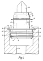
- FIG 4 shows a set-up suitable for the evaluation of the pressure required to cause failure of a connection between a stainless steel adapter 12 and a polyester end cap 10.
- the end cap 10 is not attached to a filter, but is sealed on the filter side 50 by means of a plate 51 attached to a bombfin 52.
- This assembly will be referred to as a dummy filter assembly.
- the adapter 12 is fitted into a socket 53 which resembles the upper section 46a of the aperture 46 of the tube sheet 22, shown in Figure 1 and incorporates two diametrically opposed axially extending slots (not shown), corresponding to the slots 48 of the tube sheet 22, associated circumferentially extending grooves 54 and an annular sealing surface 55.
- the socket 53 is provided with a connection 56 to a source of water under pressure. Water is fed into the socket 53 via the opening 56 causing the pressure within the opening 15 of adapter 12 to increase until the connection fails and the end cap 10 is separated from the adapter 12.
- Table 1 Machine Power (% of 3kW) Time (Seconds) Burst (MPa) Pressure (psi) 30 28 1.00 145 30 25 1.17 170 30 25 1.07 155 60 13 1.10 160 60 12 1.17 170 60 12 1.31 190 90 9 1.45 210 90 7 1.48 215 90 7 1.38 200 90 7 1.17 170 90 6.5 1.24 180 90 6.5 1.28 185 90 6.5 1.38 200 90 6 1.14 165 90 6 0.93 135 60 11 1.21 175 60 11 1.28 185
- the adapters to which tubular filters are conventionally attached for mounting in tube sheets are similar in design to the metallic adapter 12 shown in Figures 1 and 4 but constructed of polyester.
- the dummy filter assembly described above with reference to Figure 4 was attached to such a polyester adapter by the conventional technique of flame welding.
- the polyester adapter was then mounted in the test socket 53 in a similar manner to the stainless steel adapter 12 described above, and then subjected to increasing pressure. At 0.69 MPa (100 psi) pressure the polyester adapter broke. Hence the connection between the stainless steel adapter and the polyester end cap will withstand more pressure than the conventionally used polyester adapter in this test system.
- One of these assemblies was mounted in the test socket 53 shown in Figure 4, formed as part of a polymeric housing provided with an inlet connected to a source of water under pressure (not shown). Water was then admitted into the polymeric housing causing increasing pressure to be applied externally to the adapter/dummy filter assembly.
- the stainless steel adapter/dummy filter assembly remained intact at pressures up to 7.58 MPa (1,100 psi), the maximum pressure which could be used with the test apparatus.
- the polyester adapter/dummy filter assembly failed at approximately 3.45 MPa (500 psi), at which pressure the retaining lugs 42 of the polyester adapter broke off and the dummy filter assembly collapsed.
- the filter module/adapter assembly was tested by the standard Pall forward flow test which tests gas flow through the filter medium, integrity of the filter assembly itself and integrity of the connection between the filter and adapter.
- the test involves presenting an external face of a pre-wetted filter with compressed air at a predetermined pressure.
- the flow of air exiting from the filter/adapter assembly is measured and compared with a range of normal values.
- the normal values are the values expected if the integrity of the filter element and the associated components do not have any leakage paths which allow gas to pass into the interior of the filter other than through the pores of the filter.
- the flange 16a of Figure 5a has a rectangular configuration.
- the flange 16b of Figure 5b has a cross-section that is an equilateral triangle.
- the flange 16c of Figure 5c has parallel inner and outer surfaces 17c,18c with the outer surface 18c projecting axially beyond the inner surface 17c and being connected to the inner surface 17c by an angled end surface 19c.
- the flange 16d of Figure 5d has converging inner and outer surfaces 17d,18d connected by a surface 19d lying in a plane normal to the axis of the adapter 12.
- the flange 16e of Figure 5e is as described above with reference to Figure 2 but with the addition of a second recess 21e formed in the inner surface 17e and axially aligned with the recess 21 in the outer surface 18e.
- the flange 16f of Figure 5f has a rectangular configuration and has a recess 21f formed in the inner surface 17f.
- the flange 16g of Figure 5g is as described above with reference to Figure 2.
- connection method described above need not be used between end caps and mountings. It could be used between any polymeric part and any metallic part where the metallic part is heated and inserted into the polymeric part with the polymeric part forming a key in the recess provided in the metallic part. Even in the embodiments described above relating to filters, the parts need not be as described.
- the flange 16 need not be annular; it could be any suitable shape.
- the recess 21 need not be annular; it could be any shape and it need not be continuous around the flange 16. A number of recesses could be provided.
- the rib 20 is optional.
- An inductive heating system need not be used; any suitable heating system may be used as required.
- the parts need not be connected using the apparatus described above with reference to Figure 3 or tested using the apparatus described above with reference to Figure 4. Any suitable apparatus could be used.
Landscapes
- Engineering & Computer Science (AREA)
- Mechanical Engineering (AREA)
- Chemical & Material Sciences (AREA)
- Chemical Kinetics & Catalysis (AREA)
- Filtration Of Liquid (AREA)
Applications Claiming Priority (2)
| Application Number | Priority Date | Filing Date | Title |
|---|---|---|---|
| GB9405796A GB2287659B (en) | 1994-03-23 | 1994-03-23 | Polymer/metallic connections |
| GB9405796 | 1994-03-23 |
Publications (2)
| Publication Number | Publication Date |
|---|---|
| EP0673664A2 true EP0673664A2 (fr) | 1995-09-27 |
| EP0673664A3 EP0673664A3 (fr) | 1996-07-03 |
Family
ID=10752397
Family Applications (1)
| Application Number | Title | Priority Date | Filing Date |
|---|---|---|---|
| EP19950301736 Ceased EP0673664A3 (fr) | 1994-03-23 | 1995-03-15 | Liaisons de polymère/métal. |
Country Status (2)
| Country | Link |
|---|---|
| EP (1) | EP0673664A3 (fr) |
| GB (1) | GB2287659B (fr) |
Families Citing this family (1)
| Publication number | Priority date | Publication date | Assignee | Title |
|---|---|---|---|---|
| GB2383002B (en) * | 2001-12-13 | 2004-10-27 | Pall Corp | Filter assemblies |
Family Cites Families (5)
| Publication number | Priority date | Publication date | Assignee | Title |
|---|---|---|---|---|
| GB875255A (en) * | 1957-03-15 | 1961-08-16 | Tecalemit Ltd | Improvements in or relating to fluid filters |
| US3976529A (en) * | 1973-01-15 | 1976-08-24 | Sherwood Medical Industries Inc. | Method of sealing filter in tubular fitting for medical injection equipment and the like |
| GB2124532B (en) * | 1982-08-04 | 1985-10-23 | Spirol Ind Limited | Thermal presses for installing metal inserts in thermoplastics material |
| US4819722A (en) * | 1988-01-19 | 1989-04-11 | Johnson Filtration Systems, Inc. | Metal well screen assembly with plastic end fitting and method of attaching same |
| GB2272843B (en) * | 1992-11-11 | 1996-08-14 | Pall Corp | Filter elements |
-
1994
- 1994-03-23 GB GB9405796A patent/GB2287659B/en not_active Expired - Fee Related
-
1995
- 1995-03-15 EP EP19950301736 patent/EP0673664A3/fr not_active Ceased
Also Published As
| Publication number | Publication date |
|---|---|
| GB9405796D0 (en) | 1994-05-11 |
| EP0673664A3 (fr) | 1996-07-03 |
| GB2287659A (en) | 1995-09-27 |
| GB2287659B (en) | 1997-11-26 |
Similar Documents
| Publication | Publication Date | Title |
|---|---|---|
| US4842737A (en) | Filter assembly with an expandable shell | |
| US5741421A (en) | Filter device | |
| CA1304694C (fr) | Filtre a fluide et methode de montage etanche de ce dernier sur son support | |
| EP0181366B1 (fr) | Ameliorations relatives a des filtres | |
| US5304312A (en) | Filter assembly includng filter unit having deformable sealing end caps | |
| AU734627B2 (en) | Filter assembly | |
| US8409312B2 (en) | Filter unit for filtering gaseous fluids | |
| EP0690740B1 (fr) | Joints d'etancheite compressibles pour des elements de filtre et similaire, qui sont actives par un differentiel de pression | |
| US6422395B1 (en) | Filter with preferential fluid affinity | |
| US6347712B1 (en) | Filter | |
| GB2101902A (en) | Tubular filter element for the filtration of fluids | |
| WO1987007176A1 (fr) | Filtre jetable a verrouillage par rotation | |
| ZA200100067B (en) | Round filter cartridge. | |
| US4848448A (en) | Heat exchange assembly | |
| AU671745B2 (en) | Fuel filter with drain/fill/sensor port | |
| EP0673664A2 (fr) | Liaisons de polymère/métal | |
| AU692672B2 (en) | Filtration apparatus | |
| US4908255A (en) | Separate plate and process for producing the same | |
| US3007238A (en) | Method of making a filter assembly | |
| DE19610414C2 (de) | Ölfilter und Verfahren zu seiner Herstellung | |
| EP3868455B1 (fr) | Ensemble connecteur, ensemble de filtre, dispositif de filtre et procédé d'utilisation | |
| GB2233574A (en) | Filter housing | |
| WO1999051317A1 (fr) | Cartouches de filtre pour moyens d'etancheite | |
| US5286381A (en) | Filter assemblies | |
| US4071453A (en) | Diaphragm filtration system |
Legal Events
| Date | Code | Title | Description |
|---|---|---|---|
| PUAI | Public reference made under article 153(3) epc to a published international application that has entered the european phase |
Free format text: ORIGINAL CODE: 0009012 |
|
| AK | Designated contracting states |
Kind code of ref document: A2 Designated state(s): CH DE ES FR IT LI |
|
| PUAL | Search report despatched |
Free format text: ORIGINAL CODE: 0009013 |
|
| AK | Designated contracting states |
Kind code of ref document: A3 Designated state(s): CH DE ES FR IT LI |
|
| 17P | Request for examination filed |
Effective date: 19961209 |
|
| 17Q | First examination report despatched |
Effective date: 19970619 |
|
| GRAG | Despatch of communication of intention to grant |
Free format text: ORIGINAL CODE: EPIDOS AGRA |
|
| STAA | Information on the status of an ep patent application or granted ep patent |
Free format text: STATUS: THE APPLICATION HAS BEEN REFUSED |
|
| 18R | Application refused |
Effective date: 19991007 |