EP0673698B1 - Procédé pour la production de moules - Google Patents
Procédé pour la production de moules Download PDFInfo
- Publication number
- EP0673698B1 EP0673698B1 EP94120497A EP94120497A EP0673698B1 EP 0673698 B1 EP0673698 B1 EP 0673698B1 EP 94120497 A EP94120497 A EP 94120497A EP 94120497 A EP94120497 A EP 94120497A EP 0673698 B1 EP0673698 B1 EP 0673698B1
- Authority
- EP
- European Patent Office
- Prior art keywords
- pressure
- ram
- plate
- compressed air
- moulding
- Prior art date
- Legal status (The legal status is an assumption and is not a legal conclusion. Google has not performed a legal analysis and makes no representation as to the accuracy of the status listed.)
- Expired - Lifetime
Links
- 238000000034 method Methods 0.000 title description 2
- 238000000465 moulding Methods 0.000 claims description 25
- 238000005192 partition Methods 0.000 claims description 18
- 239000000463 material Substances 0.000 claims description 14
- 238000005056 compaction Methods 0.000 claims description 6
- 239000004576 sand Substances 0.000 claims description 2
- 238000005266 casting Methods 0.000 claims 1
- 239000012778 molding material Substances 0.000 description 33
- 238000007906 compression Methods 0.000 description 28
- 230000006835 compression Effects 0.000 description 15
- 238000000280 densification Methods 0.000 description 2
- 238000009423 ventilation Methods 0.000 description 2
- 230000007547 defect Effects 0.000 description 1
- 230000000694 effects Effects 0.000 description 1
- 238000002474 experimental method Methods 0.000 description 1
- 230000002349 favourable effect Effects 0.000 description 1
- 238000011010 flushing procedure Methods 0.000 description 1
- 238000010926 purge Methods 0.000 description 1
- 230000003068 static effect Effects 0.000 description 1
Images


Classifications
-
- B—PERFORMING OPERATIONS; TRANSPORTING
- B22—CASTING; POWDER METALLURGY
- B22C—FOUNDRY MOULDING
- B22C15/00—Moulding machines characterised by the compacting mechanism; Accessories therefor
- B22C15/28—Compacting by different means acting simultaneously or successively, e.g. preliminary blowing and finally pressing
Definitions
- the invention relates to a device according to the preamble of claim 1.
- a method is known from EP patent specification 0 319 453 B1 known for compacting granular molding material, in which the molding material also during mechanical recompression of compressed air and where to Purpose ventilation holes for the compressed air in the Model plate of the device are provided; the air pressure can be compared to the previous one pneumatic pre-compression kept relatively low be so that one of a flushing of the Mold sand can speak.
- the object of the invention is therefore to a device of the type specified in the introduction train that with their help and by means of a single Pressure stamp both in the pneumatic pre-compression as well as in mechanical post-compression the molding material regardless of the shape of the overmolded Model uniform with one over the entire Surface of the molding material approximately constant Surface pressure can be compressed.
- the device should also enable the pre-compression of the Molding material with a constant pressure drop the compressed air with an effective outflow via the ventilation holes as well with a short-term Execute pressure pulse to which the compressed air is exposed becomes.
- the through holes in the pressure stamp are there distributed so that the surface of the molding material consistently the same pressure from the compressed air is exposed. This way the mold space is in its overall configuration this static pressure the Exposed to compressed air and there will be pressure drops within of the molding space and thus especially along the Surface of the molding material largely avoided.
- the effect of mechanical post-compression not affected by the arrangement of the through holes, because the stamp in its outer outline is not affected and the contour continues who can follow models flexibly.
- Vent holes are provided for the compressed air and the through holes according to number and cross section so measured are that a uniform during pre-compression Flow through the molding material takes place, on the other hand, can the through holes according to number and cross section also be dimensioned so that during an impulsive Compressed air feed into the pressure chamber of the one built there Air pressure without delay even in the mold room is present above the surface of the molding material; also there can vent holes for the Compressed air can be provided.
- the pressure stamp is made of an at least partially elastic deformable pressure plate and one the pressure plate assembled rigid frame outside the printing area.
- the stamp can be convenient guided in the housing of the device and on the piston rod of the pressure piston.
- the version the pressure plate through the frame also ensures that permanent deformations of the pressure plate are avoided, because a flow of the pressure plate under the influence of possibly high applied pressure does not take place can.
- a further improvement in the mode of action can be achieved. if the pressure plate is transverse to its direction of movement from several interconnected plate layers consists of different materials Elasticity can exist, the elasticity of the Plate layers expediently in the direction of the printing surface increases.
- the printing plate is in one Case can be carried out very dimensionally stable, even if the Printing area is highly elastic.
- the elasticity of the pressure plate in particular in the area of their printing area is that during mechanical post-compression of the molding material, the outlets abutting the molding material of the through holes through to the pressure plate acting reaction forces are contracted. Die the molding material actually stressful printing surface of the printing stamp as a result increases during the densification, and the Squeezed outlets are in the printing area no longer effective as defects.
- the device according to the invention to generate a pressure pulse for pre-compression be set up in that the pressure chamber from two of one stationary on the housing of the compression device, transverse to the direction of movement of the pressure stamp
- the openings provided in the partition are pneumatically connectable, and that the piston rod is guided through the partition, whereby an interruptible pneumatic connection between the two Subspaces can be produced, for example, in such a way that the openings in the partition and the through holes across the direction of movement of the stamp are arranged offset to each other that at the partition the partial pressure pneumatically are separated from each other.
- the material for at least one Plate layer is incompressible. Otherwise, between the filling device and the molding box a filling frame be arranged.
- the invention overcomes the disadvantages of the prior art in a surprisingly simple way and also does not require any considerable additional effort; however, it is in the described Design extremely versatile and combines the advantages of the known devices with elastic stamps with the advantages of a uniform pneumatic pre-compression.
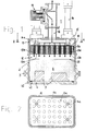
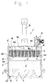
- a device initially exists accordingly Fig. 1 from a compression device 1, the a filling frame 2 is placed on a molding box 3.
- the molding box 3 in turn sits on a model plate 4 on which the (here two) models 5 are located.
- the molding box 3 and part of the filling frame 2 is filled with a molding material 6, over the (horizontal) Surface 61 in a housing 11 of the compression device 1 a mold space 12 is formed, which also bounded by a printing surface 13a of a printing stamp 13 is.
- the pressure stamp 13 is in the housing 11, the filling frame 2 and the molding box 3 in the vertical direction (here four) pressure piston 14 movable, as far as the Mold material 6 allows.
- In the model plate 4 are Vent holes 41 provided that the inside of the Molding box 3 and thus the molding chamber 12 pneumatically with the Connect the area around the device.
- Vent holes 41 inserted screens 42 prevent the Passage of molding material 6.
- the piston-like pressure stamp 13 has a pressure plate 13b on all sides, the one located on the pressure plate 13b, acting on the surface 61 of the molding material 6 Printing surface 13a and also part of the printing plate 13b self-releasing, is clamped in a frame 13c.
- the frame 13c also serves for axially movable storage of the pressure stamp 13 in the housing 11 and for attachment on piston rods 14a of those permanently installed on the housing 11 Pressure piston 14.
- the piston rods 14a are located itself above the plunger 13 in one of these and the housing 11 enclosed pressure chamber 15, which via a Compressed air supply 16 with one omitted in the drawing Compressed air source can be connected via a shut-off device 17 is.
- the flow direction and paths of the compressed air are illustrated in the drawing by directional arrows.
- the mold space 12 more realistically present in FIG. 1 and the open one Shut-off device 17 indicate that the pneumatic Pre-compression of the molding material 6 is started. After the termination thereof is the shut-off device according to FIG. 3 17 closed, and instead the stamp is 13 by actuating the pressure piston 14 for mechanical Post-compression of the molding material 6 onto the molding material 6 opened so that the molding space 12 has disappeared.
- the elasticity of the pressure plate 13b by its constructive Training can be controlled so that to the Molding material 6 outlets 13e of the through holes 13d under the influence of those exerted by the molding material 6 Reaction force are squeezed together and only more narrow slots are left.
- Pressure plate 13b is affected by the reaction force of the Molding material 6 in the area of the edges of the printing surface 13a also deformed towards the housing 11, as in Fig. 3 (and also in Fig. 5) is indicated.
- the axis guide of the pressure stamp 13 in the housing 11 is thereby improved.
- Fig. 4 it can be seen that the pressure chamber 15 'through a partition 18 is divided into two, which in the housing 11 ' is fixed in place, in such a way that in an upper Subspace 15a opens the compressed air supply 16 '.
- the way of representation the compressed air supply 16 'and also the shut-off device 17 ' is intended to symbolically indicate that at this second version with one compared to the first much smaller flow cross-section for those in the Compressed air 15 'comes in compressed air.
- the plunger 13 ' is still on the piston rod 14a 'of a (here only) pressure piston 14' and is initially under its influence at the bottom of the Partition 18 on, a mold space 12 'above the surface 61' of the molding material 6 '.
- the partition 18 is of a size comparable to that of the through holes 13d ' Number of openings 18a provided; these are but axially offset from the through holes 13d ' arranged so that when adjacent to the partition 18 frame 13c the pressure chamber 15 'from the molding chamber 12' pneumatically is separated; in the subspace 15a, even if it is off the compressed air supply 16 'only moderately quickly inflowing Compressed air, a high pressure potential, which also the Pressure stamp 13 'loaded.
- the pressure stamp 13 'of the pressure piston 14' only slightly from the partition 18 removed and moved down, then is created a partial space 15b of the pressure space 15 ', and that in the partial space 15b expanding compressed air can now be accessed Through holes 13d 'the molding material 6' suddenly load and pre-compress impulsively.
- the subspace 15b is further enlarged in accordance with FIG. 5 if by means of of the pressure piston 14 'the mechanical post-compression is initiated, the course of which is otherwise the one the embodiment in Figures 1 to 3 does not differ; consequently, it is also conceivable that the closed in Fig. 5 Shut-off device 17 'still open is and during mechanical re-compression Compressed air flows through the molding material 6 '.
Landscapes
- Engineering & Computer Science (AREA)
- Mechanical Engineering (AREA)
- Moulds For Moulding Plastics Or The Like (AREA)
- Casting Devices For Molds (AREA)
- Casting Or Compression Moulding Of Plastics Or The Like (AREA)
Claims (13)
- Dispositif pour la fabrication de moules de fonderie, comportant une plaque-modèle pourvue d'un modèle, un châssis de moule qui peut être placé sur la plaque-modèle pour la réception d'un demi-produit de fonderie compressible, en particulier d'un sable de fonderie, et un dispositif de compression qui peut être placé sur sur le châssis de moule, une précompression pneumatique et au moins un piston-chasse pour une recompression du demi-produit de fonderie, le piston-chasse (13, 13') étant déformable de manière élastique au moins dans la zone de sa surface de pression (13a, 13a') et un espace de pression (15, 15') étant prévu dans le dispositif de compression (1, 1') au-dessus du piston-chasse (13, 13'), espace dans lequel débouche l'amenée d'air comprimé (16, 16'), caractérisé en ce que, dans le piston-chasse (13, 13'), sont ménagés des passages (13d, 13d') qui relient pneumatiquement un espace de moulage (12, 12') formé entre la surface (61, 61') du demiproduit de fonderie (6, 6') et le piston-chasse (13, 13') à l'espace de pression (15, 15') et en ce que les passages (13d, 13d') sont répartis dans le piston-chasse (13, 13') de telle manière que la surface (61, 61') du demi-produit de fonderie (6, 6') est soumise partout a la même pression d'air comprimé.
- Dispositif selon la revendication 1, caractérisé en ce que des trous d'aération (41, 41') sont prévus dans la plaque-modèle (4, 4') pour l'air comprimé et que le nombre et la section transversale des passages (13d, 13d') sont choisis pour qu'il se produise un écoulement régulier du demi-produit de fonderie (6, 6') pendant la précompression.
- Dispositif selon la revendication 1, caractérisé en ce que le nombre et la section transversale des passages (13d, 13d') sont choisis pour que, pendant une alimentation en air comprimé par impulsions dans l'espace de pression (15, 15'), la pression d'air qui s'y établit ainsi s'applique également immédiatement dans l'espace de moulage (12, 12') sur la surface (61, 61') du demi-produit de fonderie (6, 6').
- Dispositif selon la revendication 3, caractérisé en ce que des trous d'aération (41, 41') pour l'air comprimé sont prévus dans la plaque-modèle (4, 4').
- Dispositif selon l'une des revendications 1 à 4, caractérisé en ce que le piston-chasse (13, 13') est composé d'une plaque de compression (13b, 13b') déformable de manière au moins partiellement élastique et d'un cadre rigide (13c, 13c') encadrant la plaque de pression (13b, 13b') en dehors de la surface de pression (13a, 13a').
- Dispositif selon l'une des revendications 1 à 5, caractérisé en ce que la plaque de compression (13b, 13b') est composée, perpendiculairement à sa direction de déplacement, de plusieurs couches de plaques reliées les unes aux autres.
- Dispositif selon la revendication 6, caractérisé en ce que les couches de plaques sont composées respectivement de matériaux d'élasticités différentes.
- Dispositif selon la revendication 7, caractérisé en ce que l'élasticité des couches de plaques augmente en allant vers la surface de pression (13a, 13a').
- Dispositif selon l'une des revendications 1 à 8, caractérisé en ce que l'élasticité de la plaque de pression (13b, 13b'), en particulier dans la zone de sa surface de pression (13a, 13a'), est choisie de telle manière que, pendant la recompression mécanique du demi-produit de fonderie (6, 6'), les sorties (13e, 13e') des passages (13b, 13b') alors en contact avec le demi-produit de fonderie (6, 6') sont contractées par les forces de réaction qui agissent sur la plaque de pression (13b, 13b').
- Dispositif selon l'une des revendications 3 à 9, caractérisé en ce que l'espace de pression (15') est composé de deux espaces partiels (15a, 15b) séparés l'un de l'autre par une paroi de séparation (18) perpendiculaire à la direction de déplacement du piston-chasse (13') et fixe par rapport au bâti (11') du dispositif de compression (1'), espaces qui peuvent être reliés pneumatiquement l'un à l'autre grâce à des découpes (18a) prévues dans la paroi de séparation (18), et en ce que la tige de piston (14a') est guidée à travers la paroi de séparation (18).
- Dispositif selon la revendication 10, caractérisé en ce que les découpes (18a) dans la paroi de séparation (18) et les passages (13d') sont décalés les uns par rapport aux autres perpendiculairement à la direction de déplacement du piston-chasse (13') de telle manière que, lorsque le piston-chasse (13') est adjacent à la paroi de séparation (18), les espaces partiels (15a, 15b) sont séparés pneumatiquement l'un de l'autre.
- Dispositif selon l'une des revendications 7 à 11, caractérisé en ce que le matériau est incompressible pour au moins une couche de plaques.
- Dispositif selon l'une des revendications 1 à 12, caractérisé en ce qu'un cadre de remplissage est placé entre le dispositif de compression (1, 1') et le châssis de moule (3, 3').
Applications Claiming Priority (2)
| Application Number | Priority Date | Filing Date | Title |
|---|---|---|---|
| DE4409791A DE4409791A1 (de) | 1994-03-22 | 1994-03-22 | Vorrichtung zur Herstellung von Gießformen |
| DE4409791 | 1994-03-22 |
Publications (2)
| Publication Number | Publication Date |
|---|---|
| EP0673698A1 EP0673698A1 (fr) | 1995-09-27 |
| EP0673698B1 true EP0673698B1 (fr) | 1998-12-02 |
Family
ID=6513482
Family Applications (1)
| Application Number | Title | Priority Date | Filing Date |
|---|---|---|---|
| EP94120497A Expired - Lifetime EP0673698B1 (fr) | 1994-03-22 | 1994-12-23 | Procédé pour la production de moules |
Country Status (3)
| Country | Link |
|---|---|
| EP (1) | EP0673698B1 (fr) |
| DE (2) | DE4409791A1 (fr) |
| ES (1) | ES2124359T3 (fr) |
Families Citing this family (3)
| Publication number | Priority date | Publication date | Assignee | Title |
|---|---|---|---|---|
| JP3900447B2 (ja) | 1998-10-28 | 2007-04-04 | 新東工業株式会社 | 鋳物砂の圧縮装置 |
| JP3413798B2 (ja) * | 2000-01-14 | 2003-06-09 | 新東工業株式会社 | 枠付造型装置の造型方法及び造型システム |
| DE10024930A1 (de) * | 2000-05-19 | 2001-11-22 | Josef Mertes | Verfahren und Vorrichtung zum Verdichten von Formstoffen z. B. Giesserei-Formsand |
Citations (1)
| Publication number | Priority date | Publication date | Assignee | Title |
|---|---|---|---|---|
| US3041685A (en) * | 1961-07-14 | 1962-07-03 | Taccone Corp | Diaphragm molding machine |
Family Cites Families (4)
| Publication number | Priority date | Publication date | Assignee | Title |
|---|---|---|---|---|
| JPS55136543A (en) * | 1979-04-11 | 1980-10-24 | Sintokogio Ltd | Cover device of mold molding machine |
| DE3634767A1 (de) * | 1986-10-11 | 1988-04-21 | Wagner Heinrich Sinto Masch | Vorrichtung zur verdichtung von formsand |
| DE3740611C2 (de) * | 1987-12-01 | 1998-07-23 | Wagner Heinrich Sinto Masch | Verfahren zum Verdichten von Formsand |
| ES2048635B1 (es) * | 1991-10-30 | 1996-07-01 | Erana Agustin Arana | Cabezal para maquinas de moldeo de cajas de arena por impacto de aire. |
-
1994
- 1994-03-22 DE DE4409791A patent/DE4409791A1/de not_active Withdrawn
- 1994-12-23 DE DE59407392T patent/DE59407392D1/de not_active Expired - Lifetime
- 1994-12-23 ES ES94120497T patent/ES2124359T3/es not_active Expired - Lifetime
- 1994-12-23 EP EP94120497A patent/EP0673698B1/fr not_active Expired - Lifetime
Patent Citations (1)
| Publication number | Priority date | Publication date | Assignee | Title |
|---|---|---|---|---|
| US3041685A (en) * | 1961-07-14 | 1962-07-03 | Taccone Corp | Diaphragm molding machine |
Also Published As
| Publication number | Publication date |
|---|---|
| EP0673698A1 (fr) | 1995-09-27 |
| ES2124359T3 (es) | 1999-02-01 |
| DE4409791A1 (de) | 1995-09-28 |
| DE59407392D1 (de) | 1999-01-14 |
Similar Documents
| Publication | Publication Date | Title |
|---|---|---|
| DE972225C (de) | Ruehrwerksfreie Maschine zum Herstellen von Giessereikernen | |
| DE7602966U1 (de) | Giesserei-formmaschine fuer kastenformen | |
| EP0170765B1 (fr) | Dispositif pour comprimer du matériel de moulage pour fonderies | |
| EP0062331A1 (fr) | Procédé et dispositif de compactage pneumatique de sable de moulage | |
| EP0673698B1 (fr) | Procédé pour la production de moules | |
| DE3202395A1 (de) | Verfahren und vorrichtung zum pneumatischen verdichten von formsand | |
| DE2933869C2 (de) | Verfahren und Vorrichtung zum Herstellen eines unteren Formteils | |
| DD238745A5 (de) | Verfahren zur herstellung von formteilen | |
| DE2403199C3 (de) | Verfahren und Vorrichtung zur Sandzufuhr und zur Sandverdichtung bei Formenschießmaschinen | |
| DE2544749B2 (de) | Mit einem mischkopf kombiniertes formwerkzeug zum herstellen von formteilen | |
| DE1941736B1 (de) | Verfahren bei kastenlosen Formmaschinen zum Einschiessen des Formsandes und Maschine zur Durchfuehrung desselben | |
| DE2607553C2 (de) | Gießerei-Formmaschine für Kastenformen | |
| DE4319078C2 (de) | Verfahren und Formherstellungsmaschine zur Herstellung von Gußformen oder Gußformteilen aus Formsand | |
| EP0131723B1 (fr) | Dispositif pour le serrage de matière de moulage de fonderie à l'aide de gaz comprimé | |
| EP0128336B1 (fr) | Dispositif pour le serrage de sable de fonderie | |
| DE2923271A1 (de) | Giesserei-formmaschine | |
| DE3914160C1 (fr) | ||
| DE3432368C2 (fr) | ||
| DE3717558C3 (de) | Verfahren zum Herstellen von Sandgießformen von Modellen | |
| DE3319496C2 (fr) | ||
| DE19913119B4 (de) | Verfahren zur Herstellung einer Sandform | |
| DE3801497C2 (de) | Schießkopf für eine Saug-Preß-Formmaschine und Verfahren zu deren Betrieb | |
| DE3839475C2 (fr) | ||
| CH653579A5 (de) | Verfahren zum verdichten von koernigen formstoffen, insbesondere giessereiformstoffen, und vorrichtung zur durchfuehrung des verfahrens. | |
| DE29507011U1 (de) | Vorrichtung zum Verdichten von Formsand |
Legal Events
| Date | Code | Title | Description |
|---|---|---|---|
| PUAI | Public reference made under article 153(3) epc to a published international application that has entered the european phase |
Free format text: ORIGINAL CODE: 0009012 |
|
| AK | Designated contracting states |
Kind code of ref document: A1 Designated state(s): CH DE ES FR GB IT LI NL SE |
|
| 17P | Request for examination filed |
Effective date: 19950906 |
|
| 17Q | First examination report despatched |
Effective date: 19970624 |
|
| GRAG | Despatch of communication of intention to grant |
Free format text: ORIGINAL CODE: EPIDOS AGRA |
|
| GRAG | Despatch of communication of intention to grant |
Free format text: ORIGINAL CODE: EPIDOS AGRA |
|
| GRAH | Despatch of communication of intention to grant a patent |
Free format text: ORIGINAL CODE: EPIDOS IGRA |
|
| TPAD | Observations filed by third parties |
Free format text: ORIGINAL CODE: EPIDOS TIPA |
|
| GRAH | Despatch of communication of intention to grant a patent |
Free format text: ORIGINAL CODE: EPIDOS IGRA |
|
| GRAA | (expected) grant |
Free format text: ORIGINAL CODE: 0009210 |
|
| AK | Designated contracting states |
Kind code of ref document: B1 Designated state(s): CH DE ES FR GB IT LI NL SE |
|
| REG | Reference to a national code |
Ref country code: CH Ref legal event code: NV Representative=s name: LUCHS & PARTNER PATENTANWAELTE Ref country code: CH Ref legal event code: EP |
|
| GBT | Gb: translation of ep patent filed (gb section 77(6)(a)/1977) |
Effective date: 19981209 |
|
| REF | Corresponds to: |
Ref document number: 59407392 Country of ref document: DE Date of ref document: 19990114 |
|
| REG | Reference to a national code |
Ref country code: ES Ref legal event code: FG2A Ref document number: 2124359 Country of ref document: ES Kind code of ref document: T3 |
|
| ET | Fr: translation filed | ||
| PLBE | No opposition filed within time limit |
Free format text: ORIGINAL CODE: 0009261 |
|
| STAA | Information on the status of an ep patent application or granted ep patent |
Free format text: STATUS: NO OPPOSITION FILED WITHIN TIME LIMIT |
|
| 26N | No opposition filed | ||
| REG | Reference to a national code |
Ref country code: GB Ref legal event code: IF02 |
|
| PGFP | Annual fee paid to national office [announced via postgrant information from national office to epo] |
Ref country code: GB Payment date: 20101221 Year of fee payment: 17 |
|
| PGFP | Annual fee paid to national office [announced via postgrant information from national office to epo] |
Ref country code: SE Payment date: 20111220 Year of fee payment: 18 Ref country code: CH Payment date: 20111222 Year of fee payment: 18 Ref country code: FR Payment date: 20120103 Year of fee payment: 18 Ref country code: NL Payment date: 20111221 Year of fee payment: 18 Ref country code: ES Payment date: 20111219 Year of fee payment: 18 |
|
| REG | Reference to a national code |
Ref country code: NL Ref legal event code: V1 Effective date: 20130701 |
|
| PG25 | Lapsed in a contracting state [announced via postgrant information from national office to epo] |
Ref country code: SE Free format text: LAPSE BECAUSE OF NON-PAYMENT OF DUE FEES Effective date: 20121224 |
|
| REG | Reference to a national code |
Ref country code: CH Ref legal event code: PL |
|
| GBPC | Gb: european patent ceased through non-payment of renewal fee |
Effective date: 20121223 |
|
| REG | Reference to a national code |
Ref country code: FR Ref legal event code: ST Effective date: 20130830 |
|
| PG25 | Lapsed in a contracting state [announced via postgrant information from national office to epo] |
Ref country code: CH Free format text: LAPSE BECAUSE OF NON-PAYMENT OF DUE FEES Effective date: 20121231 Ref country code: NL Free format text: LAPSE BECAUSE OF NON-PAYMENT OF DUE FEES Effective date: 20130701 Ref country code: LI Free format text: LAPSE BECAUSE OF NON-PAYMENT OF DUE FEES Effective date: 20121231 |
|
| PG25 | Lapsed in a contracting state [announced via postgrant information from national office to epo] |
Ref country code: FR Free format text: LAPSE BECAUSE OF NON-PAYMENT OF DUE FEES Effective date: 20130102 Ref country code: GB Free format text: LAPSE BECAUSE OF NON-PAYMENT OF DUE FEES Effective date: 20121223 |
|
| PGFP | Annual fee paid to national office [announced via postgrant information from national office to epo] |
Ref country code: IT Payment date: 20131217 Year of fee payment: 20 |
|
| REG | Reference to a national code |
Ref country code: ES Ref legal event code: FD2A Effective date: 20140307 |
|
| PGFP | Annual fee paid to national office [announced via postgrant information from national office to epo] |
Ref country code: DE Payment date: 20140218 Year of fee payment: 20 |
|
| PG25 | Lapsed in a contracting state [announced via postgrant information from national office to epo] |
Ref country code: ES Free format text: LAPSE BECAUSE OF NON-PAYMENT OF DUE FEES Effective date: 20121224 |
|
| REG | Reference to a national code |
Ref country code: DE Ref legal event code: R071 Ref document number: 59407392 Country of ref document: DE |
|
| REG | Reference to a national code |
Ref country code: DE Ref legal event code: R071 Ref document number: 59407392 Country of ref document: DE |