EP0673728B1 - Rasoir à sec avec verrouillage du cadre portant la feuille perforée coupante - Google Patents
Rasoir à sec avec verrouillage du cadre portant la feuille perforée coupante Download PDFInfo
- Publication number
- EP0673728B1 EP0673728B1 EP95102480A EP95102480A EP0673728B1 EP 0673728 B1 EP0673728 B1 EP 0673728B1 EP 95102480 A EP95102480 A EP 95102480A EP 95102480 A EP95102480 A EP 95102480A EP 0673728 B1 EP0673728 B1 EP 0673728B1
- Authority
- EP
- European Patent Office
- Prior art keywords
- elements
- shaving apparatus
- spring
- control
- dry shaving
- Prior art date
- Legal status (The legal status is an assumption and is not a legal conclusion. Google has not performed a legal analysis and makes no representation as to the accuracy of the status listed.)
- Expired - Lifetime
Links
- 239000011888 foil Substances 0.000 title 1
- 238000010168 coupling process Methods 0.000 claims abstract description 31
- 230000008878 coupling Effects 0.000 claims abstract description 30
- 238000005859 coupling reaction Methods 0.000 claims abstract description 30
- 210000003128 head Anatomy 0.000 description 8
- 238000004519 manufacturing process Methods 0.000 description 3
- 239000000463 material Substances 0.000 description 3
- 238000000034 method Methods 0.000 description 3
- 210000001061 forehead Anatomy 0.000 description 2
- 230000003993 interaction Effects 0.000 description 2
- 230000000712 assembly Effects 0.000 description 1
- 238000000429 assembly Methods 0.000 description 1
- 238000004140 cleaning Methods 0.000 description 1
- 238000005520 cutting process Methods 0.000 description 1
- 238000009826 distribution Methods 0.000 description 1
- 238000003825 pressing Methods 0.000 description 1
- 230000002040 relaxant effect Effects 0.000 description 1
- 230000001960 triggered effect Effects 0.000 description 1
Images


Classifications
-
- B—PERFORMING OPERATIONS; TRANSPORTING
- B26—HAND CUTTING TOOLS; CUTTING; SEVERING
- B26B—HAND-HELD CUTTING TOOLS NOT OTHERWISE PROVIDED FOR
- B26B19/00—Clippers or shavers operating with a plurality of cutting edges, e.g. hair clippers, dry shavers
- B26B19/02—Clippers or shavers operating with a plurality of cutting edges, e.g. hair clippers, dry shavers of the reciprocating-cutter type
- B26B19/04—Cutting heads therefor; Cutters therefor; Securing equipment thereof
- B26B19/048—Complete cutting head being movable
-
- B—PERFORMING OPERATIONS; TRANSPORTING
- B26—HAND CUTTING TOOLS; CUTTING; SEVERING
- B26B—HAND-HELD CUTTING TOOLS NOT OTHERWISE PROVIDED FOR
- B26B19/00—Clippers or shavers operating with a plurality of cutting edges, e.g. hair clippers, dry shavers
- B26B19/02—Clippers or shavers operating with a plurality of cutting edges, e.g. hair clippers, dry shavers of the reciprocating-cutter type
- B26B19/04—Cutting heads therefor; Cutters therefor; Securing equipment thereof
- B26B19/10—Cutting heads therefor; Cutters therefor; Securing equipment thereof involving two or more different types of reciprocating cutting elements, e.g. a pair of toothed shearing elements combined with a pair of perforated cutting elements or a combined toothed and perforated cutting assembly
- B26B19/102—Cutting heads therefor; Cutters therefor; Securing equipment thereof involving two or more different types of reciprocating cutting elements, e.g. a pair of toothed shearing elements combined with a pair of perforated cutting elements or a combined toothed and perforated cutting assembly with a secondary cutting unit being translated or slid into an operating position
Definitions
- the invention relates to a dry shaving apparatus with a housing part provided on the housing, in which at least two locking elements and at least one spring are arranged, and with a frame carrying at least one upper knife, on which at least two coupling elements for the locking elements are provided.
- a dry shaver of the type mentioned is known from DE 40 29 377 C1.
- This dry shaver is equipped, for example, with four locking elements, one of which is shown, for example, in FIG. 1.
- the locking elements engage in recesses which are formed on the inside of the two longitudinal side walls of the frame carrying at least one upper knife. Due to the manufacturing process, there are different locking forces which hold the locking elements in the corresponding recesses on the upper frame and which either make the upper knife frame uncoupling from the housing part too light or too heavy, e.g. B. for the purpose of cleaning the lower knife, result.
- a dry shaver is known, with a movable lower knife and a cooperating with the lower knife upper knife, which is clamped in a subframe, which is provided in both ends with a spring-elastic locking element, each in one in the forehead cheeks the recesses provided in the razor housing snap into place and can be actuated by spring-elastic unlocking keys arranged in the forehead cheeks for the purpose of removing the auxiliary frame with an upper knife from the razor housing.
- the invention has for its object to lock one with at least one To improve the upper knife-equipped frame with a housing part of the dry shaver.
- this object is achieved in that at least one control element which is arranged to be displaceable against the pressure of the at least one spring parallel to the axis xx is provided for controlling the locking elements, the locking elements being arranged movably transversely to the axis xx in the housing part and against the pressure of the spring acting on the locking elements are displaceable by the control element.
- a major advantage of the invention is that by means of the control element which is displaceably arranged in the housing part, all locking elements in engagement with coupling elements can be controlled into an unlocking position, so that the frame equipped with at least one upper knife can be easily removed by the user without exerting an unlocking pressure on the frame can be.
- At least two locking elements are provided on each control element.
- the locking elements can be controlled with the control element by means of control cams engaging in control grooves.
- the locking elements are provided with control grooves which run obliquely to the direction of movement of the control element.
- the control cams are preferably provided on the control element.
- This structurally very simply designed and therefore very inexpensive to manufacture embodiment of the invention ensures, via the oblique control grooves provided in the locking elements and the control cams provided on the control element, that all locking elements are simultaneously transported against the pressure of a spring into an unlocking position and with an upper knife release equipped frame.
- the user releases pressure from the control element, as a result of which the springs acting on the locking elements move the locking elements and the control element back into a starting position corresponding to the locking position.
- a further solution to the above-mentioned object is that at least one control element which is displaceable against the pressure of the at least one spring parallel to the axis xx is provided for controlling the locking elements, the locking elements being fixedly arranged on the control element and with the control element against the pressure of a acting on the control spring are displaceable.
- the spring rests on the one hand on the control element and on the other hand on an end cheek or an end wall or a leg of the housing part.
- This embodiment according to the invention ensures, with a few components, an optimal locking or unlocking of a frame equipped with an upper knife with a housing part of the dry shaving apparatus.
- the coupling elements and locking elements are preferably provided with inclined surfaces.
- the spring-loaded locking elements press with their inclined surfaces onto correspondingly inclined surfaces of the coupling elements provided in the frame. Force components are formed over these inclined surfaces, which press the frame firmly onto the housing part.
- the force components of the holding forces or the pulling forces of the frame from the housing part can be influenced or advantageously designed by a corresponding angular size of the inclined surfaces to a coordinate plane.
- At least one actuating element is provided for actuating the control element.
- an actuating element is provided on the control element, a further actuating element being associated with this actuating element.
- the further actuating element is resiliently arranged in at least one of the support arms or in at least one of the end cheeks of the housing part.
- two control elements are arranged in the housing part so as to be movable against the pressure of at least one spring.
- two locking elements and an actuating element are provided on each of the control elements.
- This embodiment according to the invention provides a force-neutral actuation, since two control elements against the pressure of a spring are to be actuated against one another simultaneously to unlock a frame with an upper knife, as well as easy actuation, since the spring forces of the springs acting directly or indirectly on the locking elements can be reduced.
- the housing part is designed as an integral part of the housing.
- the housing part is movably arranged on the housing between two support arms or end cheeks.
- Fig. 1 the upper part of a dry shaver, the housing with 1, the on and off switch with 2, the long hair cutting system with 3, the top of the housing with 4, the drive pin protruding from the opening 5 in the top of the housing 4 with 6, in Extension of the narrow housing sides 7 and 8 extending support arms with 9 and 10 and the shaving head system pivotally mounted about an axis xx by means of bearing screws 11 designated SK.
- the support arms 9, 10 are part of a Plastic existing housing head part GK - see Fig. 1 - or molded directly onto the housing - see Fig. 2.
- the shaving head system SK shows a pair of shaving heads 14 and 15 running parallel to one another, which are formed by two lower knives 16 and 17 and by upper knives 18 which surround the lower knives 16 and 17 in a curved manner.
- the lower cutters 16 and 17 are resiliently mounted on a common coupling element 19.
- the coupling element 19 is coupled to a drive element 47, which is part of a swing bridge 61 mounted in the housing part 21 - see FIG. 2.
- the latter is provided with two transverse ribs 22 and 23, in the intermediate space 24 of which the drive pin 6 engages.
- the transverse ribs 22 and 23 of the swing bridge 61 oscillate when the drive is switched on within the opening 26 provided in the base plate 27 in the housing part 21 of the shaving head frame.
- Fig. 2 is corresponding to Fig. 1, the housing with 1, the molded on the housing, made of a plastic material, support arms with 9 and 10, which protrudes from the opening 5 in the top 4 of the housing, in the space 24 of the swing bridge 61 provided transverse ribs 22, 23 projecting drive pin 6.
- the housing part 21 consisting of a plastic material, of which the front side walls 62, 63 and the inner wall 64 projecting into the interior can be seen in FIG. 2, is pivotably mounted on the support arms 9 and 10 by means of bearing screws 11.
- the base plate 27 of the housing part 21, which is made of plastic material, is U-shaped. The legs 66, 67 of the base plate 27 extend parallel to the end walls 62, 63 of the housing part 21.
- the base plate 27 has an opening 26 into which the transverse ribs 22, 23 of the swing bridge 61 protrude for the purpose of coupling with the drive pin 6.
- the drive element 47 serving to couple with the bearing pin 42 of the coupling element 19 is molded into the plate 70 and is thus part of the swing bridge 61.
- the seal 71 closes the opening 60 provided in the inner wall 64 of the housing part 21.
- recesses 28 are provided in the frame 20 for the engagement of locking elements 29 which are resiliently arranged in the housing part 21, with at least two locking elements 29 also being provided for the purpose of securely fastening the frame 20 on the housing part 21 In the frame 20 correspondingly arranged recesses 28 are provided.
- FIG. 1 which is explained in more detail with reference to FIGS. 2 to 7, for example, four locking elements are arranged in the inner wall 64 of the housing part 21 so as to be movable transversely to the direction of extension of the axis xx, a spring 31 being provided between two locking elements 29 mounted opposite each other - See Fig. 3 to 7 - are arranged.
- openings 32 are provided in the inner wall 64 of the housing part 21, in which the locking elements 29 either slide directly - see FIGS. 4 to 7 - or with the aid of assembly, the mounting and the guidance of the locking elements 29 to facilitate Support elements 33 are arranged protruding from the openings 32 - see FIGS. 2 and 3.
- the support elements 33 also ensure a preassembly of latch assemblies, consisting of a support element 33, two latch elements which are movably guided in the support element 33 against the pressure of a spring 31 29, whose mobility out of the carrier element 33 is limited by means of cooperating stop elements 34, 35 provided on the carrier element 33 and on the locking elements 29.
- two holding elements 40, 41 with openings 42, 43 are formed, into which snap-in elements 44 provided on the base plate 27 engage, around the support elements 33 with the spring 31 and the locking elements 29 with the base plate 27 to couple.
- two step-shaped shoulders 45, 46 are provided, running parallel to the axis xx, for the slidable guidance of a control element 30 provided with control cams 48.
- the control cams 48 project through the openings 50 provided in the outer wall 36 of the carrier elements 33 and are in engagement with control grooves 49 provided in the locking elements 29.
- the control element 30 is on the step-shaped shoulders 45, 46 movably held or guided.
- two holding elements 38 having inclined side walls are provided at a predetermined distance from one another in order to form a holding groove 37.
- a holding element 39 provided on the inner wall 64, which engages in the holding groove by coupling the inner wall 64 to the bottom part 27, the provided support elements 33 are immovably held or fixed in the housing part 21.
- FIG. 4 shows a schematic illustration of the control element 30 and four locking elements 29 which are coupled to the control element 30 via control grooves 49 and control cams 48.
- the control grooves in the locking elements 29 extend at an angle of approximately 45 degrees to an axis xx such that when pressure is exerted on the actuating element 52 in the direction of arrow B, the control cams 48 act on one of the inclined side walls of the control grooves 49 and the locking elements 29 move against the pressure of the spring 31 arranged between two opposite locking elements 29 in the arrow directions A and C indicated in each case transversely to the axis xx.
- the actuating element 52 provided on the control element 30 projects through an opening 53 provided in the leg 67 of the base plate 27 and projects into a further opening 54 provided in the front side wall 63.
- an actuating element 55 is resiliently mounted such that, by exerting pressure on the actuating element 55, the control element 30 is displaced in the direction of arrow B via the actuating element 52, as a result of which the control cams 48 provided on the control element act on the inclined walls of the control grooves 49 and the opposite locking elements 29 move in the indicated arrow directions A and C against each other against the pressure of the spring 31.
- This sequence of movements of the locking elements 29 is shown in FIGS. 4 to 7.
- the opening 51 provided in the control element 30 serves to carry out drive elements and coupling elements from the drive pin 6 to the lower cutters 16, 17 - see FIG. 2.
- FIGS. 8 and 9 shows, for example, two congruently designed control elements 30 ', which alternatively instead of a one-piece control element 30 - e.g. 4 - can be arranged movably in a housing part 21.
- An actuating element 52 is provided on each of the two control elements 30 'and can be acted upon by an actuating element 55 arranged in each of the support arms 8 and 9 - see FIG. 2.
- the actuating elements 55 When the actuating elements 55 are actuated, they first act on the actuating elements 52 and thus move the control elements 30 ′ towards one another.
- the control cams 48 of the control elements 30 ' which are in engagement with the control grooves 49 each move two locking elements 29 against the pressure of a spring 31 arranged between two locking elements in the respectively indicated arrow directions A and C transversely to the axis xx, as a result of which the locking elements 29 become disengaged the coupling elements 28 formed as recesses arrive in the frame 20 and release the frame 20 for removal from the housing parts 21.
- the springs 31 move the respective control elements 30 'back into a starting position corresponding to the locking position - see FIG. 8 -.
- the previously described locking or unlocking of four locking elements 29 with corresponding four coupling elements 28 provided in a frame 20 can also be effected by using and arranging only one spring 31 instead of two springs 31 according to FIGS. 8 and 9. If only one spring 31 is arranged, this spring 31 would have to be provided between the two control elements 30 ′ which can be moved relative to one another - not shown -.
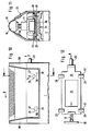
- FIG. 10 and FIG. 11 are on the housing 1 of the Dry shaving apparatus provided two end cheeks 80 and 90, between which the frame 20 equipped with an upper knife 18 is removably arranged.
- the frame 20 equipped with an upper knife 18 is removably arranged.
- locking elements 29 movable on the one hand in the upper housing part 21 of the housing 1 against the pressure of a spring 31 and, on the other hand, coupling elements 28 arranged on the frame 20 are provided.
- the locking elements 29 are part of a control element 30 which is movably mounted in the housing part 21.
- An actuating element 52 which is passed through the end cheek 90, for example, is further provided on the control element and can be actuated directly by the user for the purpose of unlocking the frame 20 carrying an upper knife 18.
- the spring 31 is arranged in the housing part 21, which is supported on the one hand on the control element 30 and on the other hand on a component of the housing part 21, for example on the end cheek 80.
- the coupling elements 28 and on the locking elements 29 - in the direction of arrow D - obliquely aligned surfaces 56 and 57 are provided, such that when the control element 30 is displaced in the direction of arrow B against the pressure of the spring 31, the unlocking is canceled in such a way that the Coupling elements 28 provided on the frame 20 are moved with their inclined surfaces 56 past the inclined surfaces 57 of the locking elements 29 in the course of the removal process of the frame 20.
- the removal process of the frame 20 with the upper knife 18 in the direction of arrow E is supported by the pressure of the spring 58 pressing the lower knife 16 against the upper knife 18 after the coupling elements 28 are released.
- the inclined surfaces 56 of the coupling elements 28 facilitate during the coupling process of the frame 20 with the Housing part 21, the locking of housing part 21 with the frame 20 by sliding along the inclined surfaces 56 on the inclined surfaces 57 of the locking elements 29.
- the cam-shaped coupling elements 28 press the control element 30 over the locking elements 29 against the pressure of the spring 31 in the course of this process Direction of arrow B until, after sliding over the inclined surfaces 57 of the locking elements 29, the control element 30 with the locking elements 29 is automatically moved into the locking position by relaxing the spring 31, as is shown in FIG. 10 and FIG. 11.
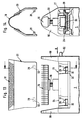
- FIG. 13 and 14 show one of the upper housing part 21 of the housing 1 removed frame 20 with attached upper knife 18.
- coupling elements 28 are formed on the inside thereof with inclined surfaces 56 each running in the same direction - see cross section according to FIG. 14 -.
- the housing part 21 of the housing 1 has a detachably arranged inner wall 64, in which openings 32 are provided for the passage of the locking elements 29 which can be moved in the direction of the arrow B with the control element 30 against the pressure of a spring 31 and which, in cooperation with the coupling elements 28, provide a coupling or decoupling of the frame 20 with the upper housing part 21 of the dry shaving apparatus, the inclined surfaces 57 facilitating the coupling of the frame 20 by sliding along the inclined surfaces 56 provided on the coupling elements 28.
Landscapes
- Life Sciences & Earth Sciences (AREA)
- Forests & Forestry (AREA)
- Engineering & Computer Science (AREA)
- Mechanical Engineering (AREA)
- Dry Shavers And Clippers (AREA)
- Undergarments, Swaddling Clothes, Handkerchiefs Or Underwear Materials (AREA)
- Laminated Bodies (AREA)
Claims (15)
- Rasoir à sec comprenant une partie de boîtier (21) prévue sur le boîtier (1), dans laquelle sont agencés au inoins deux éléments de verrouillage (29) et au moins un ressort (31), ainsi qu'un cadre (20) qui porte au moins un couteau supérieur (18) et sur lequel sont prévus au moins deux éléments d'accouplement (28) pour les éléments de verrouillage (29), caractérisé en ce que, pour commander les éléments de verrouillage (29) il est prévu au moins un élément de commande (30, 30') mobile parallèlement à un axe (X-X) de la partie de boîtier (21) à l'encontre de la pression dudit au moins un ressort (31), les éléments de verrouillage (29) étant agencés dans la partie de boîtier (21) de façon mobile perpendiculairement à l'axe X-X, et pouvant être déplacés par l'élément de commande (30, 30') à l'encontre de la pression du ressort (31) qui agit sur les éléments de verrouillage (29).
- Rasoir à sec comprenant une partie de boîtier (21) prévue sur le boîtier (1), dans laquelle sont agences au moins deux éléments de verrouillage (29) et au moins un ressort (31), ainsi qu'un cadre (20) qui porte au moins un couteau supérieur (18) et sur lequel sont prévus au moins deux éléments d'accouplement (28) pour les éléments de verrouillage (29), caractérisé en ce que, pour commander les éléments de verrouillage (29), il est prévu au moins un élément de commande (30, 30') mobile parallèlement à un axe (X-X) de la partie de boîtier (21) à l'encontre de la pression dudit au moins un ressort (31), les éléments de verrouillage (29) étant agencés de façon fixe sur l'élément de commande (30, 30') et étant susceptibles d'être déplacés avec l'élément de commande (30, 30') à l'encontre de la pression d'un ressort (31) qui agit sur l'élément de commande (30, 30').
- Rasoir à sec selon l'une ou l'autre des revendications 1 et 2, caractérisé en ce que sur chaque élément de commande (30, 30') sont prévus au moins deux éléments de verrouillage (29).
- Rasoir à sec selon la revendication 1, caractérisé en ce que les éléments de verrouillage (29) avec l'élément de commande (30) sont susceptibles d'être commandés au moyen de cames de commande (48) engagées dans des rainures de commande (49).
- Appareil rasoir à sec selon la revendication 4, caractérisé en ce que les éléments de verrouillage (29) sont pourvus de rainures de commande (49) qui s'étendent en oblique par rapport à la direction de déplacement (direction de la flèche B) de l'élément de commande (30).
- Rasoir à sec selon l'une ou l'autre des revendications 4 et 5, caractérisé en ce que les cames de commande (48) sont prévues sur l'élément de commande (30).
- Rasoir à sec selon la revendication 2, caractérisé en ce que le ressort (31) s'appuie d'une part sur l'élément de commande (30, 30') et d'autre part sur une joue frontale (80, 90) ou sur une paroi latérale frontale (62, 63) ou sur un bras (66, 67) de la partie de boîtier (21).
- Rasoir à sec selon l'une quelconque des revendications précédentes, caractérisé en ce que les éléments d'accouplement (28) et les éléments de verrouillage (29) sont pourvus de surfaces en oblique (56, 57).
- Rasoir à sec selon l'une quelconque des revendications précédentes, caractérisé en ce qu'il est prévu au moins un élément d'actionnement (52, 55) pour actionner l'élément de commande (30, 30').
- Rasoir à sec selon la revendication 9, caractérisé en ce qu'il est prévu un élément d'actionnement (52) sur l'élément de commande (30, 30'), et en ce qu'un autre élément d'actionnement (55) est associé à ce premier élément d'actionnement (52).
- Rasoir à sec selon la revendication 10, caractérisé en ce que l'élément d'actionnement (55) est agencé de manière élastique dans l'un au moins des bras de support (9, 10) ou l'une au moins des joues frontales (80, 90) de la partie de boîtier (21).
- Rasoir à sec selon l'une quelconque des revendications précédentes, caractérisé en ce que dans la partie de boîtier (21) sont agencés deux éléments de commande (30, 30') mobiles à l'encontre de la pression d'au moins un ressort (31).
- Rasoir à sec selon la revendication 12, caractérisé en ce qu'il est prévu sur chacun des éléments de commande (30, 30') deux éléments de verrouillage (29) ainsi qu'un élément d'actionnement (52).
- Rasoir à sec selon l'une quelconque des revendications précédentes, caractérisé en ce que la partie de boîtier est agencée de façon mobile sur le boîtier (1) entre deux bras de support (9, 10) ou joues frontales (80, 90).
- Rasoir à sec selon l'une quelconque des revendications 1 à 12, caractérisé en ce que la partie de boîtier (21) est réalisée sous forme d'un composant fixe du boîtier (1).
Applications Claiming Priority (2)
| Application Number | Priority Date | Filing Date | Title |
|---|---|---|---|
| DE4410543 | 1994-03-26 | ||
| DE4410543A DE4410543C1 (de) | 1994-03-26 | 1994-03-26 | Trockenrasierapparat mit Obermesser-Rahmenverriegelung |
Publications (2)
| Publication Number | Publication Date |
|---|---|
| EP0673728A1 EP0673728A1 (fr) | 1995-09-27 |
| EP0673728B1 true EP0673728B1 (fr) | 1996-12-18 |
Family
ID=6513931
Family Applications (1)
| Application Number | Title | Priority Date | Filing Date |
|---|---|---|---|
| EP95102480A Expired - Lifetime EP0673728B1 (fr) | 1994-03-26 | 1995-02-22 | Rasoir à sec avec verrouillage du cadre portant la feuille perforée coupante |
Country Status (7)
| Country | Link |
|---|---|
| US (1) | US5542179A (fr) |
| EP (1) | EP0673728B1 (fr) |
| JP (1) | JPH07299262A (fr) |
| CN (1) | CN1097505C (fr) |
| AT (1) | ATE146394T1 (fr) |
| DE (2) | DE4410543C1 (fr) |
| HK (1) | HK33897A (fr) |
Cited By (1)
| Publication number | Priority date | Publication date | Assignee | Title |
|---|---|---|---|---|
| WO2000005041A1 (fr) | 1998-07-20 | 2000-02-03 | Braun Gmbh | Appareil de rasage a sec |
Families Citing this family (17)
| Publication number | Priority date | Publication date | Assignee | Title |
|---|---|---|---|---|
| DE19632333C1 (de) | 1996-08-10 | 1997-06-05 | Braun Ag | Trockenrasierapparat |
| DE19832473C1 (de) | 1998-07-20 | 2000-03-30 | Braun Gmbh | Trockenrasierapparat |
| AT2988U1 (de) | 1998-07-24 | 1999-08-25 | Payer Lux Elektroprod | Trockenrasierapparat |
| USD428671S (en) * | 1998-11-02 | 2000-07-25 | Braun Gmbh | Shaving part for shaver |
| KR200396685Y1 (ko) * | 2005-06-21 | 2005-09-26 | 오태준 | 이단걸림 외도대를 구비한 전기면도기 |
| DE102005044176A1 (de) * | 2005-09-16 | 2007-03-29 | Braun Gmbh | Haarentfernungsgerät |
| DE102006030946A1 (de) * | 2006-07-05 | 2008-01-10 | Braun Gmbh | Schereinheit für einen Trockenrasierer |
| US20110203124A1 (en) * | 2010-02-19 | 2011-08-25 | Kelly Daniel Bridges | Protective Covers for Wet Shaving Razors |
| EP2591889B1 (fr) * | 2011-11-08 | 2015-09-16 | Braun GmbH | Rasoir électrique comportant une tête de rasage pivotante |
| JP6333411B2 (ja) | 2014-04-18 | 2018-05-30 | コーニンクレッカ フィリップス エヌ ヴェKoninklijke Philips N.V. | 刃セット、毛切断装置、及び、関連の製造方法 |
| US20170173804A1 (en) * | 2015-12-17 | 2017-06-22 | Troy Patrick Worth | Opposed dual foil shaving heads and trimmer |
| EP3300863B1 (fr) * | 2016-09-28 | 2020-06-17 | Braun GmbH | Rasoir électrique |
| EP3300861B1 (fr) | 2016-09-28 | 2019-07-03 | Braun GmbH | Dispositif entraîné électriquement |
| EP3300845B1 (fr) * | 2016-09-28 | 2019-10-23 | Braun GmbH | Couplage de rasoir et rasoir électrique doté d'un couplage |
| USD983455S1 (en) * | 2020-10-15 | 2023-04-11 | Skull Shaver, Llc | Electric shaver foil head |
| JP2022155347A (ja) * | 2021-03-30 | 2022-10-13 | パナソニックIpマネジメント株式会社 | 電気かみそり |
| CN114102680B (zh) * | 2021-11-12 | 2023-10-13 | 深圳市阿可美电器有限公司 | 一种带有接触面可调弧度的护理用剃须刀 |
Family Cites Families (12)
| Publication number | Priority date | Publication date | Assignee | Title |
|---|---|---|---|---|
| US3590482A (en) * | 1969-06-06 | 1971-07-06 | Sunbeam Corp | Comb support and release mechanism for electric dry shaver |
| US3760498A (en) * | 1971-08-18 | 1973-09-25 | Schick Electric Inc | Electric shaver with improved end cover assembly |
| NL7406636A (nl) * | 1974-05-17 | 1975-11-19 | Philips Nv | Ontgrendeling scheerhoofd. |
| NL7406635A (nl) * | 1974-05-17 | 1975-11-19 | Philips Nv | Ontgrendeling scheerhoofd. |
| US3997969A (en) * | 1975-06-04 | 1976-12-21 | Sperry Rand Corporation | Electric dry shaver |
| DE3415122C2 (de) * | 1984-04-21 | 1986-03-06 | Braun Ag, 6000 Frankfurt | Trockenrasierapparat mit einschiebbarem Hilfsrahmen |
| DE3415121C2 (de) * | 1984-04-21 | 1986-06-12 | Braun Ag, 6000 Frankfurt | Abnehmbarer Scherkopfrahmen |
| DE8629679U1 (de) * | 1986-11-06 | 1988-03-10 | N.V. Philips' Gloeilampenfabrieken, Eindhoven | Trockenrasierapparat |
| GB2201114B (en) * | 1987-02-20 | 1991-04-03 | Matsushita Electric Works Ltd | A dry shaver with a readily replaceable outer shearing foil |
| US4926552A (en) * | 1988-01-26 | 1990-05-22 | Matsushita Electric Works, Ltd. | Cutting head for reciprocatory-type dry shavers |
| DE3833179A1 (de) * | 1988-09-30 | 1990-04-05 | Braun Ag | Scherkopf fuer trockenrasierapparate |
| DE4029377C1 (fr) * | 1990-09-15 | 1991-08-08 | Braun Ag, 6000 Frankfurt, De |
-
1994
- 1994-03-26 DE DE4410543A patent/DE4410543C1/de not_active Expired - Fee Related
-
1995
- 1995-02-22 AT AT95102480T patent/ATE146394T1/de not_active IP Right Cessation
- 1995-02-22 DE DE59500066T patent/DE59500066D1/de not_active Expired - Lifetime
- 1995-02-22 EP EP95102480A patent/EP0673728B1/fr not_active Expired - Lifetime
- 1995-03-16 US US08/404,914 patent/US5542179A/en not_active Expired - Lifetime
- 1995-03-25 CN CN95103591A patent/CN1097505C/zh not_active Expired - Fee Related
- 1995-03-27 JP JP7067885A patent/JPH07299262A/ja active Pending
-
1997
- 1997-03-20 HK HK33897A patent/HK33897A/xx not_active IP Right Cessation
Cited By (2)
| Publication number | Priority date | Publication date | Assignee | Title |
|---|---|---|---|---|
| WO2000005041A1 (fr) | 1998-07-20 | 2000-02-03 | Braun Gmbh | Appareil de rasage a sec |
| US6381849B2 (en) | 1998-07-20 | 2002-05-07 | Braun Gmbh | Dry shaving apparatus |
Also Published As
| Publication number | Publication date |
|---|---|
| HK33897A (en) | 1997-03-27 |
| EP0673728A1 (fr) | 1995-09-27 |
| US5542179A (en) | 1996-08-06 |
| CN1097505C (zh) | 2003-01-01 |
| DE59500066D1 (de) | 1997-01-30 |
| DE4410543C1 (de) | 1994-12-22 |
| CN1112867A (zh) | 1995-12-06 |
| JPH07299262A (ja) | 1995-11-14 |
| ATE146394T1 (de) | 1997-01-15 |
Similar Documents
| Publication | Publication Date | Title |
|---|---|---|
| EP0673728B1 (fr) | Rasoir à sec avec verrouillage du cadre portant la feuille perforée coupante | |
| DE69006009T2 (de) | Nassrasierer mit einer gleitenden Stütze für die Klingeneinheit. | |
| DE3040308C2 (fr) | ||
| DE69007468T2 (de) | Rasiergetriebe. | |
| EP0239920B1 (fr) | Rasoir électrique à tête de rasage pivotante | |
| DE69018706T2 (de) | Rasierer-Mechanismus. | |
| DE69231548T2 (de) | Trockenrasiergerät | |
| DE102004020954B3 (de) | System bestehend aus einem elektrischen Rasierapparat und wenigstens einem Zubehörteil | |
| DE602004009738T2 (de) | Rasierer | |
| EP1140436A1 (fr) | Tondeuse pour cheveux | |
| EP0468335B1 (fr) | Outil pour le sertissage d'un connecteur à un conducteur et une isolation | |
| EP1671761B1 (fr) | Rasoir mécanique comprenant une cartouche amovible | |
| DE2620813A1 (de) | Rasiererhandgriff | |
| EP1140437A1 (fr) | Tondeuse a cheveux | |
| DE69122500T2 (de) | Sicherheitsrasierer und klingeneinheit dafür | |
| AT398721B (de) | Rasierapparat mit einer verstellbaren zahnschneideinrichtung | |
| DE8910490U1 (de) | Rasierapparatekopf eines Naßrasierapparates | |
| DE3105951C2 (de) | Kraftwerkzeug | |
| DE4128218C1 (fr) | ||
| EP0478704B1 (fr) | Cadre articule pour rasoir electrique | |
| EP0529406B1 (fr) | Rasoir à sec | |
| DE69308754T2 (de) | Rasiergerät mit einem folienartigen Ober- und Untermesser | |
| DE2836959A1 (de) | Langhaarscherteil, insbesondere fuer trockenrasierapparate | |
| AT403942B (de) | Möbelscharnier zur schnellmontage mit einschnappmechanik | |
| EP1932719B1 (fr) | Dispositif de retenue pour tronçons de bagages |
Legal Events
| Date | Code | Title | Description |
|---|---|---|---|
| PUAI | Public reference made under article 153(3) epc to a published international application that has entered the european phase |
Free format text: ORIGINAL CODE: 0009012 |
|
| AK | Designated contracting states |
Kind code of ref document: A1 Designated state(s): AT BE CH DE ES FR GB IT LI NL |
|
| RAP1 | Party data changed (applicant data changed or rights of an application transferred) |
Owner name: BRAUN AKTIENGESELLSCHAFT |
|
| 17P | Request for examination filed |
Effective date: 19951020 |
|
| GRAG | Despatch of communication of intention to grant |
Free format text: ORIGINAL CODE: EPIDOS AGRA |
|
| GRAH | Despatch of communication of intention to grant a patent |
Free format text: ORIGINAL CODE: EPIDOS IGRA |
|
| 17Q | First examination report despatched |
Effective date: 19960517 |
|
| ITF | It: translation for a ep patent filed | ||
| GRAH | Despatch of communication of intention to grant a patent |
Free format text: ORIGINAL CODE: EPIDOS IGRA |
|
| GRAA | (expected) grant |
Free format text: ORIGINAL CODE: 0009210 |
|
| AK | Designated contracting states |
Kind code of ref document: B1 Designated state(s): AT BE CH DE ES FR GB IT LI NL |
|
| PG25 | Lapsed in a contracting state [announced via postgrant information from national office to epo] |
Ref country code: ES Free format text: THE PATENT HAS BEEN ANNULLED BY A DECISION OF A NATIONAL AUTHORITY Effective date: 19961218 |
|
| REF | Corresponds to: |
Ref document number: 146394 Country of ref document: AT Date of ref document: 19970115 Kind code of ref document: T |
|
| REG | Reference to a national code |
Ref country code: CH Ref legal event code: NV Representative=s name: PATENTANWALTSBUREAU BOSSHARD UND LUCHS |
|
| GBT | Gb: translation of ep patent filed (gb section 77(6)(a)/1977) |
Effective date: 19961231 |
|
| REF | Corresponds to: |
Ref document number: 59500066 Country of ref document: DE Date of ref document: 19970130 |
|
| ET | Fr: translation filed | ||
| PLBE | No opposition filed within time limit |
Free format text: ORIGINAL CODE: 0009261 |
|
| STAA | Information on the status of an ep patent application or granted ep patent |
Free format text: STATUS: NO OPPOSITION FILED WITHIN TIME LIMIT |
|
| 26N | No opposition filed | ||
| REG | Reference to a national code |
Ref country code: FR Ref legal event code: CD Ref country code: FR Ref legal event code: CA |
|
| REG | Reference to a national code |
Ref country code: CH Ref legal event code: PFA Free format text: BRAUN AKTIENGESELLSCHAFT TRANSFER- BRAUN AKTIENGESELLSCHAFT;BRAUN GMBH Ref country code: CH Ref legal event code: NV Representative=s name: PATENTANWALTSBUREAU BOSSHARD UND LUCHS;LUCHS & PAR |
|
| REG | Reference to a national code |
Ref country code: GB Ref legal event code: IF02 |
|
| PG25 | Lapsed in a contracting state [announced via postgrant information from national office to epo] |
Ref country code: IT Free format text: LAPSE BECAUSE OF NON-PAYMENT OF DUE FEES;WARNING: LAPSES OF ITALIAN PATENTS WITH EFFECTIVE DATE BEFORE 2007 MAY HAVE OCCURRED AT ANY TIME BEFORE 2007. THE CORRECT EFFECTIVE DATE MAY BE DIFFERENT FROM THE ONE RECORDED. Effective date: 20050222 |
|
| PGFP | Annual fee paid to national office [announced via postgrant information from national office to epo] |
Ref country code: CH Payment date: 20060220 Year of fee payment: 12 Ref country code: BE Payment date: 20060220 Year of fee payment: 12 |
|
| PG25 | Lapsed in a contracting state [announced via postgrant information from national office to epo] |
Ref country code: LI Free format text: LAPSE BECAUSE OF NON-PAYMENT OF DUE FEES Effective date: 20070228 Ref country code: CH Free format text: LAPSE BECAUSE OF NON-PAYMENT OF DUE FEES Effective date: 20070228 |
|
| REG | Reference to a national code |
Ref country code: CH Ref legal event code: PL |
|
| BERE | Be: lapsed |
Owner name: *BRAUN A.G. Effective date: 20070228 |
|
| PG25 | Lapsed in a contracting state [announced via postgrant information from national office to epo] |
Ref country code: BE Free format text: LAPSE BECAUSE OF NON-PAYMENT OF DUE FEES Effective date: 20070228 |
|
| PGFP | Annual fee paid to national office [announced via postgrant information from national office to epo] |
Ref country code: IT Payment date: 20060228 Year of fee payment: 12 |
|
| PGRI | Patent reinstated in contracting state [announced from national office to epo] |
Ref country code: IT Effective date: 20080301 |
|
| PGFP | Annual fee paid to national office [announced via postgrant information from national office to epo] |
Ref country code: NL Payment date: 20080226 Year of fee payment: 14 Ref country code: GB Payment date: 20080219 Year of fee payment: 14 |
|
| PGFP | Annual fee paid to national office [announced via postgrant information from national office to epo] |
Ref country code: FR Payment date: 20080215 Year of fee payment: 14 |
|
| PGFP | Annual fee paid to national office [announced via postgrant information from national office to epo] |
Ref country code: AT Payment date: 20090224 Year of fee payment: 15 |
|
| PGRI | Patent reinstated in contracting state [announced from national office to epo] |
Ref country code: IT Effective date: 20080301 |
|
| GBPC | Gb: european patent ceased through non-payment of renewal fee |
Effective date: 20090222 |
|
| NLV4 | Nl: lapsed or anulled due to non-payment of the annual fee |
Effective date: 20090901 |
|
| REG | Reference to a national code |
Ref country code: FR Ref legal event code: ST Effective date: 20091030 |
|
| PG25 | Lapsed in a contracting state [announced via postgrant information from national office to epo] |
Ref country code: NL Free format text: LAPSE BECAUSE OF NON-PAYMENT OF DUE FEES Effective date: 20090901 |
|
| PG25 | Lapsed in a contracting state [announced via postgrant information from national office to epo] |
Ref country code: GB Free format text: LAPSE BECAUSE OF NON-PAYMENT OF DUE FEES Effective date: 20090222 Ref country code: FR Free format text: LAPSE BECAUSE OF NON-PAYMENT OF DUE FEES Effective date: 20090302 |
|
| PGFP | Annual fee paid to national office [announced via postgrant information from national office to epo] |
Ref country code: DE Payment date: 20100226 Year of fee payment: 16 |
|
| PG25 | Lapsed in a contracting state [announced via postgrant information from national office to epo] |
Ref country code: AT Free format text: LAPSE BECAUSE OF NON-PAYMENT OF DUE FEES Effective date: 20100222 |
|
| REG | Reference to a national code |
Ref country code: DE Ref legal event code: R119 Ref document number: 59500066 Country of ref document: DE Effective date: 20110901 |
|
| PG25 | Lapsed in a contracting state [announced via postgrant information from national office to epo] |
Ref country code: DE Free format text: LAPSE BECAUSE OF NON-PAYMENT OF DUE FEES Effective date: 20110901 |