EP0673811A1 - Tendeur pour ceinture de sécurité - Google Patents
Tendeur pour ceinture de sécurité Download PDFInfo
- Publication number
- EP0673811A1 EP0673811A1 EP95300313A EP95300313A EP0673811A1 EP 0673811 A1 EP0673811 A1 EP 0673811A1 EP 95300313 A EP95300313 A EP 95300313A EP 95300313 A EP95300313 A EP 95300313A EP 0673811 A1 EP0673811 A1 EP 0673811A1
- Authority
- EP
- European Patent Office
- Prior art keywords
- belt webbing
- rotation
- rotor
- output shaft
- fluid
- Prior art date
- Legal status (The legal status is an assumption and is not a legal conclusion. Google has not performed a legal analysis and makes no representation as to the accuracy of the status listed.)
- Withdrawn
Links
- 239000012530 fluid Substances 0.000 claims abstract description 67
- 230000000903 blocking effect Effects 0.000 claims description 26
- 230000008878 coupling Effects 0.000 claims description 6
- 238000010168 coupling process Methods 0.000 claims description 6
- 238000005859 coupling reaction Methods 0.000 claims description 6
- 230000000694 effects Effects 0.000 claims description 4
- 238000004804 winding Methods 0.000 claims description 2
- 230000005540 biological transmission Effects 0.000 claims 1
- 230000007246 mechanism Effects 0.000 description 17
- 230000000452 restraining effect Effects 0.000 description 3
- 238000002485 combustion reaction Methods 0.000 description 2
- 230000006835 compression Effects 0.000 description 2
- 238000007906 compression Methods 0.000 description 2
- 238000010276 construction Methods 0.000 description 2
- 230000004048 modification Effects 0.000 description 2
- 238000012986 modification Methods 0.000 description 2
- 239000012080 ambient air Substances 0.000 description 1
- 230000001939 inductive effect Effects 0.000 description 1
- 239000000463 material Substances 0.000 description 1
- 230000004044 response Effects 0.000 description 1
Images



Classifications
-
- B—PERFORMING OPERATIONS; TRANSPORTING
- B60—VEHICLES IN GENERAL
- B60R—VEHICLES, VEHICLE FITTINGS, OR VEHICLE PARTS, NOT OTHERWISE PROVIDED FOR
- B60R22/00—Safety belts or body harnesses in vehicles
- B60R22/18—Anchoring devices
- B60R22/195—Anchoring devices with means to tension the belt in an emergency, e.g. means of the through-anchor or splitted reel type
- B60R22/1952—Transmission of tensioning power by cable; Return motion locking means therefor
-
- B—PERFORMING OPERATIONS; TRANSPORTING
- B60—VEHICLES IN GENERAL
- B60R—VEHICLES, VEHICLE FITTINGS, OR VEHICLE PARTS, NOT OTHERWISE PROVIDED FOR
- B60R22/00—Safety belts or body harnesses in vehicles
- B60R22/18—Anchoring devices
- B60R22/195—Anchoring devices with means to tension the belt in an emergency, e.g. means of the through-anchor or splitted reel type
- B60R22/1951—Anchoring devices with means to tension the belt in an emergency, e.g. means of the through-anchor or splitted reel type characterised by arrangements in vehicle or relative to seat belt
-
- B—PERFORMING OPERATIONS; TRANSPORTING
- B60—VEHICLES IN GENERAL
- B60R—VEHICLES, VEHICLE FITTINGS, OR VEHICLE PARTS, NOT OTHERWISE PROVIDED FOR
- B60R22/00—Safety belts or body harnesses in vehicles
- B60R22/34—Belt retractors, e.g. reels
- B60R22/46—Reels with means to tension the belt in an emergency by forced winding up
- B60R22/4628—Reels with means to tension the belt in an emergency by forced winding up characterised by fluid actuators, e.g. pyrotechnic gas generators
-
- B—PERFORMING OPERATIONS; TRANSPORTING
- B60—VEHICLES IN GENERAL
- B60R—VEHICLES, VEHICLE FITTINGS, OR VEHICLE PARTS, NOT OTHERWISE PROVIDED FOR
- B60R22/00—Safety belts or body harnesses in vehicles
- B60R22/34—Belt retractors, e.g. reels
- B60R22/46—Reels with means to tension the belt in an emergency by forced winding up
- B60R2022/468—Reels with means to tension the belt in an emergency by forced winding up characterised by clutching means between actuator and belt reel
Definitions
- the present invention relates to a vehicle occupant restraint and, in particular, to a pretensioner for taking up slack in a seat belt in the event of a vehicle collision.
- Some vehicle occupant restraint systems use seat belt webbing to restrain movement of a vehicle occupant. It is known to use a pretensioner in such a system. In the event of sudden vehicle deceleration above a predetermined threshold, such as occurs in a vehicle collision, the pretensioner is actuated to tension the belt webbing and to take up slack in the belt webbing.
- a pyrotechnic device in a seat belt pretensioner. Upon actuation, the pyrotechnic device directs fluid under pressure against a movable member to rotate a belt webbing retractor spool in a belt retraction direction. The belt webbing is wound on the spool, to pull the belt webbing against the occupant and minimize slack in the belt webbing.
- the present invention is an apparatus for tensioning belt webbing to restrain movement of a vehicle occupant.
- the apparatus includes a rotary trochoidal motor comprising a housing having a wall with inner surfaces defining a chamber, a rotor rotatable in the chamber and having a fluid engagement surface, an output shaft supported for rotation relative to the housing, and means for transmitting rotational force from the rotor to the output shaft to rotate the output shaft.
- a fluid source is actuatable to supply fluid under pressure into the chamber and against the fluid engagement surface of the rotor to rotate the rotor in a first direction of rotation in the chamber to rotate the output shaft.
- a belt webbing engagement member is engageable with the belt webbing to tension the belt webbing.
- the output shaft is interconnected with the belt webbing engagement member to transmit force from the rotating output shaft to the belt webbing engagement member to tension the belt webbing.
- the present invention relates to a vehicle occupant restraint, and in particular, to a pretensioner for taking up slack in a seat belt in the event of vehicle deceleration above a predetermined threshold.
- the present invention is applicable to various seat belt pretensioner constructions.
- Fig. 1 illustrates a pretensioner 10.
- the pretensioner 10 is incorporated in a three-point continuous loop seat belt system 11 for use in restraining an occupant of a vehicle.
- a length of belt webbing 14 is extensible about the vehicle occupant.
- One end of the length of belt webbing 14 is anchored to the vehicle body 16 at an anchor point 18.
- the opposite end of the belt webbing 14 is attached to a retractor 20 secured to the vehicle body.
- the belt webbing 14 passes through a tongue assembly 22 and a D-ring 24.
- the belt webbing 14 is wound on the retractor 20 and is oriented generally vertically on one side of the seat 12, as shown in solid lines in Fig. 1.
- the tongue assembly 22 is manually grasped and is pulled across the lap and torso of the occupant sitting in the seat 12. As the tongue assembly 22 is pulled across the lap and torso of the occupant, the tongue assembly moves along the belt webbing 14, and the belt webbing 14 is unwound from the retractor 20. When the belt webbing 14 has been pulled across the lap and torso of the occupant, the tongue assembly 22 is connected with a buckle 26, as shown in dashed lines in Fig. 1. The buckle 26 is connected to the vehicle body 16 and is disposed on the side of the seat 12 opposite the anchor point 18. When the seat belt system 11 is thus buckled, the length of belt webbing 14 is divided by the tongue assembly 22 into a torso portion 28 which extends across the torso of the occupant and a lap portion 30 which extends across the lap of the occupant.
- the pretensioner 10 (Figs. 2 and 3) is associated with the retractor 20 for, when actuated, rotating a spool 32 of the retractor in a belt retraction direction to tension the belt webbing 14.
- the pretensioner 10 includes a rotary trochoidal motor 40 (Fig. 3).
- the motor 40 has a three-lobed rotor 42 which rotates and orbits within a housing 44.
- the housing 44 has an inner surface 46 with an epitrochoidal configuration.
- the housing inner surface 46 defines a pressure chamber 48 in the housing 44.
- the rotor 42 is disposed within the pressure chamber 48.
- the rotor 42 divides the pressure chamber 48 into three chamber portions which vary in size as the rotor moves relative to the housing 12. Shaped generally like an equilateral triangle, the rotor 42 has three curved faces 50, 52, and 54 separated by three apexes 56, 58, and 60.
- the rotor 42 also has an internal bearing surface 62 (Fig. 4) by which the rotor is journalled for rotation on an eccentric lobe or cam 64.
- An output shaft 66 is fixed for rotation with the cam 64.
- the output shaft 66 is journalled for rotation in the housing 44.
- a circular ring gear 68 is disposed on the inner periphery of the rotor 42 at a location spaced axially from the bearing surface 62.
- the ring gear 68 meshes with a circular stationary gear 70 fixed to the rotor housing 44.
- the axis 72 of the output shaft 66 is coincident with the center of the stationary gear 70.
- the stationary gear 70 has two-thirds as many teeth as the ring gear 68.
- the motor 40 includes means 80 for supplying fluid under pressure into the pressure chamber 48.
- the fluid supply means may be a stored gas container.
- the fluid supply means is a pyrotechnic device 80 of a known type suitable for use in a pretensioning assembly.
- the pyrotechnic device 80 when actuated, directs fluid under pressure into the pressure chamber 48.
- the fluid is directed and metered through a pressure inlet passage 82 and an inlet port 84 into the pressure chamber 48.
- electric circuitry (not shown) directs an electrical signal over lead wires 90 to the pyrotechnic device 80.
- the pyrotechnic device 80 is actuated and produces fluid under pressure.
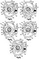
- the fluid under pressure flows through the inlet passage 82 and the inlet port 84 into the pressure chamber 48 of the pretensioner motor 40, as indicated by the arrow 92 in Fig. 5A.
- the fluid impacts upon the rotor face 50, causing the rotor 42 to rotate in a generally clockwise direction as viewed in Figs. 5A-5E.
- the rotor 42 orbits and rotates continuously within the housing 44.
- the gas pressure on the rotor face receiving the pressurized fluid from the inlet port 84 overcomes the gas pressure on the other faces of the rotor 42.
- the force of the moving rotor 42 is transmitted through its bearing surface 62 to the output shaft cam 64, causing the output shaft 66 to rotate about its axis 72.
- each one-third of a rotation of the rotor 42 results in one full rotation of the output shaft 66.
- the output shaft 66 rotates once as the rotor 42 makes one-third of a rotation during its orbiting movement from the position shown in Fig. 5A to the position shown in Fig. 5E, passing through the intermediate positions shown in Figs. 5B, 5C and 5D.
- the motor 40 is not an internal combustion motor, although it is similar in construction to the known "Wankel" engine. Rather, the pressure of the fluid supplied by the pyrotechnic device 80 into the pressure chamber 48 results in movement of the rotor 42 and consequent rotation of the output shaft 66. There is no combustion or ignition within the motor 40, other than occurs upon the actuation of the pyrotechnic device 80.
- a passage 88 similar to the inlet port 85 and the exhaust port 86, enables fluid flow between the chamber portion marked 48a in Fig. 5D and the ambient atmosphere. Thus, there is no drag-inducing compression of fluid in the chamber portion 48a.
- the output shaft 66 (Figs. 2 and 3) of the motor 40 is connected for rotation with the retractor spool 32.
- Rotation of the motor output shaft 66 caused by the orbiting and rotational movement of the rotor 42 in response to actuation of the pyrotechnic device 80, results in rotation of the retractor spool 32 in a belt retraction direction.
- belt webbing 14 is wound onto the spool. This takes slack out of the seat belt system 11, tensioning the belt webbing 14 to restrain movement of the vehicle occupant.
- the rotor 42 continues to rotate the output shaft 66.
- the pyrotechnic device 80 when actuated, supplies fluid under pressure for a finite period of time, preferably less than 30 milliseconds, rotating the retractor spool 32 in the belt retraction direction.
- the motor 40 and its output shaft 66 no longer effect rotation of the retractor spool 32 in the belt retraction direction. Withdrawal of belt webbing 14 from the retractor spool 32 must then be prevented in some other manner.
- a suitable blocking mechanism 100 is illustrated in Figs. 6-8.
- the blocking mechanism 100 includes a rod 102 slidable in a bore 104 of the housing 44.
- the rotor 42 (Fig. 6) moves relative to the housing 44 in a first direction of movement as indicated by the arrow 110.
- a moving apex of the rotor 42 as indicated by the reference numeral 112 engages the rod 102, the rod is moved outward into the housing bore 104, compressing the spring 106.
- the rotor apex 112 moves in the direction 110 past the blocking assembly 100. All of the apexes of the rotor 42 can in this manner pass the blocking mechanism 100 when the motor 40 is actuated, thereby allowing the pretensioner 10 to cause retraction of belt webbing 14.
- Figs. 9-11 illustrate a second type of blocking mechanism 120.
- the blocking mechanism 120 includes a piston 122 disposed in a secondary fluid passage 124 opening off the motor fluid inlet passage 82.
- the piston 122 is fixed for movement with a lever 126 pivotally mounted at 128 to the motor housing 44.
- the pretensioner 10 remains operable to wind belt webbing 14 onto the retractor spool 32 upon actuation of the motor 40, while the blocking mechanism 120 prevents withdrawal of belt webbing from the retractor 20 after the motor 40 has tensioned the belt webbing 14.
- Figs. 12 and 13 illustrate a third type of blocking mechanism 140.
- the blocking mechanism 140 includes a pawl 142 mounted for pivotal movement relative to the housing 44.
- An overcenter spring 144 has one end connected with the housing 44 and its other end connected with the pawl 142.
- the overcenter spring 144 normally biases the pawl 142 into a position illustrated in Fig. 12 disposed out of the pressure chamber 48.
- the pyrotechnic device 80 directs fluid under pressure through the fluid inlet passage 82. A portion of this fluid flows through an interconnected passage 146 and contacts the pawl 142. The pressure of the fluid acting on the pawl 142 moves the pawl against the biasing effect of the overcenter spring 144, into an engaged position as shown in Fig. 13. When the pawl 142 is in the engaged position, a portion of the pawl projects into the pressure chamber 48 inside the housing 44. The overcenter spring 144 resiliently holds the pawl 142 in the engaged position.
- each moving rotor apex engages the pawl 142 and moves it out of the pressure chamber 48, against the biasing effect of the overcenter spring 144, enabling the rotor to pass the pawl 142.
- the overcenter spring 144 moves the pawl back into the engaged position. This sequence repeats each time a rotor apex moves in the belt retraction direction 150 into engagement with the pawl 142.
- Rotation of the rotor 42 in a belt withdrawal direction 152 is blocked by engagement of the rotor with the engaged pawl 142, as shown in Fig. 13. This blocks rotation of the motor output shaft 66 in the same direction, and accordingly blocks rotation of the retractor spool 32 in that direction also. This blocks withdrawal of belt webbing from the retractor 20, thus continuing to restrain forward movement of the vehicle occupant relative to the vehicle seat 12.
- Figs. 14 and 15 illustrate the use of the pretensioner 10 to move a seat belt buckle 192 in a direction to tension belt webbing connected to the buckle.
- the output shaft 66 of the pretensioner 10 is fixed for rotation with a drum 194 having a spiral groove 196.
- a buckle support cable 198 is fixed by a cable end connector 200 to the drum 194.
- the output shaft 66 rotates the drum 194 in a belt tensioning direction as indicated by the arrow 202 in Fig. 14.
- the buckle support cable 198 is wound in the spiral groove 196 on the drum.
- the buckle 192 is drawn closer to the drum 194. This movement of the buckle 192 tensions belt webbing connected with the buckle 192, to restrain forward movement of a vehicle occupant.
- the output shaft 66 of the pretensioner 10 is connected for rotational movement with a web grabber 160.
- the web grabber 160 is part of a web grabber assembly 162 which is disposed in a position as illustrated schematically in Fig. 1 intermediate the shoulder belt portion 28 of the belt webbing 14 and the retractor 20.
- the web grabber assembly 162 includes a frame 164 fixed to the vehicle body 16 in a manner not shown.
- the pretensioner 10 is mounted on the frame 164.
- the web grabber 160 is supported on shafts 166 and 168 for rotation relative to the frame 164.
- the shaft 166 is coupled for rotational movement with the output shaft 66 of the pretensioner 10.
- a slot 170 in the web grabber 160 divides the web grabber into a shorter portion 172 and a longer portion 174.
- the belt webbing 14 extends through the slot 170 and the web grabber 160.
- the web grabber 160 may be coated with a soft plastic material to enhance gripping.
- Fig. 17 illustrates the web grabber assembly 162 in an unactuated condition.
- the belt webbing 14 extends vertically through the slot 170 in the web grabber 160.
- the belt webbing 14 is movable freely through the slot 170.
- the motor output shaft 66 rotates in a belt retraction direction 180 (Fig. 18).
- the web grabber 160 also rotates in the belt retraction direction 180.
- the shorter portion 172 of the web grabber draws belt webbing 182 from the retractor 20.
- the longer portion 174 of the web grabber 160 draws shoulder belt webbing 28.
- Belt webbing from the shoulder belt portion 28 of the seat belt system 11 is drawn into the web grabber assembly 162 at a faster rate than is the belt webbing 182 from the retractor 20.
- the drawing of the belt webbing 28 into the web grabber assembly 162 tensions the belt webbing about the vehicle occupant, restraining forward movement of the occupant relative to the vehicle seat 12.
- a gear drive assembly 210 transmits the output of the pretensioner 10 to the spool of the retractor 20.
- the gear drive assembly 210 includes a first spur gear 212 connected for rotation with the output shaft 66 of the pretensioner 10.
- the gear assembly 210 also includes a second spur gear 214 which meshes with the gear 212.
- the gear 214 is fixed for rotation with a shaft 216.
- the shaft 216 is coupled for rotation with the retractor spool 32 of the retractor 20.
- the rotational movement of the output shaft 66 is transmitted through the spur gears 212 and 214 to the shaft 216.
- the shaft 216 rotates the retractor spool 32 in the belt withdrawal direction. Rotation of the spool 32 in the belt withdrawal direction winds belt webbing 14 on the spool of the retractor 20. This tensions the belt webbing extended about the vehicle occupant, restraining forward movement of the vehicle occupant relative to the vehicle seat 12.
- Figs. 20 and 21 illustrate a clutch assembly 230 which can be used when it is desired that the pretensioner output shaft normally be disengaged from a retractor spool or other belt tensioning device.
- the output shaft is not fixed for rotation with the cam (as in the embodiment of Figs. 3 and 4). Instead, the clutch assembly 230 includes an output shaft 66a and cam 64a which are rotatable relative to each other. The clutch assembly 230 enables selective coupling of the output shaft 66a for rotation with the cam 64, as discussed below.
- the cam 64a has three cam surfaces 242, 244, and 246 on its inner periphery.
- a resilient deflection member 250 is frictionally coupled to the housing 44 and does not rotate relative to the housing when the clutch assembly 230 is in the disengaged condition shown in solid lines in Figs. 20 and 21.
- the deflection member 250 rotates with the cam 64a, relative to the housing 44, when the clutch assembly 230 is in the engaged condition.
- the deflection member 250 includes three pairs of axially-extending fingers 252, 254, and 256.
- the deflection member fingers 252 bias a first clutch element 262 radially outwardly against the cam surface 242.
- the deflection member fingers 254 bias a second clutch element 264 radially outwardly against the cam surface 244; and the deflection member fingers 256 bias a third clutch element 266 radially outwardly against the cam surface 246.
- the output shaft 66a has a fluted cross sectional configuration as defined by a series of axially-extending arcuate recesses 272. In the embodiment shown, the output shaft 66a has six recesses 272 spaced equally about an axis 274 of the shaft.
- the clutch assembly 230 is normally in the disengaged condition shown in solid lines in Figs. 20 and 21.
- the output shaft 66a is free to rotate within the clutch assembly 230 without engagement with any other parts of the clutch assembly. Specifically, the output shaft 66a can rotate in a belt retraction direction as indicated by the arrow 278 in Fig. 20, and in an opposite belt withdrawal direction as indicated by the arrow 280. Therefore, the output shaft 66a can be directly coupled for rotation with a spool (not shown) of a seat belt retractor, without placing unwanted drag on the retractor spool.
- the pretensioner rotor 42 orbits and rotates in the belt retraction direction 278. This orbiting movement of the rotor 42 in the belt retraction direction 278 results in movement of the cam 64a in the same direction about the axis 274.
- the output shaft 66a can rotate in the belt withdrawal direction 280.
- the deflection member 250 moves the clutch elements 262, 264, and 266 radially outward away from the output shaft 66a.
- the clutch assembly 230 thus returns to in the disengaged position shown in solid lines in Fig. 20 and 21, in which the output shaft 66a is free to rotate in either direction relative to the rotor 42.
Landscapes
- Engineering & Computer Science (AREA)
- Mechanical Engineering (AREA)
- Automotive Seat Belt Assembly (AREA)
Applications Claiming Priority (2)
| Application Number | Priority Date | Filing Date | Title |
|---|---|---|---|
| US210931 | 1980-11-28 | ||
| US08/210,931 US5485970A (en) | 1994-03-21 | 1994-03-21 | Seat belt pretensioner |
Publications (1)
| Publication Number | Publication Date |
|---|---|
| EP0673811A1 true EP0673811A1 (fr) | 1995-09-27 |
Family
ID=22784914
Family Applications (1)
| Application Number | Title | Priority Date | Filing Date |
|---|---|---|---|
| EP95300313A Withdrawn EP0673811A1 (fr) | 1994-03-21 | 1995-01-19 | Tendeur pour ceinture de sécurité |
Country Status (4)
| Country | Link |
|---|---|
| US (1) | US5485970A (fr) |
| EP (1) | EP0673811A1 (fr) |
| JP (1) | JP2620059B2 (fr) |
| CA (1) | CA2141751C (fr) |
Cited By (5)
| Publication number | Priority date | Publication date | Assignee | Title |
|---|---|---|---|---|
| FR2725672A1 (fr) * | 1994-10-14 | 1996-04-19 | Icsrd Ruckhaltesysteme Fur Fah | Dispositif d'actionnement d'un cliquet d'arret pour bloquer une bobine d'un enrouleur de ceinture de securite |
| GB2317859A (en) * | 1996-10-03 | 1998-04-08 | Autoliv Dev | Retractor reel for a safety belt |
| US5749536A (en) * | 1995-04-10 | 1998-05-12 | Trw Occupant Restraint Systems Gmbh | Coupling for torque transfer from a propellant-operated rotary drive, on a belt shaft of a seat belt retractor for tensioning a seat belt |
| WO2000040442A1 (fr) * | 1999-01-04 | 2000-07-13 | Breed Automotive Technology, Inc. | Dispositif de rappel de ceinture de securite |
| EP1396398A1 (fr) * | 2002-09-04 | 2004-03-10 | TAKATA-PETRI (Ulm) GmbH | Prétensionneur de boucle de ceinture sécurité |
Families Citing this family (15)
| Publication number | Priority date | Publication date | Assignee | Title |
|---|---|---|---|---|
| BR9506231A (pt) * | 1994-05-19 | 1997-08-12 | Trw Repa Gmbh | Aparelho para acionar rotativamente um eixo de enrolamento de um dispositivo de enrolamento automático de correia de segurança |
| CN1241507A (zh) * | 1997-10-21 | 2000-01-19 | 孙寅贵 | 使汽车安全带可控制地松弛一定长度的方法和调节机构 |
| GB9800505D0 (en) * | 1998-01-09 | 1998-03-11 | Breed Automotive Tech | Pretensioner |
| JP4189126B2 (ja) * | 1998-09-09 | 2008-12-03 | 日本発条株式会社 | シートベルトのプリテンショナ装置 |
| DE10011829C2 (de) * | 1999-03-15 | 2002-08-08 | Nhk Spring Co Ltd | Stellantrieb für ein Fahrzeuginsassenrückhaltesystem |
| US6135380A (en) * | 1999-04-07 | 2000-10-24 | Trw Vehicle Safety Systems Inc. | Seat belt webbing pretensioner |
| EP1199214B1 (fr) | 2000-10-13 | 2006-06-21 | Nhk Spring Co.Ltd. | Système de retenu avec dispositif d'anti-sousmarinage pour passager de véhicule |
| DE102005019603A1 (de) * | 2005-04-27 | 2006-11-02 | Trw Automotive Gmbh | Drehantrieb für einen Gurtstraffer |
| US7878439B2 (en) * | 2008-10-07 | 2011-02-01 | Autoliv Asp, Inc. | Retractor with pretensioner for auxiliary load limitation |
| US8165760B2 (en) * | 2009-05-05 | 2012-04-24 | Ford Global Technologies, Llc | Method and system for electronically operating a vehicle occupant seat safety restraint system |
| CN101985298A (zh) * | 2010-11-16 | 2011-03-16 | 芜湖金安世腾汽车安全系统有限公司 | 一种应用于机动车的预张紧安全带卷收器 |
| JP6145368B2 (ja) * | 2013-09-13 | 2017-06-07 | タカタ株式会社 | シートベルトリトラクタ及びシートベルト装置 |
| US9643568B2 (en) * | 2014-12-04 | 2017-05-09 | Ford Global Technologies, Llc | Seat belt retractor including pretensioner and slack remover |
| US11370389B2 (en) | 2019-10-28 | 2022-06-28 | Ford Global Technologies, Llc | Passenger restraint pretensioner |
| US11926280B2 (en) | 2019-12-31 | 2024-03-12 | Joyson Safety Systems Acquisition Llc | Seat belt pretensioner |
Citations (11)
| Publication number | Priority date | Publication date | Assignee | Title |
|---|---|---|---|---|
| DE2426845A1 (de) * | 1974-06-04 | 1976-01-02 | Volkswagenwerk Ag | Sicherheitseinrichtung fuer fahrzeuge |
| DE2460119A1 (de) * | 1974-12-19 | 1976-06-24 | Volkswagenwerk Ag | Sicherheitsgurtanordnung fuer fahrzeuge, insbesondere kraftfahrzeuge |
| DE2535380A1 (de) * | 1975-08-08 | 1977-02-10 | Bayern Chemie Gmbh Flugchemie | Schnelldreheinrichtung fuer eine gurtaufrollvorrichtung |
| FR2491340A1 (fr) * | 1980-10-06 | 1982-04-09 | Repa Feinstanzwerk Gmbh | Tendeur de rappel pour un enrouleur automatique de ceinture de securite |
| JPS6140421A (ja) * | 1984-08-01 | 1986-02-26 | Yoichi Sugita | 容積形ロ−タリ−ピストン原動機 |
| DE3531856A1 (de) * | 1985-09-06 | 1986-12-04 | Daimler-Benz Ag, 7000 Stuttgart | Sicherheitsgurtwickelautomat mit einem eine seilrolle und eine gurtwelle verbindenden kupplungshebel |
| DE3600002A1 (de) * | 1986-01-02 | 1987-07-09 | Trw Repa Gmbh | Rotations-gurtstraffer fuer sicherheitsgurte |
| GB2216778A (en) * | 1988-04-08 | 1989-10-18 | Honda Motor Co Ltd | Seat belt retractor system having seat belt tightening means |
| DE9104917U1 (de) * | 1990-04-23 | 1991-08-29 | Takata Corp., Tokio/Tokyo | Gurtstraffer für einen Sicherheitsgurt in einem Fahrzeug |
| DE4305596A1 (de) * | 1993-02-24 | 1994-02-17 | Daimler Benz Ag | Aufwickelvorrichtung für einen Sicherheitsgurt in Fahrzeugen |
| EP0648652A1 (fr) * | 1993-10-15 | 1995-04-19 | HS Technik und Design Technische Entwicklungen GmbH | Dispositif d'entraînement en rotation d'un arbre d'enroulement d'un rétracteur pour ceinture de sécurité |
Family Cites Families (14)
| Publication number | Priority date | Publication date | Assignee | Title |
|---|---|---|---|---|
| US3606378A (en) * | 1969-06-18 | 1971-09-20 | Luka Prostran | Inertial electromagnetic locking mechanism for safety belts in motor vehicles |
| DE2505626A1 (de) * | 1975-02-11 | 1976-08-19 | Volkswagenwerk Ag | Sicherheitseinrichtung fuer fahrzeuge, insbesondere kraftfahrzeuge |
| DE2510514C3 (de) * | 1975-03-11 | 1980-01-10 | Bayern-Chemie Gesellschaft Fuer Flugchemische Antriebe Mbh, 8261 Aschau | Aufwickelvorrichtung für Sicherheitsgurte mit pyrotechnisch angetriebener Schnelldreheinrichtung |
| US4151967A (en) * | 1977-06-07 | 1979-05-01 | Autoliv Ab | Device for stretching a band forming part of a safety belt for vehicles |
| DE2814550C2 (de) * | 1978-04-04 | 1986-12-04 | TRW Repa GmbH, 7077 Alfdorf | Rückstrammer mit pyrotechnischem Treibsatz für Sicherheitsgurtwickelautomaten |
| DE2931164A1 (de) * | 1979-08-01 | 1981-02-19 | Dynamit Nobel Ag | Rotationskraftelement |
| DE2946130A1 (de) * | 1979-11-15 | 1981-05-21 | Daimler-Benz Ag, 7000 Stuttgart | Gurtband-aufwickelvorrichtung zur beseitigung der gurtlose eines sicherheitsgurtsystemes |
| US4286758A (en) * | 1980-01-29 | 1981-09-01 | Toyota Jidosha Kogyo Kabushiki Kaisha | Webbing retractor |
| DE3215928C2 (de) * | 1982-04-29 | 1985-11-21 | Bayern-Chemie Gesellschaft für flugchemische Antriebe mbH, 8261 Aschau | Aufwickelvorrichtung für Sicherheitsgurte |
| DE3215929C2 (de) * | 1982-04-29 | 1985-05-02 | Bayern-Chemie Gesellschaft für flugchemische Antriebe mbH, 8261 Aschau | Aufwickelvorrichtung mit Rückstrammer für Sicherheitsgurte |
| DE3215925C2 (de) * | 1982-04-29 | 1985-11-28 | Bayern-Chemie Gesellschaft für flugchemische Antriebe mbH, 8261 Aschau | Aufwickelvorrichtung mit Rückstrammer für Sicherheitsgurte |
| US4840325A (en) * | 1986-04-02 | 1989-06-20 | Honda Giken Kogyo Kabushiki Kaisha | Seat belt tightening device |
| US4871131A (en) * | 1988-09-19 | 1989-10-03 | The Boeing Company | Ejection seat haulback system |
| US5248110A (en) * | 1991-07-17 | 1993-09-28 | Takata Corporation | Vehicle seat belt retractor |
-
1994
- 1994-03-21 US US08/210,931 patent/US5485970A/en not_active Expired - Fee Related
-
1995
- 1995-01-19 EP EP95300313A patent/EP0673811A1/fr not_active Withdrawn
- 1995-02-03 CA CA002141751A patent/CA2141751C/fr not_active Expired - Fee Related
- 1995-03-22 JP JP7063209A patent/JP2620059B2/ja not_active Expired - Fee Related
Patent Citations (11)
| Publication number | Priority date | Publication date | Assignee | Title |
|---|---|---|---|---|
| DE2426845A1 (de) * | 1974-06-04 | 1976-01-02 | Volkswagenwerk Ag | Sicherheitseinrichtung fuer fahrzeuge |
| DE2460119A1 (de) * | 1974-12-19 | 1976-06-24 | Volkswagenwerk Ag | Sicherheitsgurtanordnung fuer fahrzeuge, insbesondere kraftfahrzeuge |
| DE2535380A1 (de) * | 1975-08-08 | 1977-02-10 | Bayern Chemie Gmbh Flugchemie | Schnelldreheinrichtung fuer eine gurtaufrollvorrichtung |
| FR2491340A1 (fr) * | 1980-10-06 | 1982-04-09 | Repa Feinstanzwerk Gmbh | Tendeur de rappel pour un enrouleur automatique de ceinture de securite |
| JPS6140421A (ja) * | 1984-08-01 | 1986-02-26 | Yoichi Sugita | 容積形ロ−タリ−ピストン原動機 |
| DE3531856A1 (de) * | 1985-09-06 | 1986-12-04 | Daimler-Benz Ag, 7000 Stuttgart | Sicherheitsgurtwickelautomat mit einem eine seilrolle und eine gurtwelle verbindenden kupplungshebel |
| DE3600002A1 (de) * | 1986-01-02 | 1987-07-09 | Trw Repa Gmbh | Rotations-gurtstraffer fuer sicherheitsgurte |
| GB2216778A (en) * | 1988-04-08 | 1989-10-18 | Honda Motor Co Ltd | Seat belt retractor system having seat belt tightening means |
| DE9104917U1 (de) * | 1990-04-23 | 1991-08-29 | Takata Corp., Tokio/Tokyo | Gurtstraffer für einen Sicherheitsgurt in einem Fahrzeug |
| DE4305596A1 (de) * | 1993-02-24 | 1994-02-17 | Daimler Benz Ag | Aufwickelvorrichtung für einen Sicherheitsgurt in Fahrzeugen |
| EP0648652A1 (fr) * | 1993-10-15 | 1995-04-19 | HS Technik und Design Technische Entwicklungen GmbH | Dispositif d'entraînement en rotation d'un arbre d'enroulement d'un rétracteur pour ceinture de sécurité |
Non-Patent Citations (1)
| Title |
|---|
| PATENT ABSTRACTS OF JAPAN vol. 10, no. 196 (M - 497) 10 July 1986 (1986-07-10) * |
Cited By (8)
| Publication number | Priority date | Publication date | Assignee | Title |
|---|---|---|---|---|
| FR2725672A1 (fr) * | 1994-10-14 | 1996-04-19 | Icsrd Ruckhaltesysteme Fur Fah | Dispositif d'actionnement d'un cliquet d'arret pour bloquer une bobine d'un enrouleur de ceinture de securite |
| ES2128209A1 (es) * | 1994-10-14 | 1999-05-01 | Icsrd Ruckhaltesysteme Fur Fah | Dispositivo para el accionamiento de un trinquete de retencion para el bloqueo de un carrete de un dispositivo de enrollamiento de un cinturon de seguridad. |
| US5749536A (en) * | 1995-04-10 | 1998-05-12 | Trw Occupant Restraint Systems Gmbh | Coupling for torque transfer from a propellant-operated rotary drive, on a belt shaft of a seat belt retractor for tensioning a seat belt |
| GB2317859A (en) * | 1996-10-03 | 1998-04-08 | Autoliv Dev | Retractor reel for a safety belt |
| WO2000040442A1 (fr) * | 1999-01-04 | 2000-07-13 | Breed Automotive Technology, Inc. | Dispositif de rappel de ceinture de securite |
| US6224008B1 (en) | 1999-01-04 | 2001-05-01 | Breed Automotive Technology, Inc. | Seat belt retractor |
| EP1396398A1 (fr) * | 2002-09-04 | 2004-03-10 | TAKATA-PETRI (Ulm) GmbH | Prétensionneur de boucle de ceinture sécurité |
| US7097206B2 (en) | 2002-09-04 | 2006-08-29 | Takata-Petri (Ulm) Gmbh | Seat belt-buckle tightener |
Also Published As
| Publication number | Publication date |
|---|---|
| CA2141751C (fr) | 1998-04-07 |
| JP2620059B2 (ja) | 1997-06-11 |
| US5485970A (en) | 1996-01-23 |
| JPH07309205A (ja) | 1995-11-28 |
| CA2141751A1 (fr) | 1995-09-22 |
Similar Documents
| Publication | Publication Date | Title |
|---|---|---|
| US5485970A (en) | Seat belt pretensioner | |
| EP0641691A1 (fr) | Dispositif tendeur pour ceinture de sécurité | |
| US5899399A (en) | Seat belt pretensioner | |
| US5529258A (en) | Secondary locking mechanism for retractor with pretensioner | |
| US4483494A (en) | Seat belt retractor | |
| US5839686A (en) | Chain driven pretensioner and retractor | |
| US6318662B1 (en) | Webbing winding device | |
| EP0662408B1 (fr) | Enrouleur de boucle | |
| US6513747B1 (en) | Pretensioner integrated with a force transferring apparatus of a seat belt retractor | |
| US5697571A (en) | Chain link rack pretensioner | |
| US6702056B2 (en) | Seatbelt retractor | |
| US5782423A (en) | Spiral tube compact pretensioner and retractor | |
| US4172568A (en) | Seat belt retractor with tension eliminator | |
| GB2330334A (en) | Buckle pretensioner for a vehicle | |
| EP1504971A2 (fr) | Enrouleur de ceinture de sécurité | |
| GB2244203A (en) | Buckle pretensioner for seatbelts | |
| CN100548753C (zh) | 安全带卷张紧器 | |
| US20030047931A1 (en) | Buckle pretensioner | |
| US5775618A (en) | Tension controlled seat belt retractor | |
| US20020140278A1 (en) | Seat restraint tensioner | |
| US5507447A (en) | Seat belt retractor with cinch mechanism | |
| US5211352A (en) | Dual spring tension reducer | |
| GB2323016A (en) | Safety belt pre-tensioner | |
| JPH0453735B2 (fr) | ||
| US4518130A (en) | Lap and shoulder belt retractor |
Legal Events
| Date | Code | Title | Description |
|---|---|---|---|
| PUAI | Public reference made under article 153(3) epc to a published international application that has entered the european phase |
Free format text: ORIGINAL CODE: 0009012 |
|
| AK | Designated contracting states |
Kind code of ref document: A1 Designated state(s): BE DE ES FR GB IT NL SE |
|
| 17P | Request for examination filed |
Effective date: 19950904 |
|
| 17Q | First examination report despatched |
Effective date: 19960812 |
|
| GRAG | Despatch of communication of intention to grant |
Free format text: ORIGINAL CODE: EPIDOS AGRA |
|
| GRAG | Despatch of communication of intention to grant |
Free format text: ORIGINAL CODE: EPIDOS AGRA |
|
| GRAH | Despatch of communication of intention to grant a patent |
Free format text: ORIGINAL CODE: EPIDOS IGRA |
|
| STAA | Information on the status of an ep patent application or granted ep patent |
Free format text: STATUS: THE APPLICATION IS DEEMED TO BE WITHDRAWN |
|
| 18D | Application deemed to be withdrawn |
Effective date: 19980716 |