EP0673855A2 - Kartusche für unter Druck gesetzte Flüssigkeit - Google Patents
Kartusche für unter Druck gesetzte Flüssigkeit Download PDFInfo
- Publication number
- EP0673855A2 EP0673855A2 EP95103496A EP95103496A EP0673855A2 EP 0673855 A2 EP0673855 A2 EP 0673855A2 EP 95103496 A EP95103496 A EP 95103496A EP 95103496 A EP95103496 A EP 95103496A EP 0673855 A2 EP0673855 A2 EP 0673855A2
- Authority
- EP
- European Patent Office
- Prior art keywords
- cartridge
- container
- pressurised fluid
- chamber
- aperture
- Prior art date
- Legal status (The legal status is an assumption and is not a legal conclusion. Google has not performed a legal analysis and makes no representation as to the accuracy of the status listed.)
- Withdrawn
Links
Images

Classifications
-
- B—PERFORMING OPERATIONS; TRANSPORTING
- B65—CONVEYING; PACKING; STORING; HANDLING THIN OR FILAMENTARY MATERIAL
- B65D—CONTAINERS FOR STORAGE OR TRANSPORT OF ARTICLES OR MATERIALS, e.g. BAGS, BARRELS, BOTTLES, BOXES, CANS, CARTONS, CRATES, DRUMS, JARS, TANKS, HOPPERS, FORWARDING CONTAINERS; ACCESSORIES, CLOSURES, OR FITTINGS THEREFOR; PACKAGING ELEMENTS; PACKAGES
- B65D85/00—Containers, packaging elements or packages, specially adapted for particular articles or materials
- B65D85/70—Containers, packaging elements or packages, specially adapted for particular articles or materials for materials not otherwise provided for
- B65D85/72—Containers, packaging elements or packages, specially adapted for particular articles or materials for materials not otherwise provided for for edible or potable liquids, semiliquids, or plastic or pasty materials
- B65D85/73—Containers, packaging elements or packages, specially adapted for particular articles or materials for materials not otherwise provided for for edible or potable liquids, semiliquids, or plastic or pasty materials with means specially adapted for effervescing the liquids, e.g. for forming bubbles or beer head
Definitions
- This invention relates to a cartridge for use in conjunction with a container which is provided with contents in the form of a carbonated beverage.
- the cartridge is provided in the interior of the container and can be charged with a quantity of pressurised fluid and allows the selective release of the same into the carbonated beverage.
- the conventional cartridge is placed in the can, the can filled with the beer and the can sealed.
- the can is pasteurised and the heat of pasteurisation causes the pressure of the beer to increase and some of the beer enters the cartridge through a small aperture therein and forms the pressurised fluid.
- the can and contents are then flush cooled which reduces the pressure of the beer and creates a pressure differential between the beer in the can and the fluid in the cartridge. The differential is not sufficient to allow the pressurised fluid to leave the cartridge through the aperture so that it remains in a pressurised state relative to the beer.
- the pressure of the beer is reduced and the pressure differential between the beer and the pressurised fluid in the cartridge increase to a sufficient extent to cause the pressurised fluid to exit into the beer via the aperture in the cartridge and cause the foaming effect in the beer to occur.
- the pressurised fluid is a mixture of gas and liquid and the presence of the liquid tends to dilute the foaming effect of the pressurised fluid. Furthermore the ratio of liquid and gas in the pressurised fluid in the cartridge is only controllable by the control of the filling process and the fluid pressure.
- the cartridges are not provided with control features and therefore the performance of each cartridge cannot be easily predicted.
- cartridges of this sort can only be used in containers which have wide openings so that the cartridge can be placed into the can before the same is sealed.
- These conventional cartridges cannot be used in bottles as they cannot be passed through the neck of the bottle and, particularly in relation to plastic bottles, the bottles cannot be subjected to pasteurisation for charging of the cartridge due to the possibility of damage to the bottle due to the heat created.
- One type of cartridge is designed for use in bottles and this comprises a cartridge with an upwardly extending portion which has formed therein a neck ring.
- the neck ring In order to secure the neck ring and cartridge in position in the bottle the neck ring is expanded to contact and locate with the necked portion of the bottle. This arrangement depends upon the neck ring being retained in engagement with the neck of the bottle for the cartridge to be maintained in the correct position. If this fails the cartridge is then loose in the bottle which is undesirable.
- the aims of the present invention are to provide a cartridge for issuing a pressurised fluid into a carbonated beverage held in a container, said container provided with a cartridge which is charged with a pressurised fluid, the composition of which can be determined by the dimensions of the cartridge and which can if required be provided with engagement means which allow the cartridge to be securely located in the container.
- a still further aim is to provide a method of inserting the cartridge into a container such as a bottle.
- a cartridge adapted to contain a pressurised fluid in a chamber therein, said cartridge provided for operation in a container for a carbonated beverage and adapted for the selected release of the pressurised fluid into the beverage, said cartridge having, in a wall thereof, at least one aperture to allow the entry and/or exit of pressurised fluid into the chamber and characterised in that the aperture opens into a cavity defined by walls inside the chamber and in which there is provided an opening in connection with the chamber of the cartridge.
- a cartridge of this form allows the composition of the pressurised fluid discharged into the beverage to be predetermined by determining the position of the opening of the cavity in relation to the chamber so that, if required, only the gas portion of the pressurised fluid can exit into the cavity via the opening and into the beverage to create a maximum foaming effect or the effect can be diluted to suit by positioning the opening into the cavity to allow a quantity of pressurised liquid to be emitted along with the gas.
- the dimension of the opening into the chamber is larger than the aperture in the wall of the cartridge.
- the cartridge is substantially cylindrical in shape and the cavity depends substantially from the base of the chamber to depend substantially upwardly from the aperture in the wall so that the pressurised fluid is required to pass through the cavity when entering and exiting the chamber.
- apertures are provided in the side walls and/or the base of the cartridge.
- the cavity depends upwardly from the aperture provided in the base or side walls such that the position of the opening from the cavity into the chamber determines the composition of the pressurised fluid emitted from the cartridge in terms of proportion of liquid and gas.
- the position of the opening in the cavity is such that the same lies in the area of the chamber filled with gas only such that the pressurised fluid emitted from the cartridge is gas only.
- the opening is positioned such that it lies within the part of the chamber filled with liquid such that the pressurised fluid emitted from the cartridge comprises the liquid lying above the opening and the gas in the chamber.
- the cartridge is provided with a plurality of resilient members depending therefrom such that when the cartridge is placed in the container the members contact with the walls of the container to maintain the cartridge in the desired position therein.
- the container is a bottle with a necked opening and the members are sufficiently flexible to allow the same to be flexed inwardly to allow entry of the cartridge into the container through the necked opening.
- the members are sufficiently flexible to allow the same to be flexed inwardly to allow entry of the cartridge into the container through the necked opening.
- the cartridge is locatable on a location means formed on the container and preferably in the base thereof.
- the chamber or cavity of the cartridge may also contain a substance inserted prior to the pressurised fluid which colours and/ or flavours the beverage when introduced into the beverage along with the pressurised fluid.
- the cartridge is formed from two parts, one of which includes the cavity depending in relation with at least one aperture formed in the wall of the same.
- the at least one exit aperture for the same is sealed in a closed state.
- the aperture is sealed with a membrane applied thereover which can be gelatine based.
- the aperture is held in a sealed condition by a valve assembly provided in the cartridge.
- the said membrane or valve assembly is provided in a form such that when the pressure differential between the pressurised fluid in the cartridge and the beverage increases upon, for example, the opening of the container, the aperture is opened by either the membrane breaking or the valve moving away from the aperture or apertures.
- the cartridge can be manufactured from any suitable plastics material or alternatively from aluminium and, when manufactured from aluminium, the cartridge is of sufficient weight to allow the same to be located across the corners of a container such as a can.
- a cartridge adapted to contain a pressurised fluid, said cartridge provided in the interior of a container for a carbonated beverage and said cartridge adapted for the selected release of the pressurised fluid into the beverage from an interior chamber characterised in that the cartridge is provided with a plurality of resilient members depending therefrom such that when the cartridge is placed in the container the members contact with the walls of the container to maintain the cartridge in the desired position therein.
- resilient members on the cartridge allows the cartridge to be securely positionable in a container and, as the members are resilient they can be flexed inwardly to allow the cartridge to be placed into a container having a relatively narrow opening such as, for example, a bottle. This is not possible with most conventional cartridges.
- the container is a bottle with a necked opening and the members are sufficiently flexible and resilient to allow the same to be flexed inwardly to pass through the necked section of the bottle.
- first set of members depending upwardly from the cartridge body and a second set of members depending downwardly.
- each of the end portions of the resilient members are angled to substantially the same angle of the wall of the container on which they are to locate.
- the members are provided with sufficient resilience to exert a pushing force on the walls of the container on which they locate and furthermore the upwardly depending members prevent the cartridge from being removed from the container once the same has been inserted therein.
- the resilient members are moulded as integral parts of the cartridge body.
- a method for assembling and inserting a cartridge into a container comprising the steps of: placing a first cartridge part into a holder, loading a top cartridge part into the holder, flushing the holder with a gas, joining the top and bottom parts together to form the cartridge and moving the cartridge into the container.
- the flushing of the area with a gas such as nitrogen during the assembly of the parts of the cartridge allows the environment to be maintained in a sterile state and also allows the cartridge to be provided precharged with nitrogen as the pressurised fluid in the chamber. This negates the need for the cartridge to be only usable in cans which are pasteurised and allows the use of nitrogen which is found to give particularly strong foaming effect.
- a gas is introduced into the holder prior to the assembly of the parts and said gas acts to charge the cartridge as it is formed and the gas thereby acts as the pressurised fluid.
- the cartridge is charged during assembly and in one embodiment the gas is nitrogen.
- the cartridge can also in one embodiment be pasteurised by hot gas or liquid during the assembly process.
- the holder When the cartridge is provided with resilient location members the holder is of a size to maintain the members in an inwardly flexed condition until the cartridge has been placed in the container.
- the method of assembly is part of an automated assembly line and a plurality of holders are moved around a carousel which links with a supply of containers at at least one station to allow the insertion of the formed cartridge into the containers.
- the aperture in the cartridge is formed by laser drilling and can also, in one embodiment, be drilled in such a manner as to cause the pressurised fluid exiting therethrough to form a vortex around the container to further improve the mixing of the pressurised fluid with the contents of the container.
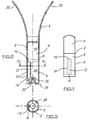
- FIG. 1 there is shown a cartridge according to a first aspect of the invention wherein said cartridge 2 comprises a first part 4 connected to a second part 6 to form the cartridge with an inner chamber 8 for the reception of pressurised fluid therein.
- the chamber 8 is connected via aperture 10 for filling and emptying of pressurised fluid therefrom.
- the aperture 10 is located in relation to a cavity 12, in this embodiment defined by walls 13, in the chamber which has an opening 16 from the cavity 12 into the chamber 8. Hence any pressurised fluid which enters or leaves the chamber 8 passes through the cavity 12.
- Figure 2 illustrates a second embodiment of the invention and uses the same reference numerals for the same features and it will be seen in this case that a plurality of apertures 10 are located on the side wall of the cartridge to allow fluid into and from the cavity 12 which in this case is defined by the side wall 14 and an inner wall 15.
- the cartridge 2 of this embodiment also includes a plurality of resilient members 20 depending upwardly therefrom which are formed as integral parts of the cartridge part 4 thereby preventing the same from becoming loosened from the cartridge and causing choking if swallowed as part of the beverage.
- the resilient members aid the location of the cartridge and these are discussed in more detail later.
- the cartridge 2 location means 22 in the form of a peg is formed in the interior of the container, the base 24 of which is shown in broken lines and onto which indent 26 formed on the cartridge 2 locates to help maintain the cartridge in the desired position in the container.
- the cartridge as shown is charged with pressurised fluid and, with the provision of the cavity 12 as shown, as the same is charged with pressurised fluid so the liquid 28 and gas 30 contents of the pressurised fluid separate as shown in Figure 2 where the cartridge is shown in a charged state.
- the foaming effect created can be controlled and predetermined by the placing of the level of the opening 14 of the cavity which in this case is shown to be near the top of the liquid level.
- the pressurised fluid upon discharge, is required to pass through the cavity and out through the apertures 10 then the liquid 28 which is below the level of the opening 14 is not discharged as it cannot get into the cavity 12.
- the pressurised fluid discharge As liquid is known to dilute the foaming effect so the position of the opening 14 can be used to determine the amount of liquid which is discharged and hence the force of the foaming effect.
- the discharge of the pressurised fluid is normally obtained when the opening of the container such as a ring pull or screw cap of a bottle is opened thereby causing an increase in pressure differential which is sufficient to cause the pressurised fluid to exit the chamber 8.
- a further feature of the cartridge of this type is that if the container is a bottle and not all of the beverage is used and the bottle is reclosed the cartridge will recharge with a pressurised fluid so that upon subsequent reopening a further foaming effect is created due to the discharge of pressurised fluid. This recharging effect can be encouraged by shaking or turning over the container.
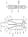
- FIG. 4 illustrates a container 102 formed of plastics PET material and having a necked opening 104 through which the cartridge 106 is required to pass to be located in the bottle.
- the cartridge 106 is formed from two parts 106a, 106b and when the same are engaged a chamber 108 is formed in which the pressurised fluid is held and the chamber has an aperture 110 which allows fluid to enter and leave the chamber when the pressure differential between the fluid in the chamber and the beverage in the container is sufficiently high.
- the cartridge 106 also includes a plurality of resilient members 112 which depend outwardly to contact the walls of the container 102 thereby maintaining the cartridge in a fixed position inside the container.
- Figure 5 illustrates the cartridge in a position ready for insertion of the same into the bottle through the necked opening 104.
- Each of the resilient members 112 is pressed inwardly toward the longitudinal axis 114 of the cartridge thereby ensuring that the circumference of the cartridge in this state is less than that of the necked opening 104.
- the cartridge 106 is placed into the bottle in this state and, once past the neck portion, the members extend toward their normal position as shown in Figure 4. As they do so the members contact the walls of the container and are held in this position pressing against the walls and holding the cartridge in position.
- the resilient members 112 are formed of plastics material and are formed of shaped outer portions 113 to add to the rigidity of the same and provide an optimum contact interface between the members and the walls of the container.
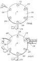
- the cartridge is formed of two parts and the first stage is to form at least one aperture in one of the parts as shown in Figure 6 wherein a carousel 202 having a plurality of work station 204-214 therearound is provided.
- a part is picked up from a hopper 216 and loaded onto the carousel in a holder and the radial orientation of the part is set at station 206 from where the part passes to station 208 where a laser drill 218 is positioned to form the aperture in the part.
- the aperture is formed the part passes to station 210 for a quality test to ensure that the aperture is properly formed and the part is then unloaded to the assembly carousel at station 212 or is rejected at station 214.
- Figure 6 shows the cartridge assembly carousel 220 which includes a plurality of work stations 222-232.
- a bottom part of the cartridge is picked up from a hopper 233 and placed in a holder which passes to station 224 where a top part of the cartridge is placed into the holder for assembly which occurs at station 226 where the holder and parts are first flushed with nitrogen and this atmosphere is maintained as the two parts are joined together hence forming a cartridge with a chamber which is precharged with a pressurised fluid in the form of nitrogen.
- the carousel is moved in relation to a bottle supply line 238.
- FIG. 7 The movement of the bottles and the movement of the cartridges is synchronised to allow a cartridge to be placed in each bottle and this position is shown in greater detail in Figure 7 where there is shown a bottle 240 positioned below a holder 242 which contains a completed cartridge therein and, at the same time acts to maintain any resilient members provided in an inwardly flexed position to allow the same to pass through the necked portion of the bottle without snagging on the same.
- the area around is maintained in a nitrogen flushed state to prevent leakage from the cartridge and ensure a sterile environment in which the cartridge is placed into the container.
- the container is then filled and sealed and an equilibrium of pressurised liquid and nitrogen occurs in the cartridge which remains until the container is opened whereupon the pressurised fluid is discharged into the beverage in the container to create the foaming effect in the same.
Landscapes
- Engineering & Computer Science (AREA)
- Mechanical Engineering (AREA)
- Containers And Packaging Bodies Having A Special Means To Remove Contents (AREA)
- Filling Or Discharging Of Gas Storage Vessels (AREA)
Applications Claiming Priority (6)
| Application Number | Priority Date | Filing Date | Title |
|---|---|---|---|
| GB9405244A GB9405244D0 (en) | 1994-03-17 | 1994-03-17 | Cartridge for containing a pressurised fluid |
| GB9405244 | 1994-03-17 | ||
| GB9409715A GB9409715D0 (en) | 1994-05-14 | 1994-05-14 | Apparatus and method relating to a cartridge containg a pressurised fluid in a container |
| GB9409715 | 1994-05-14 | ||
| GB9411532A GB9411532D0 (en) | 1994-06-09 | 1994-06-09 | Improvements relating to cartridges in beverages |
| GB9411532 | 1994-06-09 |
Publications (2)
| Publication Number | Publication Date |
|---|---|
| EP0673855A2 true EP0673855A2 (de) | 1995-09-27 |
| EP0673855A3 EP0673855A3 (de) | 1996-01-10 |
Family
ID=27267104
Family Applications (1)
| Application Number | Title | Priority Date | Filing Date |
|---|---|---|---|
| EP95103496A Withdrawn EP0673855A3 (de) | 1994-03-17 | 1995-03-10 | Kartusche für unter Druck gesetzte Flüssigkeit. |
Country Status (1)
| Country | Link |
|---|---|
| EP (1) | EP0673855A3 (de) |
Cited By (6)
| Publication number | Priority date | Publication date | Assignee | Title |
|---|---|---|---|---|
| WO1997000214A3 (en) * | 1995-06-17 | 1997-02-13 | Bass Plc | Container for pressurized liquids with foam generating device |
| EP0895938A1 (de) * | 1997-08-05 | 1999-02-10 | Schmalbach-Lubeca AG | Behälter sowie Verfahren zur Verpackung eines Produktes im Behälter |
| US8007880B2 (en) | 2002-12-16 | 2011-08-30 | Ball Packaging Europe Gmbh | Insert for a pressurized container of liquid |
| US8469221B2 (en) | 2004-07-09 | 2013-06-25 | Ball Packaging Europe Gmbh | Floating multi-chambered insert for liquid containers |
| WO2015036167A1 (de) * | 2013-09-13 | 2015-03-19 | Ball Europe Gmbh | Behälterdose und halteeinrichtung |
| US9975671B2 (en) | 2012-07-13 | 2018-05-22 | Ball Europe Gmbh | Can, holding device and method for providing a can |
Family Cites Families (8)
| Publication number | Priority date | Publication date | Assignee | Title |
|---|---|---|---|---|
| GB1266351A (de) * | 1969-01-27 | 1972-03-08 | ||
| IE70665B1 (en) * | 1989-11-22 | 1996-12-11 | Whitbread & Co Plc | Carbonated beverage container |
| WO1991013006A2 (en) * | 1990-02-21 | 1991-09-05 | E.J. Price (Developments) Limited | Drinks containers |
| GB2256628B (en) * | 1991-06-12 | 1994-12-07 | Guinness Brewing Worldwide | A beverage package and a method of forming such a package |
| GB2267882B (en) * | 1992-05-23 | 1996-03-13 | Scottish & Newcastle Plc | Packaging for beverages |
| AU4339293A (en) * | 1992-06-04 | 1993-12-30 | Edward Roger Costello | Inserts for drinks containers |
| GB9212464D0 (en) * | 1992-06-12 | 1992-07-22 | Allied Breweries Limited | Foam production |
| ATE180738T1 (de) * | 1992-12-23 | 1999-06-15 | Scottish & Newcastle Plc | Verfahren zum einbringen einer gasausstossenden kapsel in eine getränkedose mit eingezogenem halsbereich |
-
1995
- 1995-03-10 EP EP95103496A patent/EP0673855A3/de not_active Withdrawn
Cited By (11)
| Publication number | Priority date | Publication date | Assignee | Title |
|---|---|---|---|---|
| WO1997000214A3 (en) * | 1995-06-17 | 1997-02-13 | Bass Plc | Container for pressurized liquids with foam generating device |
| EP0895938A1 (de) * | 1997-08-05 | 1999-02-10 | Schmalbach-Lubeca AG | Behälter sowie Verfahren zur Verpackung eines Produktes im Behälter |
| US8007880B2 (en) | 2002-12-16 | 2011-08-30 | Ball Packaging Europe Gmbh | Insert for a pressurized container of liquid |
| US8469221B2 (en) | 2004-07-09 | 2013-06-25 | Ball Packaging Europe Gmbh | Floating multi-chambered insert for liquid containers |
| US9975671B2 (en) | 2012-07-13 | 2018-05-22 | Ball Europe Gmbh | Can, holding device and method for providing a can |
| WO2015036167A1 (de) * | 2013-09-13 | 2015-03-19 | Ball Europe Gmbh | Behälterdose und halteeinrichtung |
| CN105579361A (zh) * | 2013-09-13 | 2016-05-11 | 鲍尔欧洲有限公司 | 容器罐以及固持装置 |
| US9743786B2 (en) | 2013-09-13 | 2017-08-29 | Ball Europe Gmbh | Container can and holding device |
| AU2014320701B2 (en) * | 2013-09-13 | 2018-03-01 | Ball Europe Gmbh | Container can and holding device |
| CN105579361B (zh) * | 2013-09-13 | 2018-05-22 | 鲍尔欧洲有限公司 | 容器罐以及固持装置 |
| RU2670023C2 (ru) * | 2013-09-13 | 2018-10-17 | Болл Юроп Гмбх | Упаковочная банка и держатель |
Also Published As
| Publication number | Publication date |
|---|---|
| EP0673855A3 (de) | 1996-01-10 |
Similar Documents
| Publication | Publication Date | Title |
|---|---|---|
| EP0594221B1 (de) | Behälter für Kohlensäurehaltige Getränke | |
| US5290574A (en) | Carbonated beverage container | |
| EP0577284B1 (de) | Eine Verpackung für ein Getränk und ein Verfahren zum Verpacken eines Getränkes | |
| EP0360374B1 (de) | Verfahren zum Verpacken von Getränken und Getränkepackung | |
| EP0448200A1 (de) | Getränkeverpackung und Verfahren zum Verpacken eines gelöstes Gas enthaltenden Getränkes | |
| AU624816B2 (en) | A method of packaging a beverage | |
| EP0518522B1 (de) | Getränkebehälter mit Aufschäummitteln für das Getränk und Verfahren zur Herstellung dieses Behälters | |
| EP0481019B1 (de) | Verfahren zum abfüllen eines getränks | |
| US6896920B1 (en) | Packaging for beverage containing gas in solution | |
| AU688043B2 (en) | Venting thermoplastic container for a package with a bladder system | |
| EP0701966A2 (de) | Vorrichtung und Verfahren zum Verpacken eines Getränkes | |
| EP0610312A1 (de) | Schaumbildung durch blasendispersion | |
| GB2305159A (en) | A floating device for generating froth, a container for the device, and a method of filling the container | |
| GB2305158A (en) | A froth-generating insert for a container (e.g. a can of beer), a container incorporating the insert, and a method of filling the container |
Legal Events
| Date | Code | Title | Description |
|---|---|---|---|
| PUAI | Public reference made under article 153(3) epc to a published international application that has entered the european phase |
Free format text: ORIGINAL CODE: 0009012 |
|
| AK | Designated contracting states |
Kind code of ref document: A2 Designated state(s): AT BE CH DE DK ES FR GB GR IE IT LI LU MC NL PT SE |
|
| PUAL | Search report despatched |
Free format text: ORIGINAL CODE: 0009013 |
|
| AK | Designated contracting states |
Kind code of ref document: A3 Designated state(s): AT BE CH DE DK ES FR GB GR IE IT LI LU MC NL PT SE |
|
| 17P | Request for examination filed |
Effective date: 19960708 |
|
| STAA | Information on the status of an ep patent application or granted ep patent |
Free format text: STATUS: THE APPLICATION IS DEEMED TO BE WITHDRAWN |
|
| 18D | Application deemed to be withdrawn |
Effective date: 19971001 |