EP0674058B1 - Support de panneaux pour façade, toit, fenêtre ou porte - Google Patents
Support de panneaux pour façade, toit, fenêtre ou porte Download PDFInfo
- Publication number
- EP0674058B1 EP0674058B1 EP95810194A EP95810194A EP0674058B1 EP 0674058 B1 EP0674058 B1 EP 0674058B1 EP 95810194 A EP95810194 A EP 95810194A EP 95810194 A EP95810194 A EP 95810194A EP 0674058 B1 EP0674058 B1 EP 0674058B1
- Authority
- EP
- European Patent Office
- Prior art keywords
- profile bar
- roof
- profile bars
- bars
- roof profile
- Prior art date
- Legal status (The legal status is an assumption and is not a legal conclusion. Google has not performed a legal analysis and makes no representation as to the accuracy of the status listed.)
- Expired - Lifetime
Links
- 238000007789 sealing Methods 0.000 claims abstract description 36
- 238000001746 injection moulding Methods 0.000 claims description 2
- 229920002994 synthetic fiber Polymers 0.000 claims 1
- 239000011521 glass Substances 0.000 description 8
- 238000004519 manufacturing process Methods 0.000 description 7
- 239000004033 plastic Substances 0.000 description 4
- 229910052751 metal Inorganic materials 0.000 description 3
- 239000002184 metal Substances 0.000 description 3
- 229920002943 EPDM rubber Polymers 0.000 description 2
- 210000001503 joint Anatomy 0.000 description 2
- 239000000463 material Substances 0.000 description 2
- 229910001369 Brass Inorganic materials 0.000 description 1
- RYGMFSIKBFXOCR-UHFFFAOYSA-N Copper Chemical compound [Cu] RYGMFSIKBFXOCR-UHFFFAOYSA-N 0.000 description 1
- 229920004943 Delrin® Polymers 0.000 description 1
- 239000004952 Polyamide Substances 0.000 description 1
- 229910052782 aluminium Inorganic materials 0.000 description 1
- XAGFODPZIPBFFR-UHFFFAOYSA-N aluminium Chemical compound [Al] XAGFODPZIPBFFR-UHFFFAOYSA-N 0.000 description 1
- 239000010951 brass Substances 0.000 description 1
- 239000002131 composite material Substances 0.000 description 1
- 238000010276 construction Methods 0.000 description 1
- 229910052802 copper Inorganic materials 0.000 description 1
- 239000010949 copper Substances 0.000 description 1
- 230000001419 dependent effect Effects 0.000 description 1
- 239000005357 flat glass Substances 0.000 description 1
- 239000003365 glass fiber Substances 0.000 description 1
- 230000037431 insertion Effects 0.000 description 1
- 238000003780 insertion Methods 0.000 description 1
- 229920002647 polyamide Polymers 0.000 description 1
- 229920003051 synthetic elastomer Polymers 0.000 description 1
- 239000005061 synthetic rubber Substances 0.000 description 1
- 210000002105 tongue Anatomy 0.000 description 1
- 238000009423 ventilation Methods 0.000 description 1
- 239000002023 wood Substances 0.000 description 1
- 229910000634 wood's metal Inorganic materials 0.000 description 1
Images


Classifications
-
- E—FIXED CONSTRUCTIONS
- E04—BUILDING
- E04B—GENERAL BUILDING CONSTRUCTIONS; WALLS, e.g. PARTITIONS; ROOFS; FLOORS; CEILINGS; INSULATION OR OTHER PROTECTION OF BUILDINGS
- E04B2/00—Walls, e.g. partitions, for buildings; Wall construction with regard to insulation; Connections specially adapted to walls
- E04B2/88—Curtain walls
- E04B2/96—Curtain walls comprising panels attached to the structure through mullions or transoms
- E04B2/965—Connections of mullions and transoms
-
- E—FIXED CONSTRUCTIONS
- E04—BUILDING
- E04D—ROOF COVERINGS; SKY-LIGHTS; GUTTERS; ROOF-WORKING TOOLS
- E04D3/00—Roof covering by making use of flat or curved slabs or stiff sheets
- E04D3/02—Roof covering by making use of flat or curved slabs or stiff sheets of plane slabs, slates, or sheets, or in which the cross-section is unimportant
- E04D3/06—Roof covering by making use of flat or curved slabs or stiff sheets of plane slabs, slates, or sheets, or in which the cross-section is unimportant of glass or other translucent material; Fixing means therefor
-
- E—FIXED CONSTRUCTIONS
- E04—BUILDING
- E04D—ROOF COVERINGS; SKY-LIGHTS; GUTTERS; ROOF-WORKING TOOLS
- E04D3/00—Roof covering by making use of flat or curved slabs or stiff sheets
- E04D3/02—Roof covering by making use of flat or curved slabs or stiff sheets of plane slabs, slates, or sheets, or in which the cross-section is unimportant
- E04D3/06—Roof covering by making use of flat or curved slabs or stiff sheets of plane slabs, slates, or sheets, or in which the cross-section is unimportant of glass or other translucent material; Fixing means therefor
- E04D3/14—Roof covering by making use of flat or curved slabs or stiff sheets of plane slabs, slates, or sheets, or in which the cross-section is unimportant of glass or other translucent material; Fixing means therefor with glazing bars of other material, e.g. of glass
-
- E—FIXED CONSTRUCTIONS
- E06—DOORS, WINDOWS, SHUTTERS, OR ROLLER BLINDS IN GENERAL; LADDERS
- E06B—FIXED OR MOVABLE CLOSURES FOR OPENINGS IN BUILDINGS, VEHICLES, FENCES OR LIKE ENCLOSURES IN GENERAL, e.g. DOORS, WINDOWS, BLINDS, GATES
- E06B3/00—Window sashes, door leaves, or like elements for closing wall or like openings; Layout of fixed or moving closures, e.g. windows in wall or like openings; Features of rigidly-mounted outer frames relating to the mounting of wing frames
- E06B3/30—Coverings, e.g. protecting against weather, for decorative purposes
- E06B3/301—Coverings, e.g. protecting against weather, for decorative purposes consisting of prefabricated profiled members or glass
- E06B3/302—Covering wooden frames with metal or plastic profiled members
-
- E—FIXED CONSTRUCTIONS
- E06—DOORS, WINDOWS, SHUTTERS, OR ROLLER BLINDS IN GENERAL; LADDERS
- E06B—FIXED OR MOVABLE CLOSURES FOR OPENINGS IN BUILDINGS, VEHICLES, FENCES OR LIKE ENCLOSURES IN GENERAL, e.g. DOORS, WINDOWS, BLINDS, GATES
- E06B3/00—Window sashes, door leaves, or like elements for closing wall or like openings; Layout of fixed or moving closures, e.g. windows in wall or like openings; Features of rigidly-mounted outer frames relating to the mounting of wing frames
- E06B3/96—Corner joints or edge joints for windows, doors, or the like frames or wings
- E06B3/99—Corner joints or edge joints for windows, doors, or the like frames or wings for continuous frame members crossing each other with out interruption
-
- E—FIXED CONSTRUCTIONS
- E04—BUILDING
- E04D—ROOF COVERINGS; SKY-LIGHTS; GUTTERS; ROOF-WORKING TOOLS
- E04D3/00—Roof covering by making use of flat or curved slabs or stiff sheets
- E04D3/02—Roof covering by making use of flat or curved slabs or stiff sheets of plane slabs, slates, or sheets, or in which the cross-section is unimportant
- E04D3/06—Roof covering by making use of flat or curved slabs or stiff sheets of plane slabs, slates, or sheets, or in which the cross-section is unimportant of glass or other translucent material; Fixing means therefor
- E04D3/08—Roof covering by making use of flat or curved slabs or stiff sheets of plane slabs, slates, or sheets, or in which the cross-section is unimportant of glass or other translucent material; Fixing means therefor with metal glazing bars
- E04D2003/0843—Clamping of the sheets or glass panes to the glazing bars by means of covering strips
- E04D2003/0856—Clamping of the sheets or glass panes to the glazing bars by means of covering strips locked by screws, bolts or pins
-
- E—FIXED CONSTRUCTIONS
- E04—BUILDING
- E04D—ROOF COVERINGS; SKY-LIGHTS; GUTTERS; ROOF-WORKING TOOLS
- E04D3/00—Roof covering by making use of flat or curved slabs or stiff sheets
- E04D3/02—Roof covering by making use of flat or curved slabs or stiff sheets of plane slabs, slates, or sheets, or in which the cross-section is unimportant
- E04D3/06—Roof covering by making use of flat or curved slabs or stiff sheets of plane slabs, slates, or sheets, or in which the cross-section is unimportant of glass or other translucent material; Fixing means therefor
- E04D3/08—Roof covering by making use of flat or curved slabs or stiff sheets of plane slabs, slates, or sheets, or in which the cross-section is unimportant of glass or other translucent material; Fixing means therefor with metal glazing bars
- E04D2003/0868—Mutual connections and details of glazing bars
Definitions
- the invention relates to a plate holder according to the Preamble of claim 1, a plate holder for a facade, a roof, a window or a door.
- a plate holder is known for example from EP-A-0 369 326.
- a profile bar construction provide at least two to each other parallel, vertical, first profile bars as posts one Skeletons of a facade, which, together with them, second profile bars several arranged one above the other Limit fields that are used, for example, as windows, clear glass plates or alternately serving as windows Glass plates and opaque, plate-shaped facade elements contain.
- the invention now preferably relates to a metal one Deck profile bars composite plate bracket that has a wooden frame formed from supporting profile bars.
- the cover profile bars are preferably made of weatherproof, emoloxized or color coated Aluminum, copper or brass.
- plastic holding elements for example glass fiber reinforced polyamide formed holding elements used, which are screwed onto the supporting profile bars. On these holding elements are then clipped onto the cover profile bars or snapped into place.
- the Holding elements any elastic or rotatable tongues or have feet that have corresponding ribs, for example the free ends of a C-profile open against the holding elements, the support profile bars can reach behind.
- Such Holding elements are attached to the wood about every 10 to 50 cm, thus ensuring a secure hold of the deck profile bars is. It goes without saying that such use Holding elements must be attached exactly in a line must, since otherwise there is no deck profile bar at all can be clipped on.
- the invention is based on the object, one of several To create profile bars that can be put together, that does not have the aforementioned disadvantages.
- This task is carried out by a support and deck profile bars Composable plate holder with the characteristics of the Claim 1 solved.
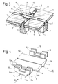
- the shown in Figures 1 and 3 and as a whole 1 designated plate holder for a multi-window Facade has one of several supporting profile bars 2 formed, cross-shaped carrier 3, on which four pairs of glass plates 4 rest.
- a first and two second cover profile bars 5 and 6 are on the support bars 2 a first and two second cover profile bars 5 and 6 releasable attached, the glass plate pairs 4 on the carrier 3rd clamp.
- the two second deck profile bars meet 6 at two opposing joints of the Flanges 5a of the first cover profile rod 5 on this.
- the Deck profile bars 5 and 6 an open to the carrier 3, angular C-profile on that through the front bar 5b or 6b and the two flanges 5a and 6a is formed.
- the deck profile bars 5 and 6 now also have two each between the two Flanges 5a and 6a arranged legs 5c and 6c, which the space between the flanges 5a and 6a into one middle channel 5d or 6d and two outer channels 5e or 6e divided.
- a sealing element 9 is arranged. This is shown in Figure 4 and in the Figures 5 and 6 together with the cover profile bar 5 and 6 respectively shown and preferably consists of a one-piece Plastic body, which is preferably completely through Injection molding has been made.
- a material for manufacturing of the sealing element 9 are particularly suitable here synthetic rubbers, such as EPDM (ethylene propylene diene monomer).
- the sealing element 9 is substantially cross-shaped and has a U-shaped first sealing part 10 and one this second sealing part 11 forming a right angle on.
- the first sealing part 10 now has two on it the second sealing part 11 projecting end portions each two cams 12 which are dimensioned and arranged in such a way that - as shown in Figure 5 - during manufacture the plate holder in the outer grooves 6e of the two at the abutting point on the first cover profile bar 5, second sealing profile bars 6 engage.
- the cams 12 additionally with at least a circumferential rib 12a may be provided, which in attached The interior walls fit more or less well of the outer channels 6e.
- the sealing element 9 sits on one another to the right Angle-forming support profile bars 2 and is at least a support profile rod 2 fastened with two screws 13.
- this is now so placed on the support profile bars 2 that the each other a right angle forming profile bars 2 with a Part between at least two, arranged parallel to each other Guide ribs 14 come to rest.
- the two gasket parts 10 and 11 at their mutually projecting edge sections provided with a bevel 10a or 11b such that the L-shaped sealing strips when manufacturing the plate holder fit into these bevels 10a and 11b and thereby in the attached state with the sealing element 9 work together in a sealing manner.
- Figure 3 also shows the support profile bars 2 arranged holding elements 15. These serve the deck profile bars 5 and 6 to be fastened to the supporting profile bars 2. They engage you with a wrench bringable screw part 16 and a in the middle groove 5d or 6d of a deck profile rod 5 or 6 determined to sit Foot 17 on.
- the latter is designed and dimensioned in such a way that it is in an insertion position of the open long side of the central channel 5d or 6d one in this existing narrowing into an extension insertable and then by turning the screw part 16 in his stop position can be brought in which he engages behind the constriction.
- FIG. 7 shows three supporting profile bars 2 fasteners belonging to them. These show one each on the outside of a first support profile bar 2 attached plate 18 and one at the end of a second support profile bar 2 sunk, for receiving the plate 18 T-slide connector 19 on.
- the support profile bar 2 with the T-slide connector 19 can be used in the manufacture of a Window frames from the inside on the first support profile bar 2 attached plate 18 can be pushed. To secure This attachment can still be done from the outside additionally a metallic pin between the plate 18 and the T-slide connector 19 are inserted, these spread apart and thereby the profile rod connection is secured.
Landscapes
- Engineering & Computer Science (AREA)
- Civil Engineering (AREA)
- Structural Engineering (AREA)
- Architecture (AREA)
- Physics & Mathematics (AREA)
- Electromagnetism (AREA)
- Securing Of Glass Panes Or The Like (AREA)
- Wing Frames And Configurations (AREA)
- Window Of Vehicle (AREA)
- Roof Covering Using Slabs Or Stiff Sheets (AREA)
Claims (7)
- Support de panneau pour façade, toit, fenêtre ou porte, avec des barres profilées porteuses (2) mutuellement assemblées et formant un angle entre elles, au moins une première barre profilée de recouvrement (5), au moins une deuxième barre profilée de recouvrement (6) formant un angle avec la première et des moyens d'étanchéité, les barres profilées porteuses (2) et les barres profilées de recouvrement (5, 6) servant à maintenir des panneaux (4) à disposer entre elles et les barres profilées de recouvrement (5, 6) étant fixées sur les barres profilées porteuses (2), et une deuxième barre profilée de recouvrement (6) aboutant, en au moins un point de joint de chaque première barre profilée de recouvrement (5), contre au moins une délimitation longitudinale de cette dernière, caractérisé en ce que chaque barre profilée de recouvrement (5, 6) possède une partie frontale (5b, 6b) et deux ailes (5a, 6a) formant conjointement avec cette dernière un profilé à section en C et se dressant vers une barre profilée porteuse (2), ainsi que deux branches (5c, 6c) qui sont disposées entre ces ailes et délimitent conjointement avec les ailes (5a, 6a) une goulotte centrale (5d, 6d) et deux goulottes extérieures (5e, 6e), et en ce que les moyens d'étanchéité comportent, en chaque point de joint d'une première barre profilée de recouvrement (5), un élément d'étanchéité (9) qui, par une partie (11), s'engage entre les deux ailes (5a) de la première barre profilée de recouvrement (5) et s'applique contre elles, et qui, par une autre partie (10), s'engage en étanchéité dans les goulottes extérieures (5e, 6e) de la ou de chaque deuxième barre profilée de recouvrement (6) aboutant contre la première barre profilée de recouvrement (5) au point de joint.
- Support de panneau selon la revendication 1, caractérisé en ce que chaque barre profilée de recouvrement (5, 6) présente une profondeur intérieure, déterminée par ses ailes (5a, 6a), qui est légèrement supérieure à la profondeur, déterminée par les deux branches (5c, 6c), de la goulotte centrale (5d, 6d).
- Support de panneau selon la revendication 1 ou 2, caractérisé en ce que l'élément d'étanchéité (9) repose sur au moins une barre profilée porteuse (2) et est fixé sur cette dernière au moyen de vis (13).
- Support de panneau selon une des revendications 1 à 3, caractérisé en ce que les moyens d'étanchéité comportent en plus des baguettes d'étanchéité (8) essentiellement en forme de L, qui peuvent être respectivement serrées entre chaque aile (5a, 6a) d'une barre profilée de recouvrement (5, 6) et un panneau (4) maintenu par les barres profilées.
- Support de panneau selon la revendication 4, caractérisé en ce que chaque baguette d'étanchéité (8) en forme de L coopère en étanchéité avec l'élément d'étanchéité (9).
- Support de panneau selon une des revendications 1 à 5, caractérisé en ce que l'élément d'étanchéité (9) est formé par un corps d'un seul tenant en matière plastique, qui a été de préférence totalement fabriqué par moulage par injection.
- Support de panneau selon une des revendications 1 à 6, des éléments de maintien (15) étant disposés sur les barres profilées porteuses (2), caractérisé en ce que chaque élément de maintien (15) présente une partie vissée (16) pouvant être engagée par une clé à écrous et un socle (17) destiné à reposer dans la goulotte centrale (5d, 6d) d'une barre profilée de recouvrement (5, 6), et en ce que le socle (17) est configuré et dimensionné de telle sorte que, lors du montage, dans une position d'introduction, il peut être introduit par le côté longitudinal ouvert de la goulotte centrale (5d, 6d) dans un élargissement en traversant un rétrécissement présent dans cette goulotte, puis, par rotation de la partie vissée (16), il peut être amené dans sa position de maintien, dans laquelle il vient en prise derrière le rétrécissement.
Applications Claiming Priority (2)
| Application Number | Priority Date | Filing Date | Title |
|---|---|---|---|
| CH879/94 | 1994-03-24 | ||
| CH87994 | 1994-03-24 |
Publications (2)
| Publication Number | Publication Date |
|---|---|
| EP0674058A1 EP0674058A1 (fr) | 1995-09-27 |
| EP0674058B1 true EP0674058B1 (fr) | 1999-05-12 |
Family
ID=4197311
Family Applications (1)
| Application Number | Title | Priority Date | Filing Date |
|---|---|---|---|
| EP95810194A Expired - Lifetime EP0674058B1 (fr) | 1994-03-24 | 1995-03-22 | Support de panneaux pour façade, toit, fenêtre ou porte |
Country Status (4)
| Country | Link |
|---|---|
| EP (1) | EP0674058B1 (fr) |
| JP (1) | JPH0842257A (fr) |
| AT (1) | ATE180030T1 (fr) |
| DE (1) | DE59505878D1 (fr) |
Families Citing this family (6)
| Publication number | Priority date | Publication date | Assignee | Title |
|---|---|---|---|---|
| KR100350789B1 (ko) | 1999-03-04 | 2002-08-28 | 엘지전자 주식회사 | 이미지 검색시스템의 분위기 칼라 자동추출 및 원래 칼라 조정방법 |
| DE10058159A1 (de) * | 2000-11-22 | 2002-05-23 | Gunvar Blanck | Thermisch trennende Fassade |
| EP1978176B1 (fr) * | 2007-03-30 | 2018-08-08 | VKR Holding A/S | Système de poutre structurel |
| JP5515186B2 (ja) * | 2012-05-07 | 2014-06-11 | ▲進▼傑▲呂▼業有限公司 | カーテンウォール |
| CN111734256B (zh) * | 2020-07-22 | 2025-05-27 | 山东等闲谷艺术粮仓文化发展有限公司 | 旋转窗户 |
| CN114396124B (zh) * | 2022-01-21 | 2023-07-11 | 陈智利 | 一种用于阳光房顶梁的连接方法 |
Family Cites Families (6)
| Publication number | Priority date | Publication date | Assignee | Title |
|---|---|---|---|---|
| DE2419462C3 (de) * | 1974-04-23 | 1980-02-14 | Alco Bauzubehoer Gmbh & Co, 3380 Goslar | Vorrichtung zum Verbinden eines Abdeckrahmens mit einem Tragrahmen von Türen oder Fenstern |
| CH580210A5 (fr) * | 1975-03-11 | 1976-09-30 | Alusuisse | |
| GB2106969B (en) * | 1981-10-03 | 1985-07-31 | Fairclough Harry | Window frames |
| US4843791A (en) * | 1987-10-29 | 1989-07-04 | The Standard Products Company | Cap fitting for gasket system intersections |
| DE3838957A1 (de) * | 1988-11-17 | 1990-05-23 | Forster Ag Hermann | Isolierende verbindungsvorrichtung fuer bauplatten |
| FR2652394B1 (fr) * | 1989-09-25 | 1992-01-03 | Pasquet Pere Fils Ets | Plot d'assemblage d'un profile sur une surface en bois. |
-
1995
- 1995-03-22 EP EP95810194A patent/EP0674058B1/fr not_active Expired - Lifetime
- 1995-03-22 AT AT95810194T patent/ATE180030T1/de not_active IP Right Cessation
- 1995-03-22 DE DE59505878T patent/DE59505878D1/de not_active Expired - Fee Related
- 1995-03-24 JP JP7066330A patent/JPH0842257A/ja active Pending
Also Published As
| Publication number | Publication date |
|---|---|
| JPH0842257A (ja) | 1996-02-13 |
| DE59505878D1 (de) | 1999-06-17 |
| EP0674058A1 (fr) | 1995-09-27 |
| ATE180030T1 (de) | 1999-05-15 |
Similar Documents
| Publication | Publication Date | Title |
|---|---|---|
| DE2811604A1 (de) | Rahmen | |
| EP0179241A2 (fr) | Panneau de construction | |
| DE4307492C2 (de) | Hohlprofil | |
| EP0674058B1 (fr) | Support de panneaux pour façade, toit, fenêtre ou porte | |
| DE3532593A1 (de) | Extrudierter kunststoffhohlprofilstab fuer rahmen von fenstern und tueren | |
| EP0182227A2 (fr) | Parclose | |
| DE102020100493A1 (de) | Torpfosten für Sichtschutz | |
| DE7732328U1 (de) | Rahmen fuer fenster, tueren u.dgl. mit metall-verblendprofil | |
| DE69827182T2 (de) | Mobile Unterkunft mit einem zu öffnenden oder nicht zu öffnenden Fenster | |
| DE69027719T2 (de) | Holzumrahmung mit einer Nut für die Verglasung | |
| EP0750089B1 (fr) | Fenêtre avec cadre de recouvrement | |
| CH655972A5 (de) | Verkleidung fuer eine in einem bauwerk befestigte zarge fuer eine zimmer- oder haustuere. | |
| DE19800130C1 (de) | Kämpfer-Verbinder für Fenster- und Türrahmen | |
| DE10134396C1 (de) | Bausatz zum Einsetzen eines Wandelementes in eine Wandöffnung einer doppelschaligen Ständerwand | |
| DE4424916A1 (de) | Profil, insbesondere Verbundprofil | |
| EP2947222B1 (fr) | Fenêtre de toit et procédé de montage d'une fenêtre de toit | |
| DE60202279T2 (de) | Rahmen zum festhalten einer plattenförmigen tafel | |
| DE3610409C2 (fr) | ||
| EP1512357A2 (fr) | Système de cloison de séparation | |
| DE29718142U1 (de) | Profilleiste | |
| DE29810510U1 (de) | Rahmenkonstruktion für ein Fenster, insbesondere ein Renovierungsfenster | |
| CH721924B1 (de) | Verfahren für die Herstellung eines Bauelements für Maueröffnungen oder Wandöffnungen in Bauwerken | |
| DE9304204U1 (de) | Rahmenprofil für Sonnen-, Licht-, Wind- und Wetterschutzvorrichtungen o.dgl. | |
| DE1534784A1 (de) | Metallrahmeanordnung,insbesondere fuer Tueren und Fenster | |
| DE9411687U1 (de) | Dichtung |
Legal Events
| Date | Code | Title | Description |
|---|---|---|---|
| PUAI | Public reference made under article 153(3) epc to a published international application that has entered the european phase |
Free format text: ORIGINAL CODE: 0009012 |
|
| AK | Designated contracting states |
Kind code of ref document: A1 Designated state(s): AT CH DE FR IT LI |
|
| 17P | Request for examination filed |
Effective date: 19960315 |
|
| GRAG | Despatch of communication of intention to grant |
Free format text: ORIGINAL CODE: EPIDOS AGRA |
|
| 17Q | First examination report despatched |
Effective date: 19980123 |
|
| GRAG | Despatch of communication of intention to grant |
Free format text: ORIGINAL CODE: EPIDOS AGRA |
|
| GRAH | Despatch of communication of intention to grant a patent |
Free format text: ORIGINAL CODE: EPIDOS IGRA |
|
| RAP1 | Party data changed (applicant data changed or rights of an application transferred) |
Owner name: ERNST SCHWEIZER AG METALLBAU |
|
| GRAH | Despatch of communication of intention to grant a patent |
Free format text: ORIGINAL CODE: EPIDOS IGRA |
|
| GRAA | (expected) grant |
Free format text: ORIGINAL CODE: 0009210 |
|
| AK | Designated contracting states |
Kind code of ref document: B1 Designated state(s): AT CH DE FR IT LI |
|
| REF | Corresponds to: |
Ref document number: 180030 Country of ref document: AT Date of ref document: 19990515 Kind code of ref document: T |
|
| ITF | It: translation for a ep patent filed | ||
| REG | Reference to a national code |
Ref country code: CH Ref legal event code: NV Representative=s name: ISLER & PEDRAZZINI AG Ref country code: CH Ref legal event code: EP |
|
| REF | Corresponds to: |
Ref document number: 59505878 Country of ref document: DE Date of ref document: 19990617 |
|
| ET | Fr: translation filed | ||
| PLBE | No opposition filed within time limit |
Free format text: ORIGINAL CODE: 0009261 |
|
| STAA | Information on the status of an ep patent application or granted ep patent |
Free format text: STATUS: NO OPPOSITION FILED WITHIN TIME LIMIT |
|
| PG25 | Lapsed in a contracting state [announced via postgrant information from national office to epo] |
Ref country code: AT Free format text: LAPSE BECAUSE OF NON-PAYMENT OF DUE FEES Effective date: 20000322 |
|
| 26N | No opposition filed | ||
| PG25 | Lapsed in a contracting state [announced via postgrant information from national office to epo] |
Ref country code: FR Free format text: LAPSE BECAUSE OF NON-PAYMENT OF DUE FEES Effective date: 20010531 |
|
| REG | Reference to a national code |
Ref country code: FR Ref legal event code: ST |
|
| PGFP | Annual fee paid to national office [announced via postgrant information from national office to epo] |
Ref country code: CH Payment date: 20040120 Year of fee payment: 10 |
|
| PGFP | Annual fee paid to national office [announced via postgrant information from national office to epo] |
Ref country code: DE Payment date: 20040224 Year of fee payment: 10 |
|
| PG25 | Lapsed in a contracting state [announced via postgrant information from national office to epo] |
Ref country code: IT Free format text: LAPSE BECAUSE OF NON-PAYMENT OF DUE FEES;WARNING: LAPSES OF ITALIAN PATENTS WITH EFFECTIVE DATE BEFORE 2007 MAY HAVE OCCURRED AT ANY TIME BEFORE 2007. THE CORRECT EFFECTIVE DATE MAY BE DIFFERENT FROM THE ONE RECORDED. Effective date: 20050322 |
|
| PG25 | Lapsed in a contracting state [announced via postgrant information from national office to epo] |
Ref country code: LI Free format text: LAPSE BECAUSE OF NON-PAYMENT OF DUE FEES Effective date: 20050331 Ref country code: CH Free format text: LAPSE BECAUSE OF NON-PAYMENT OF DUE FEES Effective date: 20050331 |
|
| PG25 | Lapsed in a contracting state [announced via postgrant information from national office to epo] |
Ref country code: DE Free format text: LAPSE BECAUSE OF NON-PAYMENT OF DUE FEES Effective date: 20051001 |
|
| REG | Reference to a national code |
Ref country code: CH Ref legal event code: PL |
|
| PG25 | Lapsed in a contracting state [announced via postgrant information from national office to epo] |
Ref country code: FR Free format text: LAPSE BECAUSE OF NON-PAYMENT OF DUE FEES Effective date: 20000331 |