EP0674072A2 - Fixation de poignées tournantes - Google Patents
Fixation de poignées tournantes Download PDFInfo
- Publication number
- EP0674072A2 EP0674072A2 EP95103218A EP95103218A EP0674072A2 EP 0674072 A2 EP0674072 A2 EP 0674072A2 EP 95103218 A EP95103218 A EP 95103218A EP 95103218 A EP95103218 A EP 95103218A EP 0674072 A2 EP0674072 A2 EP 0674072A2
- Authority
- EP
- European Patent Office
- Prior art keywords
- stop body
- cams
- fastening according
- cover
- cam
- Prior art date
- Legal status (The legal status is an assumption and is not a legal conclusion. Google has not performed a legal analysis and makes no representation as to the accuracy of the status listed.)
- Granted
Links
Images
Classifications
-
- E—FIXED CONSTRUCTIONS
- E05—LOCKS; KEYS; WINDOW OR DOOR FITTINGS; SAFES
- E05B—LOCKS; ACCESSORIES THEREFOR; HANDCUFFS
- E05B3/00—Fastening knobs or handles to lock or latch parts
- E05B3/06—Fastening knobs or handles to lock or latch parts by means arranged in or on the rose or escutcheon
-
- E—FIXED CONSTRUCTIONS
- E05—LOCKS; KEYS; WINDOW OR DOOR FITTINGS; SAFES
- E05B—LOCKS; ACCESSORIES THEREFOR; HANDCUFFS
- E05B15/00—Other details of locks; Parts for engagement by bolts of fastening devices
- E05B15/02—Striking-plates; Keepers; Bolt staples; Escutcheons
-
- E—FIXED CONSTRUCTIONS
- E05—LOCKS; KEYS; WINDOW OR DOOR FITTINGS; SAFES
- E05B—LOCKS; ACCESSORIES THEREFOR; HANDCUFFS
- E05B15/00—Other details of locks; Parts for engagement by bolts of fastening devices
- E05B15/0053—Other details of locks; Parts for engagement by bolts of fastening devices means providing a stable, i.e. indexed, position of lock parts
Definitions
- the invention relates to a rotary handle attachment according to the preamble of claim 1.
- Rotary handles are usually attached to a wing by screwing on a holding part, for example on a door leaf or on a profile.
- a stop body also known as a handle rosette
- a handle rosette which has a generally central bearing for the handle neck and is either in one piece with so-called cams or allows push-in dowels to be pushed through, for which examples can be found in DE-U-8 119 523 and in DE-A-2 940 678.
- the usual fastenings always require at least two screws, for which suitable pre-drilling must be carried out and which must not be drawn in at an angle or at an imprecise distance. This method of assembly does not require little preparatory work and involves the risk that the stop or rosette body will be blown up if the force is too great.
- an additional cover cap is necessary to cover the screw heads in many cases.
- the cams are designed as expansion dowels, while the cover is rigidly connected or integrally with stud bolts which can be pressed into the cam bores.
- the stop body is thus placed on the holding surface provided with stop holes, e.g. to the full or hollow profile of a window, whereupon the anchoring is effortlessly accomplished by simply pressing in the cover stud bolts.
- DE-B-2 056 723 already describes a fastening for door handles for which expansion anchors provided with undercut noses are used to stop against a thin door leaf.
- these are separate components that have to be inserted through a base plate and only after hooking onto the door leaf, a shield with a plug-in pin can be gripped, which snaps into place on the outside of the plate.
- the invention is characterized by captive expansion bolts and the particular simplicity of only two components to be connected.
- the cam ends are corrugated according to claim 3 on the outside, preferably with a locking profile that can be clawed into the stop bore, so that a firm dowelling takes place by spreading the cams.
- the cam bores taper conically in particular towards the cam ends, so that an expansion is carried out automatically by pressing in the preferably cylindrical stud bolts.
- the cams have at least at their ends two or more longitudinal slots, so that resilient segments are formed which claw securely in the walls of the stop bores.
- Claim 6 provides that the stud bolts connect with a preferably conical extension to the underside of the cover, so that a particularly good interlocking arises, especially if the cam bores according to claim 7 each have a shape-like or the same widening at the top of the stop body.
- the cover which is preferably provided with opposite cutouts, can be snapped onto or into a peripheral edge of the stop body. This contributes to the additional anchoring and ensures a pleasant appearance of the fitting unit. At least one recess for attaching a tool, for example by means of a To screw under the cover and pry out the screwdriver blade.
- the stud bolts according to claim 10 are substantially cylindrical and are rounded or chamfered at their free ends. This contributes significantly to easy assembly.
- the stop body consists of plastic and has supporting parts which have at least essentially uniform wall thickness. This permits material-saving production, the stop body being able to obtain high strength through suitable shaping.
- the fastening according to the invention is particularly suitable for attaching an assembly consisting of a turning handle and stop body, in which, according to claim 12, the handle neck passing through the bearing holds a square in a rotationally fixed manner and is axially fixed by a flanged ring to the stop body, which in the lower part or inside in particular next to Has cam resilient catches for circumferential engagement on or in a locking disc.
- a complete window fitting can be attached to a window sash in the simplest way and in the shortest possible time.
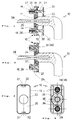
- a fitting unit partially shown in FIG. 1 consists of a window handle 10 with a handle neck 11 which is crimped to a stop body.
- the latter has a peripheral edge 13 and a bearing 14 which is located in the middle of a base plate 15.
- This is in one piece with cams 16, each of which is penetrated by a bore 18.
- the cam bores 18 each have an insertion widening 19 on the upper side of the base plate 15.
- the fitting unit also includes a cover 20 (FIG. 3) which has a hole 20 for the handle 10 - in other embodiments for the handle neck 11.
- the cover 20 can be slipped over the handle 10 and brought to the stop body 12, as shown in FIG. 1.
- the stop body 12 At the narrow ends of the stop body 12, the latter has recesses 21, to which recesses 32 of the cover 20 are assigned.
- the latter can snap into the peripheral edge 13 of the stop body 12 (FIGS. 2 and 3). If you want to snap it out, use a tool (not shown) - e.g. a screwdriver - at least on a narrow side of the recesses 21/32 in order to cause the cover 20 to be levered out.
- stud bolts 24 which are essentially cylindrical and are rounded or chamfered at the free ends 25.
- the stud bolts 24 are matched to the distances and dimensions of the cam bores 18 and can be pressed into them.
- the stud bolts 24 merge into extensions 30 which are expediently adapted to the insertion widenings 19 of the cam bores 18.
- the ends 26 of the cams 16 are provided on the outside with transverse corrugations 27 and are expandable, since the cams 16 are provided with longitudinal slots 28 at least from the ends 26 (FIG. 4), so that each cam 16 has a number - for example six - resilient Has segments. You can see the suspension through the axial adjust the depth of the longitudinal slots 28 as required; short slots result in hard suspension with little spring travel of the individual segments, whereas longer slots 28 lead to softer segment deflection.
- the cam bores 18 are preferably weakly conical in such a way that they taper towards the ends 26. Therefore, when the cover 20 is pressed in by the cylindrical stud bolts 24, an expansion takes place (FIG. 2), as a result of which the transverse corrugations 27 cling to the stop bores (not shown).
- the transverse corrugations 27 are preferably directed in a unidirectional manner, so that the cams 16 can be inserted well into such stop bores, but after the expansion by the stud bolts 24 there is a high level of dimensional resistance in the bore wall. Conventional sawtooth profiles can be provided for this.
- FIGS. 1, 2, 4 Further details of the assembly can be seen in FIGS. 1, 2, 4.
- the neck 11 of the handle 10 is axially fixed to the stop body 12 with a conveyor bush 35. This engages over a detent disk 36 with circumferential recesses, into which resilient detents 34 can fall in order to define preferred rotational positions of the handle 10.
- Two pairs of notches 34 are preferably provided at 90 ° intervals, but more and different notch arrangements can also be provided.
- the novel rotary handle attachment consists of only two components, namely a plastic stop body 12 provided with cams 16 and a cover 20 which can be connected to it are and their longitudinally slotted ends 26 spread, so that the outer locking profile 27 can claw in holding holes.
- the stop body 12 has supporting parts (base plates 15, cams 16, edge parts 17) of approximately uniform wall thickness.
- the base plate 15 supports a handle neck 11 which holds a square 38 in a rotationally fixed manner and is axially fixed to the stop body 12.
- This has resilient detents 34 at the bottom / inside for engagement on or in a locking disk 36 and outside a peripheral edge 13 for latching the cover 20; Recesses 21, 32 allow a tool to be used to pry it out.
Landscapes
- Mechanical Engineering (AREA)
- Engineering & Computer Science (AREA)
- Toys (AREA)
- Snaps, Bayonet Connections, Set Pins, And Snap Rings (AREA)
- Pens And Brushes (AREA)
- Tents Or Canopies (AREA)
- Hinges (AREA)
- Food-Manufacturing Devices (AREA)
- Domestic Plumbing Installations (AREA)
- Preparation Of Compounds By Using Micro-Organisms (AREA)
- Gripping On Spindles (AREA)
- Holding Or Fastening Of Disk On Rotational Shaft (AREA)
- Supports Or Holders For Household Use (AREA)
- Clamps And Clips (AREA)
- Dowels (AREA)
Applications Claiming Priority (2)
| Application Number | Priority Date | Filing Date | Title |
|---|---|---|---|
| DE9404851U DE9404851U1 (de) | 1994-03-22 | 1994-03-22 | Drehhandhaben-Befestigung |
| DE9404851U | 1994-03-22 |
Publications (3)
| Publication Number | Publication Date |
|---|---|
| EP0674072A2 true EP0674072A2 (fr) | 1995-09-27 |
| EP0674072A3 EP0674072A3 (fr) | 1996-01-17 |
| EP0674072B1 EP0674072B1 (fr) | 1997-07-16 |
Family
ID=6906340
Family Applications (1)
| Application Number | Title | Priority Date | Filing Date |
|---|---|---|---|
| EP95103218A Expired - Lifetime EP0674072B1 (fr) | 1994-03-22 | 1995-03-07 | Fixation de poignées tournantes |
Country Status (6)
| Country | Link |
|---|---|
| EP (1) | EP0674072B1 (fr) |
| AT (1) | ATE155545T1 (fr) |
| DE (2) | DE9404851U1 (fr) |
| DK (1) | DK0674072T3 (fr) |
| ES (1) | ES2106584T3 (fr) |
| PL (1) | PL307704A1 (fr) |
Cited By (3)
| Publication number | Priority date | Publication date | Assignee | Title |
|---|---|---|---|---|
| DE29707236U1 (de) * | 1997-04-22 | 1998-08-20 | Mayer & Co., Salzburg | Griff für Fenster oder Türen |
| EP2112301A1 (fr) * | 2008-04-26 | 2009-10-28 | ROTO FRANK Aktiengesellschaft | Rosette de poignée pour une poignée d'une armature |
| FR2988759A1 (fr) * | 2012-03-27 | 2013-10-04 | Sotralu | Ferrure en applique avec embout de dilatation d'un canon de montage |
Families Citing this family (9)
| Publication number | Priority date | Publication date | Assignee | Title |
|---|---|---|---|---|
| DE9404851U1 (de) * | 1994-03-22 | 1994-05-11 | Hoppe AG, Müstair | Drehhandhaben-Befestigung |
| DE29718935U1 (de) * | 1997-10-23 | 1998-11-19 | Mayer & Co., Salzburg | Griffanordnung |
| DE10307503A1 (de) * | 2003-02-21 | 2004-09-02 | Aug. Winkhaus Gmbh & Co. Kg | Rastmodul für Fenster- und/oder Türbeschläge |
| DE10308808A1 (de) | 2003-02-27 | 2004-09-09 | Aug. Winkhaus Gmbh & Co. Kg | Rastvorrichtung für Fenster- und/oder Türbeschläge |
| DE102005000091A1 (de) | 2005-07-19 | 2007-01-25 | Aug. Winkhaus Gmbh & Co. Kg | Antriebseinrichtung für einen Treibstangenbeschlag eines Fensters |
| PL384290A1 (pl) * | 2008-01-19 | 2009-07-20 | Janusz Urzędowski | Klamka do drzwi balkonowych i okien |
| AT12482U1 (de) * | 2011-01-31 | 2012-06-15 | Grundmann Beschlagtechnik Gmbh | Montageaufbau für abdeckbeschläge |
| EP2562330A1 (fr) * | 2011-08-26 | 2013-02-27 | ALMAR s.p.a. | Système d'armature |
| RU2625430C1 (ru) * | 2016-05-30 | 2017-07-13 | Михаил Валерьевич Прудовский | Ручка поворотная (варианты) |
Family Cites Families (6)
| Publication number | Priority date | Publication date | Assignee | Title |
|---|---|---|---|---|
| DE2056723C3 (de) * | 1970-11-18 | 1979-04-12 | Heinrich Wilke | Befestigungsvorrichtung an einem Türschild mit Handhabenlagerungsbohrang |
| DE2703139A1 (de) * | 1977-01-26 | 1978-07-27 | Grossteinbeck Gmbh Otto | Verfahren zur herstellung von leichtmetall-baubeschlagschildern |
| AT361802B (de) * | 1978-10-12 | 1981-04-10 | Grundmann Rohrbacher Schlosser | Abdeckung |
| DE8119523U1 (de) * | 1981-07-04 | 1981-09-24 | Franz Schneider Brakel GmbH & Co., 3492 Brakel | Tuer- oder fensterbeschlag |
| EP0568896B1 (fr) * | 1992-05-05 | 1997-01-08 | Siegenia-Frank Kg | Poignée de porte ou fenêtre |
| DE9404851U1 (de) * | 1994-03-22 | 1994-05-11 | Hoppe AG, Müstair | Drehhandhaben-Befestigung |
-
1994
- 1994-03-22 DE DE9404851U patent/DE9404851U1/de not_active Expired - Lifetime
-
1995
- 1995-03-07 DE DE59500374T patent/DE59500374D1/de not_active Expired - Fee Related
- 1995-03-07 ES ES95103218T patent/ES2106584T3/es not_active Expired - Lifetime
- 1995-03-07 AT AT95103218T patent/ATE155545T1/de not_active IP Right Cessation
- 1995-03-07 DK DK95103218.4T patent/DK0674072T3/da active
- 1995-03-07 EP EP95103218A patent/EP0674072B1/fr not_active Expired - Lifetime
- 1995-03-15 PL PL95307704A patent/PL307704A1/xx unknown
Cited By (3)
| Publication number | Priority date | Publication date | Assignee | Title |
|---|---|---|---|---|
| DE29707236U1 (de) * | 1997-04-22 | 1998-08-20 | Mayer & Co., Salzburg | Griff für Fenster oder Türen |
| EP2112301A1 (fr) * | 2008-04-26 | 2009-10-28 | ROTO FRANK Aktiengesellschaft | Rosette de poignée pour une poignée d'une armature |
| FR2988759A1 (fr) * | 2012-03-27 | 2013-10-04 | Sotralu | Ferrure en applique avec embout de dilatation d'un canon de montage |
Also Published As
| Publication number | Publication date |
|---|---|
| DE59500374D1 (de) | 1997-08-21 |
| ES2106584T3 (es) | 1997-11-01 |
| ATE155545T1 (de) | 1997-08-15 |
| EP0674072B1 (fr) | 1997-07-16 |
| DE9404851U1 (de) | 1994-05-11 |
| PL307704A1 (en) | 1995-10-02 |
| DK0674072T3 (da) | 1998-02-23 |
| EP0674072A3 (fr) | 1996-01-17 |
Similar Documents
| Publication | Publication Date | Title |
|---|---|---|
| DE4133478C2 (de) | Befestigungseinrichtung, insbesondere zum Befestigen einer Verkleidung an einer Unterstruktur | |
| EP0674072B1 (fr) | Fixation de poignées tournantes | |
| DE3305272C2 (fr) | ||
| EP3535824B1 (fr) | Support de jeu de barres et ensemble correspondant | |
| EP1022413A1 (fr) | Plaque de montage | |
| DE4123754C2 (de) | Kabelschelle | |
| DE3038341A1 (de) | In eine wandoeffnung eines ersten bauteils einsetzbares und ueber eine rastnut mit diesem verrastbares aufnahmeteil | |
| DE2921956A1 (de) | Befestigungsvorrichtung aus kunststoff | |
| DE8507143U1 (de) | Befestigungsvorrichtung für flächige Materialien an einer tragenden Unterlage, insbesondere für Verkleidungen in Kraftfahrzeugen | |
| WO2005073568A1 (fr) | Dispositif d'assemblage de deux profiles creux continus et son procede de fabrication | |
| DE202008005829U1 (de) | Griffrosette für einen Handgriff eines Beschlags | |
| DE202005010186U1 (de) | Halteeinrichtung sowie Halteelement hierfür | |
| EP0859091A1 (fr) | Colonne murale | |
| DE19612944A1 (de) | Verbindungsanordnung und Verbindungsverfahren | |
| EP0436795A2 (fr) | Fixation d'une poignée de porte au carré | |
| DE3335306A1 (de) | Fehlbedienungssperre fuer treibstangenbeschlaege | |
| DE29714671U1 (de) | Lochscheibe | |
| DE2553263C2 (de) | Befestigungselement zur Halterung von C-förmigen Profilen an Rahmen, Tragschienen o.dgl. | |
| WO2002030710A1 (fr) | Dispositif pour relier un support, notamment une partie de carrosserie d'une automobile, a un element en plaque, notamment a un revetement de porte ou de paroi | |
| DE19903422A1 (de) | Schließblech | |
| DE19908010C1 (de) | Befestigungsvorrichtung für Blenden oder Abdeckungen von Kraftfahrzeugen | |
| DE3034619A1 (de) | Ecklager fuer dreh-kipp-fenster, -tueren o.dgl. | |
| EP1963604A1 (fr) | Pièce coulissante pour ferrure | |
| EP0300148A1 (fr) | Plaque de base pour fixation de ski | |
| EP1128010B1 (fr) | Ferrure pour une fenêtre ou une porte |
Legal Events
| Date | Code | Title | Description |
|---|---|---|---|
| PUAI | Public reference made under article 153(3) epc to a published international application that has entered the european phase |
Free format text: ORIGINAL CODE: 0009012 |
|
| AK | Designated contracting states |
Kind code of ref document: A2 Designated state(s): AT BE CH DE DK ES FR GB IT LI LU NL SE |
|
| PUAL | Search report despatched |
Free format text: ORIGINAL CODE: 0009013 |
|
| RHK1 | Main classification (correction) |
Ipc: E05B 3/06 |
|
| AK | Designated contracting states |
Kind code of ref document: A3 Designated state(s): AT BE CH DE DK ES FR GB IT LI LU NL SE |
|
| RIN1 | Information on inventor provided before grant (corrected) |
Inventor name: ZEUS, CHRISTIAN Inventor name: WASCHGLER, MICHAEL Inventor name: ENGEL, HEINZ-ECKHARD, DR.-ING. |
|
| 17P | Request for examination filed |
Effective date: 19951206 |
|
| 17Q | First examination report despatched |
Effective date: 19960327 |
|
| GRAG | Despatch of communication of intention to grant |
Free format text: ORIGINAL CODE: EPIDOS AGRA |
|
| GRAH | Despatch of communication of intention to grant a patent |
Free format text: ORIGINAL CODE: EPIDOS IGRA |
|
| GRAH | Despatch of communication of intention to grant a patent |
Free format text: ORIGINAL CODE: EPIDOS IGRA |
|
| GRAA | (expected) grant |
Free format text: ORIGINAL CODE: 0009210 |
|
| RIN1 | Information on inventor provided before grant (corrected) |
Inventor name: ZENS, CHRISTIAN Inventor name: WASCHGLER, MICHAEL Inventor name: ENGEL, HEINZ-ECKHARD, DR.-ING. |
|
| AK | Designated contracting states |
Kind code of ref document: B1 Designated state(s): AT BE CH DE DK ES FR GB IT LI LU NL SE |
|
| REF | Corresponds to: |
Ref document number: 155545 Country of ref document: AT Date of ref document: 19970815 Kind code of ref document: T |
|
| REG | Reference to a national code |
Ref country code: CH Ref legal event code: EP |
|
| REF | Corresponds to: |
Ref document number: 59500374 Country of ref document: DE Date of ref document: 19970821 |
|
| GBT | Gb: translation of ep patent filed (gb section 77(6)(a)/1977) |
Effective date: 19970731 |
|
| ET | Fr: translation filed | ||
| ITF | It: translation for a ep patent filed | ||
| REG | Reference to a national code |
Ref country code: ES Ref legal event code: FG2A Ref document number: 2106584 Country of ref document: ES Kind code of ref document: T3 |
|
| PGFP | Annual fee paid to national office [announced via postgrant information from national office to epo] |
Ref country code: FR Payment date: 19980212 Year of fee payment: 4 |
|
| PGFP | Annual fee paid to national office [announced via postgrant information from national office to epo] |
Ref country code: LU Payment date: 19980213 Year of fee payment: 4 |
|
| PGFP | Annual fee paid to national office [announced via postgrant information from national office to epo] |
Ref country code: BE Payment date: 19980216 Year of fee payment: 4 |
|
| PGFP | Annual fee paid to national office [announced via postgrant information from national office to epo] |
Ref country code: DK Payment date: 19980217 Year of fee payment: 4 |
|
| REG | Reference to a national code |
Ref country code: DK Ref legal event code: T3 |
|
| PGFP | Annual fee paid to national office [announced via postgrant information from national office to epo] |
Ref country code: SE Payment date: 19980303 Year of fee payment: 4 |
|
| PGFP | Annual fee paid to national office [announced via postgrant information from national office to epo] |
Ref country code: ES Payment date: 19980304 Year of fee payment: 4 |
|
| PGFP | Annual fee paid to national office [announced via postgrant information from national office to epo] |
Ref country code: AT Payment date: 19980320 Year of fee payment: 4 |
|
| PGFP | Annual fee paid to national office [announced via postgrant information from national office to epo] |
Ref country code: DE Payment date: 19980417 Year of fee payment: 4 |
|
| PLBE | No opposition filed within time limit |
Free format text: ORIGINAL CODE: 0009261 |
|
| STAA | Information on the status of an ep patent application or granted ep patent |
Free format text: STATUS: NO OPPOSITION FILED WITHIN TIME LIMIT |
|
| 26N | No opposition filed | ||
| PG25 | Lapsed in a contracting state [announced via postgrant information from national office to epo] |
Ref country code: LU Free format text: LAPSE BECAUSE OF NON-PAYMENT OF DUE FEES Effective date: 19990307 Ref country code: GB Free format text: LAPSE BECAUSE OF NON-PAYMENT OF DUE FEES Effective date: 19990307 Ref country code: AT Free format text: LAPSE BECAUSE OF NON-PAYMENT OF DUE FEES Effective date: 19990307 |
|
| PG25 | Lapsed in a contracting state [announced via postgrant information from national office to epo] |
Ref country code: SE Free format text: LAPSE BECAUSE OF NON-PAYMENT OF DUE FEES Effective date: 19990308 Ref country code: ES Free format text: LAPSE BECAUSE OF NON-PAYMENT OF DUE FEES Effective date: 19990308 |
|
| PG25 | Lapsed in a contracting state [announced via postgrant information from national office to epo] |
Ref country code: LI Free format text: LAPSE BECAUSE OF NON-PAYMENT OF DUE FEES Effective date: 19990331 Ref country code: DK Free format text: LAPSE BECAUSE OF NON-PAYMENT OF DUE FEES Effective date: 19990331 Ref country code: CH Free format text: LAPSE BECAUSE OF NON-PAYMENT OF DUE FEES Effective date: 19990331 Ref country code: BE Free format text: LAPSE BECAUSE OF NON-PAYMENT OF DUE FEES Effective date: 19990331 |
|
| BERE | Be: lapsed |
Owner name: HOPPE A.G. Effective date: 19990331 |
|
| PG25 | Lapsed in a contracting state [announced via postgrant information from national office to epo] |
Ref country code: NL Free format text: LAPSE BECAUSE OF NON-PAYMENT OF DUE FEES Effective date: 19991001 |
|
| GBPC | Gb: european patent ceased through non-payment of renewal fee |
Effective date: 19990307 |
|
| EUG | Se: european patent has lapsed |
Ref document number: 95103218.4 |
|
| REG | Reference to a national code |
Ref country code: CH Ref legal event code: PL |
|
| PG25 | Lapsed in a contracting state [announced via postgrant information from national office to epo] |
Ref country code: FR Free format text: LAPSE BECAUSE OF NON-PAYMENT OF DUE FEES Effective date: 19991130 |
|
| NLV4 | Nl: lapsed or anulled due to non-payment of the annual fee |
Effective date: 19991001 |
|
| EUG | Se: european patent has lapsed |
Ref document number: 95103218.4 |
|
| REG | Reference to a national code |
Ref country code: FR Ref legal event code: ST |
|
| PG25 | Lapsed in a contracting state [announced via postgrant information from national office to epo] |
Ref country code: DE Free format text: LAPSE BECAUSE OF NON-PAYMENT OF DUE FEES Effective date: 20000101 |
|
| REG | Reference to a national code |
Ref country code: DK Ref legal event code: EBP |
|
| REG | Reference to a national code |
Ref country code: ES Ref legal event code: FD2A Effective date: 20010503 |
|
| PG25 | Lapsed in a contracting state [announced via postgrant information from national office to epo] |
Ref country code: IT Free format text: LAPSE BECAUSE OF NON-PAYMENT OF DUE FEES;WARNING: LAPSES OF ITALIAN PATENTS WITH EFFECTIVE DATE BEFORE 2007 MAY HAVE OCCURRED AT ANY TIME BEFORE 2007. THE CORRECT EFFECTIVE DATE MAY BE DIFFERENT FROM THE ONE RECORDED. Effective date: 20050307 |