EP0674086B2 - Procédé d'assemblage de vitrages isolants remplis de gaz lourd ainsi qu'un dispositif de remplissage afférent - Google Patents
Procédé d'assemblage de vitrages isolants remplis de gaz lourd ainsi qu'un dispositif de remplissage afférent Download PDFInfo
- Publication number
- EP0674086B2 EP0674086B2 EP95890063A EP95890063A EP0674086B2 EP 0674086 B2 EP0674086 B2 EP 0674086B2 EP 95890063 A EP95890063 A EP 95890063A EP 95890063 A EP95890063 A EP 95890063A EP 0674086 B2 EP0674086 B2 EP 0674086B2
- Authority
- EP
- European Patent Office
- Prior art keywords
- channel
- spacer
- glass pane
- glass panes
- plates
- Prior art date
- Legal status (The legal status is an assumption and is not a legal conclusion. Google has not performed a legal analysis and makes no representation as to the accuracy of the status listed.)
- Expired - Lifetime
Links
- 238000000034 method Methods 0.000 title claims description 16
- 239000011521 glass Substances 0.000 claims abstract description 103
- 238000007789 sealing Methods 0.000 claims abstract description 33
- 125000006850 spacer group Chemical group 0.000 claims description 32
- 230000001360 synchronised effect Effects 0.000 claims 1
- 239000000203 mixture Substances 0.000 description 4
- 238000005429 filling process Methods 0.000 description 3
- 230000000630 rising effect Effects 0.000 description 2
- 229910018503 SF6 Inorganic materials 0.000 description 1
- 230000002411 adverse Effects 0.000 description 1
- 238000010276 construction Methods 0.000 description 1
- 230000001419 dependent effect Effects 0.000 description 1
- 230000000694 effects Effects 0.000 description 1
- 238000009413 insulation Methods 0.000 description 1
- 230000002093 peripheral effect Effects 0.000 description 1
- 238000005086 pumping Methods 0.000 description 1
- SFZCNBIFKDRMGX-UHFFFAOYSA-N sulfur hexafluoride Chemical compound FS(F)(F)(F)(F)F SFZCNBIFKDRMGX-UHFFFAOYSA-N 0.000 description 1
- 229960000909 sulfur hexafluoride Drugs 0.000 description 1
Images



Classifications
-
- E—FIXED CONSTRUCTIONS
- E06—DOORS, WINDOWS, SHUTTERS, OR ROLLER BLINDS IN GENERAL; LADDERS
- E06B—FIXED OR MOVABLE CLOSURES FOR OPENINGS IN BUILDINGS, VEHICLES, FENCES OR LIKE ENCLOSURES IN GENERAL, e.g. DOORS, WINDOWS, BLINDS, GATES
- E06B3/00—Window sashes, door leaves, or like elements for closing wall or like openings; Layout of fixed or moving closures, e.g. windows in wall or like openings; Features of rigidly-mounted outer frames relating to the mounting of wing frames
- E06B3/66—Units comprising two or more parallel glass or like panes permanently secured together
- E06B3/677—Evacuating or filling the gap between the panes ; Equilibration of inside and outside pressure; Preventing condensation in the gap between the panes; Cleaning the gap between the panes
- E06B3/6775—Evacuating or filling the gap during assembly
-
- E—FIXED CONSTRUCTIONS
- E06—DOORS, WINDOWS, SHUTTERS, OR ROLLER BLINDS IN GENERAL; LADDERS
- E06B—FIXED OR MOVABLE CLOSURES FOR OPENINGS IN BUILDINGS, VEHICLES, FENCES OR LIKE ENCLOSURES IN GENERAL, e.g. DOORS, WINDOWS, BLINDS, GATES
- E06B3/00—Window sashes, door leaves, or like elements for closing wall or like openings; Layout of fixed or moving closures, e.g. windows in wall or like openings; Features of rigidly-mounted outer frames relating to the mounting of wing frames
- E06B3/66—Units comprising two or more parallel glass or like panes permanently secured together
- E06B3/673—Assembling the units
- E06B3/67365—Transporting or handling panes, spacer frames or units during assembly
- E06B3/67386—Presses; Clamping means holding the panes during assembly
-
- Y—GENERAL TAGGING OF NEW TECHNOLOGICAL DEVELOPMENTS; GENERAL TAGGING OF CROSS-SECTIONAL TECHNOLOGIES SPANNING OVER SEVERAL SECTIONS OF THE IPC; TECHNICAL SUBJECTS COVERED BY FORMER USPC CROSS-REFERENCE ART COLLECTIONS [XRACs] AND DIGESTS
- Y10—TECHNICAL SUBJECTS COVERED BY FORMER USPC
- Y10T—TECHNICAL SUBJECTS COVERED BY FORMER US CLASSIFICATION
- Y10T156/00—Adhesive bonding and miscellaneous chemical manufacture
- Y10T156/17—Surface bonding means and/or assemblymeans with work feeding or handling means
Definitions
- the invention relates to a method with the features of the introductory part of the independent claim 1.
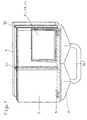
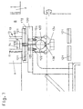
- the well-known, 1 and 2 schematically shown device consists of two plates 1 and 2, of which the plate 2 is adjustable relative to the plate 1.
- a conveyor 9 provided in the form of a roller conveyor, the one in the entire length of the lower one Edge of the plates 1 and 2 extending channel 8, above the heavy gas in the space between the plates 1 and 2 can be introduced is arranged.
- Between plates 1 and 2 is a sliding seal 31 provided.
- the outlet side (right in Fig. 1) provided seal 30 is in the space between the Plates 1 and 2 can be swiveled in.
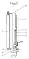
- the bottom of the adjustable plate 1 is opposite a seal 15 sealed the channel 8 (see. Fig. 2).
- the known Device is a package consisting of two Glass panes 11 and 13 and one on the glass sheet 11 attached spacer 14 (only schematic in Fig. 1 indicated) by supplied via the channel 8 Heavy gas filled, the package during the filling process stands on the conveyor 9.
- the effective length of the Channel 8 to the length of the insulating glass pane to be produced be limited by the fact that the movable Seal extends into channel 8.
- the device made known by sselling works with assembling Heavy gas filled insulating glass panes after the procedure of the introductory part of claim 1.
- the inflow of heavy gas from the channel into the package of glass panes and spacers is included the known device hindered by the roller conveyor, so that swirls arise and much Gas is consumed until the desired fill level is reached is.
- the invention has for its object a method for filling insulating glass panes with heavy gas specify that when assembling the insulating glass panes can be applied and where both for the entry of heavy gas and for that Sufficient leakage of air or air-gas mixture large cross sections are available.
- this task is performed by one Process of the type mentioned by the solved in claim 1 features.
- a gap is available which extends over the entire length of the insulating glass pane extends. Also for the escape of air or air-gas mixture there is a sufficiently large cross-section, e.g. one across from the entrance slit Extending peripheral portion of the insulating glass pane Gap available.
- Another advantage of the method according to the invention is that the size of the space between the plates that are filled with heavy gas that for the heavy gas filled insulating glass pane to be manufactured limited extent just required can be.
- the invention further relates to a device the features of the introductory part of claim 6.
- the invention relates to the device Task based on such a device Feeding heavy gas into an insulating glass pane, the is still open at least at the bottom, so there has an edge gap to improve.
- the device is also intended for performing the invention Be suitable procedure.
- that the facility to limit the effective Length of the channel is a piston that can be moved in the channel is.
- the piston By moving the piston, the length of the Range above the heavy gas into the Space enters between the two panels, in size adapted to the insulating glass pane to be produced become.
- the piston can be adjusted, for example combined with the adjustment of the sliding sealing strip become.
- This can be provided according to the invention be that the piston displaceable in the channel an approach through a slot in the channel that is sealed by a seal, protrudes with an adjusting device is coupled.
- the piston is sealed by two seals and that the seal the slot of the channel in the area between the Seals are deflected into the interior of the channel and lies radially within the approach.
- the seal the slot of the channel in the area between the Seals are deflected into the interior of the channel and lies radially within the approach.
- the shoulder protrudes from the two seals of the piston through the slot of the channel to the outside, whereby in this area (the unpressurized space between the Seals) the sealing tape from the slot to the inside is lifted off and carried out under the approach.
- An alternative embodiment is that the seal in the area of the slot of the channel a lip seal with overlapping sealing lips is.
- the way the channel connects to the room connected between the two plates is arbitrary. So several round or slit-shaped openings be provided.
- the channel is attached to the guide bar of the belt conveyor is, it can be provided that the belt conveyor two endless belts, in particular two endless toothed belts, and that the openings of the channel in the area a gap between the endless belts provided are. In this way, the openings, through which the channel with the space between the two Plates communicates between the two endless belts be extended upwards and from below something in the space between the two plates protrude.
- the belt conveyor in the area of the fixed Plate of the two plates is arranged.
- the belt conveyor and the channel connected to it transversely to the fixed plate is adjustable. This embodiment enables the at least one opening through which the channel connects the space between the two panels stands, in relation to the insulating glass pane to be filled align that the spacer frame one insulating glass pane arranged between the plates is arranged opposite.
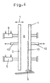
- the device shown in Figs. 3 to 6 has two essentially perpendicular, preferably over the Verticals slightly, e.g. 3 to 5 °, inclined backwards, parallel plates 1 and 2.
- the plates 1 and 2 can be the plates of a device for pressing insulating glass panes 10 his.
- the plate is 1st attached to the frame of the device.
- the plate 2 is via pressure medium cylinders 5 and 6 in the direction of the double arrow 7 slidable.
- a belt conveyor 9 is provided, on the getting up and against the for example designed as an air cushion wall, fixed to the frame Plate 1 leaning a package consisting of two glass panes 11 and 13 and a spacer 14 in the Room 8 can be funded.
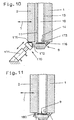
- the sealing strip 170 is used by at least two Pressure medium cylinders 171 worn and carries on their the lower edge of plate 2 and the guide bar 172, on which the upper run 173 of the belt conveyor 9 an elongated seal 175 slides on the opposite side.
- the seal 175 is in the embodiment shown in FIG. 10 formed and exists as a hose seal for example made of elastically deformable plastic. The seal can be used to increase the sealing effect 175, as soon as the sealing strip 170 in its operative position, in the the seal 175 at the bottom of the adjustable Plate 2 and against the guide bar 172, under Pressure.
- the guide bar 172 of the belt conveyor 9 is on its side opposite the sealing strip 170 continuously, for example via a bar 176, with the fixed plate 1 connected, so that there too a gas-tight seal is guaranteed.
- an elastically deformable sealing tab 180 is provided, which is when the movable plate is pushed forward 2 on the arranged below the movable plate 2 Edge of the guide bar 172 of the belt conveyor 9 creates.
- the sealing tab 180 shown in FIG. 11 can also be designed as an inflatable hose seal.
- fixed plate 1 For loading the air cushion wall, fixed plate 1 is this with a connection 12 equipped for supplying compressed air.
- the sealing device 30 arranged on the outlet side is in the embodiment of the device shown in Fig. 12 at their upper and lower ends, respectively attached to an arm 107, which is via a pair of parallelogram links 108, 109, in the machine frame is pivotally mounted, is worn.
- a Pressure cylinder 110 provided on a lever 111 attacks.
- the lever 111 is one of the two connecting link 109 arranged one above the other Shaft 112 non-rotatably connected.
- Fig. 12 it is shown that the sealing device 30 in their operative position not on the vertical outlet side Edges of the insulating glass pane 10, but at the vertical edges 105 and 106 of the plates 1 and 2 abuts.
- the second sealing device 31 is in the device in the direction of the double arrow in Fig. 3.
- the sealing device 30 and / or the sealing device 31 can in a modified embodiment also be arranged on the sliding plate 2.
- a channel 122 is provided, from which Heavy gas as symbolized by arrows 156, 157 the belt conveyor 9 flows from below into the room 8.
- the effective length of channel 122 is determined by a piston 130 to the length of the insulating glass pane 10 limited.
- Channel 122 shown for supplying heavy gas.
- channel 122 is below the Carrier 120 for the guide bar 172 of the longitudinally Belt conveyor 9 (in the example two endless toothed belts 121) attached.
- boreholes 124 go out with holes 125 in Align carrier 120 and finally to pipe sections 126 cause the gap between the two timing belts Push 121 of the belt conveyor 9 through.
- the pipe pieces 126 open in room 8 between plates 1 and 2 and especially between the two panes of glass 11 and 13 of the insulating glass pane which has not yet been completed 10 and are aligned so that they the spacer 14 are opposite.
- bores 124, 125 and the raw pieces 126 via which the interior 123 of the channel 122 the space 8 between the plates 1 and 2 in connection stands, can also be a series of longitudinal slots be provided.
- the interior 123 of the channel 122 is over a Connection line (not shown) with a source for Heavy gas (rare gas, sulfur hexafluoride or the like) in Connection.
- a source for Heavy gas rare gas, sulfur hexafluoride or the like
- the piston 130 through which the effective length of the Interior 123 of the channel 122 on the horizontal Direction of measured length of the insulating glass pane 10 can be adjusted is opposite channel 122 sealed by two seals 131. Through a Longitudinal slot 134 in the opposite of the holes 124 A portion of channel 122 protrudes 135, which is connected to the piston 130, to the outside. Via this approach 135, the piston 130 can Channel 122 can be adjusted.
- the slot 134 in the channel 122 is through a seal 136 sealed in the area of the piston 130, i.e. in the area between the two seals 131 (depressurized space) redirected inwards and under approach 135 is performed. That way the piston 130 can be adjusted as desired without the Tightness of the channel 122 to the outside through the Slot 134 is affected.
- the piston be adjusted 130 via its approach 135 with the adjustment of the movable Seal 31 is combined.
- the device works, for example, as follows: For example in the one from AT 370 201 B or the device known from AT 370 706 B or by hand from compiled package of glass panes 11 and 13 and a spacer 14, one of which is a sheet of glass 13 below from the one to the other glass pane 11 attached spacers 14 a distance (gap 60) and on the other glass pane 11 attached spacer 14 only in the upper Area rests so that the bottom and partially on the vertical Edges of the glass panes 11 and 13 an access is present in the interior of the package the belt conveyor 9 rising into space 8 between promoted the plates 1 and 2 until you, referred on the conveying direction (arrow 25) more front, more vertical Edge next to the advanced or swung-in Sealing device 30 is located. Now the second sealing device 31 in room 8 between the two plates 1 and 2 moved until they are next to, based on the Conveying direction (arrow 25) rear, vertical edge of the Insulating glass pane 10 lies.
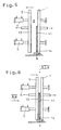
- the device according to the invention (cf. Fig. 4 to 6) can also be worked so that during the filling process, the one glass pane 13 on the movable Plate 2 entirely at a distance from the another glass pane 11 attached spacer 14 is held.
- the Plate 2 is set up for holding the glass pane 13.
- the plate 2 in its space 8 between the plates 1 and 2 facing surface Have openings through a line 12 'with negative pressure are applied to the glass pane 13 hold.
- an insulating glass pane filled with heavy gas 10 is a first glass sheet 13 on the Plate 1 leaning and supported by the conveyor belt 9 below in space 8 between plates 1 and 2 into one predetermined end position moves (Fig. 4).
- the Plate 1 be designed as an air cushion wall and it will you when transporting the glass sheet 13 via a connecting line 12 compressed air supplied.
- the adjustable plate 2 is advanced, until they turned towards plate 1 Surface rests on the glass pane 13. Once that is achieved is the plate 2, which at its 8th between the plates 1 and 2 facing side openings has, via a line 12 'with negative pressure charged and at most until then via the line 12 applied to the plate 1 vacuum (for Holding the glass sheet 13 in the predetermined End position) canceled.
- the plate 2 is with the her captured glass sheet 13 in that shown in Fig. 5 Position moved back.
- the next step is the second glass plate 11 with a spacer 14 attached to it in the Space 8 between the plates 1 and 2 up to the predetermined End position transported.
- the actual gas exchange can begin be, in which 9 heavy gas through the belt conveyor initiated and withdrawn air or air-gas mixture is, the withdrawal of air or air-gas mixture can be supported by pumping.
- the Heavy gas supply interrupted.
- the insulating glass panel 10 can also be the same be pressed. Possible constructions for such Press and drive to move the moving Press plate 2 are in DE 31 30 645 Al and AT-A 2956/87, published on June 15, 1990 described.
- the drives described there rack and pinion drives or spindle drives) instead of the pressure medium cylinders 5 and 6.
- the movable Plate 2 moved away from plate 1 and the Completely pressed insulating glass pane filled with heavy gas 10, consisting of the two glass panes 11 and 13 and the spacer inserted between them 14, the belt conveyor 9 becomes, for example Sealing station transported.
Landscapes
- Engineering & Computer Science (AREA)
- Civil Engineering (AREA)
- Structural Engineering (AREA)
- Securing Of Glass Panes Or The Like (AREA)
- Joining Of Glass To Other Materials (AREA)
- Laminated Bodies (AREA)
- Filling Or Discharging Of Gas Storage Vessels (AREA)
Claims (14)
- Procédé d'assemblage de vitrages isolants (10) remplis avec un gaz lourd, selon lequel on dispose essentiellement debout verticalement entre des plaques (1, 2) un paquet formé d'une première vitre (13), d'une seconde vitre (11) et d'un intercalaire (14) appliqué sur la seconde vitre (11), un accès (60) en forme de fente à la chambre formée entre les vitres (11, 13) du paquet existant entre l'intercalaire (14) et la première vitre (13), au moins dans la région du bord inférieur du paquet formé des vitres (11, 13) et de l'intercalaire (14), selon lequel il est prévu à côté du paquet formé des vitres (11, 13) et de l'intercalaire (14) des dispositifs d'étanchéité (30, 31) orientés essentiellement verticalement, selon lequel on introduit dans la chambre formée entre les vitres (11, 13) du gaz lourd provenant d'un canal (122) disposé en-dessous des vitres (11, 13) et selon lequel, après avoir rempli de gaz lourd (40) la chambre formée entre les vitres (11, 13), on applique l'une des vitres (13) sur l'intercalaire (14) appliqué sur l'autre vitre (11), caractérisé en ce que l'on ferme de manière étanche, à l'aide d'un joint (9), le bord inférieur horizontal du paquet formé des vitres (11,13) et de l'intercalaire (14) et en ce que l'on introduit le gaz lourd en plusieurs points, par le bord inférieur fermé de manière étanche du paquet formé des vitres (11, 13) et de l'intercalaire (14) par des ouvertures (124) situées exclusivement en vis-à-vis de l'intercalaire (14), par l'intermédiaire de lesquelles la chambre formée entre les vitres (11, 13) communique avec le canal (122).
- Procédé selon la revendication 1, caractérisé en ce que l'on ferme de manière étanche, au niveau de son bord inférieur, le paquet formé des vitres (11, 13) et de l'intercalaire (14) à l'aide d'un dispositif de transport se présentant sous la forme d'une bande transporteuse (9) et en ce que l'on introduit le gaz lourd à travers la bande transporteuse (9).
- Procédé selon la revendication 1 ou 2, caractérisé en ce que l'on déplace les vitres (11, 13) jusque dans le voisinage immédiat de l'un des dispositifs d'étanchéité (30) et en ce que l'on déplace l'autre dispositif d'étanchéité (31) en direction des vitres (11, 13).
- Procédé selon une des revendications 1 à 3, caractérisé en ce que l'on transporte la première vitre (13) jusque devant l'un des joints (30), en ce que l'on éloigne ladite vitre (13) du plan de transport, perpendiculairement à son plan, en ce que l'on amène une seconde vitre (11) avec un intercalaire (14) appliqué sur celle-ci dans une position de recouvrement avec la première vitre (13) et en ce que l'on déplace la première vitre (13) en direction de la seconde vitre (11) jusque dans une position juste devant l'intercalaire (14).
- Procédé selon une des revendications 1 à 3, caractérisé en ce que l'on amène dans l'espace (8) entre les plaques (1, 2) un paquet formé de deux vitres (11, 13) et de l'intercalaire (14), dont la première vitre (13), dans sa partie supérieure, est en contact avec l'intercalaire (14) et dans sa partie inférieure est éloignée (espace 60) de l'intercalaire (14).
- Dispositif pour l'assemblage de vitrages isolants (10) remplis avec un gaz lourd, avec disposées des deux côtés des vitres (11, 13) du vitrage isolant (10), deux plaques (1, 2) essentiellement verticales, parmi lesquelles une plaque (2) au moins peut être déplacée transversalement à son plan par rapport à l'autre plaque (1), avec deux dispositifs d'étanchéité (30, 31) qui, dans leur position de travail, sont disposés à côté de deux bords en vis-à-vis des vitres (11, 13) du vitrage isolant (10), avec un dispositif de transport (9) disposé dans la région du bord inférieur horizontal des plaques (1, 2) et avec un canal (122) qui communique par l'intermédiaire des ouvertures (124) avec l'espace (8) entre les plaques (1,2), en tant que dispositif d'amenée de gaz lourd à travers une fente (60) prévue au niveau du bord inférieur du vitrage isolant (10) entre l'une des vitres (13) et un intercalaire (14) appliqué sur l'autre vitre (11), un dispositif (130) étant prévu pour limiter la longueur active de l'espace intérieur du canal (122) à la longueur du vitrage isolant (10) mesurée dans la direction de la longueur du canal (122), caractérisé en ce que le dispositif de transport est une bande transporteuse (9) et en ce que les ouvertures (124) par l'intermédiaire de lesquelles le canal (122) communique avec l'espace (8) entre les plaques (1, 2) traversent la bande transporteuse (9) vers le haut et sont disposée exclusivement en vis-à-vis de l'intercalaire (14),
- Dispositif selon la revendication 6, caractérisé en ce que le dispositif pour limiter la longueur active du canal (122) est un piston (130) qui peut être déplacé à l'intérieur du canal (122).
- Dispositif selon la revendication 7, caractérisé en ce que le piston (130) mobile à l'intérieur du canal (122) est couplé à dispositif de réglage par l'intermédiaire d'un bossage (135) qui fait saillie à travers une fente (134) du canal (122), fermée de manière étanche par un joint (136).
- Dispositif selon la revendication 8, caractérisé en ce que le joint dans la région de la fente (124) du canal (122) est un joint à lèvres avec des lèvres d'étanchéité qui se chevauchent mutuellement.
- Dispositif selon la revendication 8, caractérisé en ce que l'étanchéité du piston (130) est réalisée par deux joints (131) et en ce que le joint (136) de la fente (134) du canal (122), dans la région entre les joints (131), est dévié en direction de la chambre intérieure (13) du canal (122) et est situé radialement à l'intérieur du bossage (135).
- Dispositif selon la revendication 6, caractérisé en ce que les ouvertures sont des ouvertures en forme de fentes.
- Dispositif selon une des revendications 6 à 11, caractérisé en ce que la bande transporteuse (9) comporte deux courroies sans fin (121), notamment des courroies sans fin crantées, et en ce que les ouvertures (124) du canal (122) sont aménagées dans la région d'un espace entre les courroies sans fin (121).
- Dispositif selon une des revendications 6 à 12, caractérisé en ce que la bande transporteuse (9) est disposée dans la région de la plaque (1) fixe.
- Dispositif selon la revendication 13, caractérisé en ce que la bande transporteuse (9) et le canal (122) communiquant avec celle-ci peuvent être déplacés transversalement à la plaque (1) fixe.
Applications Claiming Priority (12)
| Application Number | Priority Date | Filing Date | Title |
|---|---|---|---|
| AT63194A AT409128B (de) | 1994-03-24 | 1994-03-24 | Verfahren zum zusammenbauen von isolierglasscheiben, deren innenraum mit einem schwergas gefüllt ist |
| AT62894A AT404132B (de) | 1994-03-24 | 1994-03-24 | Vorrichtung zum füllen von isolierglasscheiben mit füllgas |
| AT62894 | 1994-03-24 | ||
| AT63194 | 1994-03-24 | ||
| AT628/94 | 1994-03-24 | ||
| AT631/94 | 1994-03-24 | ||
| AT120494 | 1994-06-17 | ||
| AT1204/94 | 1994-06-17 | ||
| AT120494A AT405932B (de) | 1994-06-17 | 1994-06-17 | Vorrichtung zum herstellen von mit füllgas gefüllten isolierglasscheiben |
| AT1749/94 | 1994-09-13 | ||
| AT174994A AT409263B (de) | 1994-09-13 | 1994-09-13 | Vorrichtung zum füllen von isolierglasscheiben mit füllgas |
| AT174994 | 1994-09-13 |
Publications (3)
| Publication Number | Publication Date |
|---|---|
| EP0674086A1 EP0674086A1 (fr) | 1995-09-27 |
| EP0674086B1 EP0674086B1 (fr) | 1998-05-20 |
| EP0674086B2 true EP0674086B2 (fr) | 2004-08-18 |
Family
ID=27421294
Family Applications (3)
| Application Number | Title | Priority Date | Filing Date |
|---|---|---|---|
| EP95890063A Expired - Lifetime EP0674086B2 (fr) | 1994-03-24 | 1995-03-22 | Procédé d'assemblage de vitrages isolants remplis de gaz lourd ainsi qu'un dispositif de remplissage afférent |
| EP95890061A Expired - Lifetime EP0674085B1 (fr) | 1994-03-24 | 1995-03-22 | Dispositif pour remplir des vitrages isolants avec un gaz lourd |
| EP95890064A Expired - Lifetime EP0674087B1 (fr) | 1994-03-24 | 1995-03-22 | Dispositif de fabrication de vitrages isolants remplis de gaz lourd |
Family Applications After (2)
| Application Number | Title | Priority Date | Filing Date |
|---|---|---|---|
| EP95890061A Expired - Lifetime EP0674085B1 (fr) | 1994-03-24 | 1995-03-22 | Dispositif pour remplir des vitrages isolants avec un gaz lourd |
| EP95890064A Expired - Lifetime EP0674087B1 (fr) | 1994-03-24 | 1995-03-22 | Dispositif de fabrication de vitrages isolants remplis de gaz lourd |
Country Status (6)
| Country | Link |
|---|---|
| US (3) | US5676782A (fr) |
| EP (3) | EP0674086B2 (fr) |
| JP (3) | JPH0840755A (fr) |
| AT (3) | ATE166419T1 (fr) |
| DE (8) | DE59502206D1 (fr) |
| ES (3) | ES2117379T5 (fr) |
Cited By (2)
| Publication number | Priority date | Publication date | Assignee | Title |
|---|---|---|---|---|
| EP2093370A2 (fr) | 2008-02-20 | 2009-08-26 | For El Base- Di Davanzo Nadia & C.S.N.C. | Dispositif automatique pour le remplissage d'unités de vitrage isolant et procédé correspondant |
| US8905085B2 (en) | 2011-09-09 | 2014-12-09 | Erdman Automation Corporation | Apparatus for edge sealing and simultaneous gas filling of insulated glass units |
Families Citing this family (40)
| Publication number | Priority date | Publication date | Assignee | Title |
|---|---|---|---|---|
| US6216751B1 (en) | 1997-10-24 | 2001-04-17 | Cardinal Ig Company | Method of reliably detecting seal failures |
| US5957169A (en) * | 1997-10-24 | 1999-09-28 | Cardinal Ig Company | Apparatus and method for filling insulated glass units with insulating gas |
| AT407552B (de) | 1999-06-22 | 2001-04-25 | Lisec Peter | Vorrichtung zum zusammenbauen von isolierglasscheiben, deren innenraum mit einem schwergas gefüllt ist |
| US6916392B2 (en) | 2001-06-21 | 2005-07-12 | Cardinal Ig Company | Producing and servicing insulating glass units |
| US6606837B2 (en) | 2001-08-28 | 2003-08-19 | Cardinal Ig | Methods and devices for simultaneous application of end sealant and sash sealant |
| US6804924B2 (en) * | 2001-10-12 | 2004-10-19 | Cardinal Ig Company | Repair of insulating glass units |
| US20030085238A1 (en) * | 2001-11-06 | 2003-05-08 | Segro Bradley A | Apparatus for dosing liquid gas into a multipane gas unit |
| US6793971B2 (en) | 2001-12-03 | 2004-09-21 | Cardinal Ig Company | Methods and devices for manufacturing insulating glass units |
| EP1450001B1 (fr) | 2003-02-22 | 2004-11-17 | Tecnopat AG | Dispositif d'assemblage de vitrages isolants, remplis de gaz lourd |
| DE102004009858B4 (de) * | 2004-02-25 | 2006-05-04 | Karl Lenhardt | Verfahren zum Positionieren von Glastafeln in einer vertikalen Zusammenbau- und Pressvorrichtung für Isolierglasscheiben |
| DE102004009860B4 (de) * | 2004-02-25 | 2006-05-04 | Karl Lenhardt | Verfahren und Vorrichtung zum Zusammenbauen von Isolierglasscheiben, die mit einem von Luft verschiedenen Gas gefüllt sind |
| DE102004032435B4 (de) * | 2004-07-05 | 2006-12-21 | Lenhardt Maschinenbau Gmbh | Verfahren und Vorrichtung zum Zusammenbauen von Isolierglasscheiben, die mit einem von Luft verschiedenen Gas gefüllt sind. |
| DE102004032436A1 (de) * | 2004-07-05 | 2006-02-16 | Lenhardt Maschinenbau Gmbh | Vorrichtung zum Zusammenbauen von Isolierglasscheiben, die mit einem von Luft verschiedenen Gas gefüllt sind. |
| DE102005033040B3 (de) * | 2005-07-15 | 2007-03-22 | Lenhardt Maschinenbau Gmbh | Vorrichtung zum Zusammenbauen von Isolierglasscheiben, die mit einem von Luft verschiedenen Gas gefüllt sind |
| DE102005044861B3 (de) * | 2005-09-13 | 2007-02-15 | Lenhardt Maschinenbau Gmbh | Verfahren und Vorrichtung zum Füllen von Isolierglasscheiben mit einem von Luft verschiedenen Gas |
| DE102006018333A1 (de) * | 2006-04-19 | 2007-10-25 | Karl Lenhardt | Vorrichtung zum Zusammenbauen von Insolierglasscheiben, die mit einem von Luft verschiedenen Gas gefüllt sind |
| CN101918667A (zh) | 2007-11-13 | 2010-12-15 | 无限尖端科技有限责任公司 | 具有侧壁的箱式间隔装置 |
| DE202008008117U1 (de) * | 2008-06-19 | 2009-10-29 | Bc Prozesstechnik Gmbh | Vorrichtung zur Aufnahme und zum Transport von Profilen und flächigen Elementen |
| US8181400B2 (en) * | 2009-05-12 | 2012-05-22 | Kindschuh Rodney G | Gas fill device for multiple pane windows |
| US8586193B2 (en) * | 2009-07-14 | 2013-11-19 | Infinite Edge Technologies, Llc | Stretched strips for spacer and sealed unit |
| DE102009048641B4 (de) * | 2009-09-30 | 2014-02-06 | Bystronic Lenhardt Gmbh | Verfahren zum Zusammenbauen eines Fensterflügels mit integrierter Isolierglasscheibe |
| AT11889U1 (de) | 2009-10-22 | 2011-06-15 | Inova Lisec Technologiezentrum | Vorrichtung zum applizieren von abstandhalterbändern auf glasscheiben |
| US8381382B2 (en) | 2009-12-31 | 2013-02-26 | Cardinal Ig Company | Methods and equipment for assembling triple-pane insulating glass units |
| FR2956149B1 (fr) * | 2010-02-08 | 2012-01-27 | Saint Gobain | Procede de fabrication d'un triple vitrage rempli de gaz |
| GB2483249A (en) * | 2010-09-01 | 2012-03-07 | Inagas | Gas filling apparatus |
| AT510165B1 (de) * | 2010-09-23 | 2012-02-15 | Inova Lisec Technologiezentrum | Verfahren zum herstellen von mit einem von luft verschiedenen gas gefülltem isolierglas |
| FR2984300B1 (fr) | 2011-12-15 | 2014-11-21 | Saint Gobain | Procede de fabrication d'un vitrage multiple rempli de gaz |
| US10113354B2 (en) | 2013-12-31 | 2018-10-30 | Cardinal Ig Company | Multiple-pane insulating glazing unit assembly, gas filling, and pressing machine |
| US9951553B2 (en) | 2014-06-05 | 2018-04-24 | Erdman Automation Corporation | High speed parallel process insulated glass manufacturing line |
| CN107614447B (zh) * | 2015-03-20 | 2020-08-04 | 利江特能(北京)设备有限公司 | 一种板外充气机 |
| DE102015005612A1 (de) * | 2015-04-30 | 2016-11-03 | Lisec Austria Gmbh | Zusammenbaupresse und Verfahren zur Herstellung von Isolierglaselementen |
| EP3133234B1 (fr) | 2015-08-21 | 2024-08-21 | Glaston Germany GmbH | Procede et dispositif d'assemblage de panneaux en verre et de vitres isolantes |
| DE102015118960A1 (de) * | 2015-08-21 | 2017-02-23 | Bystronic Lenhardt Gmbh | Verfahren und Vorrichtung zum Zusammenbauen von Glastafeln zu Isolierglasscheiben |
| US10968685B2 (en) | 2016-01-04 | 2021-04-06 | PDS IG Holding LLC | Gas filling of an insulating glass unit |
| US10253552B2 (en) | 2016-04-21 | 2019-04-09 | Erdman Automation Corporation | High speed parallel process insulated glass manufacturing line |
| CN105776898B (zh) * | 2016-04-29 | 2017-02-01 | 济南威力机器有限公司 | 一种幕墙中空玻璃在线多功能板压机 |
| US11187028B2 (en) | 2017-07-01 | 2021-11-30 | PDSD IG Holding LLC | Filling and sealing device and method for an insulated glass unit |
| CN113585926B (zh) * | 2021-09-02 | 2022-12-27 | 山东沃能德数控机械有限公司 | 一种中空玻璃注惰性气体方法 |
| US12467311B2 (en) | 2022-01-12 | 2025-11-11 | Erdman Automation Corporation | Insulated glass unit manufacturing station and assembly line with controlled heating of spacer |
| KR102891155B1 (ko) * | 2023-05-19 | 2025-11-27 | 주식회사 아이지스 | 가스주입 순서를 활용한 복층유리용 가스의 주입방법 |
Family Cites Families (17)
| Publication number | Priority date | Publication date | Assignee | Title |
|---|---|---|---|---|
| LU58848A1 (fr) * | 1969-06-11 | 1971-03-09 | ||
| AT370201B (de) * | 1977-05-18 | 1983-03-10 | Lisec Peter Glastech Ind | Vorrichtung zum zusammenstellen von mehrscheiben- isolierglas |
| DE3101342C2 (de) * | 1981-01-17 | 1984-08-02 | Vereinigte Glaswerke Gmbh, 5100 Aachen | "Verfahren zur Herstellung von gasgefüllten Isolierglaseinheiten und Vorrichtung zur Durchführung des Verfahrens" |
| AT370706B (de) * | 1981-04-03 | 1983-04-25 | Lisec Peter | Vorrichtung zum zusammenstellen von isolierglasscheiben |
| DE3115566A1 (de) * | 1981-04-16 | 1982-10-28 | Import-Export KG Interpane Isolierglas Handelsgesellschaft mbH & Co, 3471 Lauenförde | Verfahren zur herstellung von gasgefuellten isolierglasscheiben und plattenpresse zur ausfuehrung dieses verfahrens |
| AT385499B (de) * | 1981-05-11 | 1988-04-11 | Lisec Peter | Vorrichtung zum pressen von isolierglas |
| AT368985B (de) * | 1981-05-26 | 1982-11-25 | Lisec Peter | Vorrichtung zum fuellen von isolierglas mit schwergas |
| DE3402323A1 (de) * | 1984-01-24 | 1985-08-01 | Interpane Entwicklungs- und Beratungsgesellschaft mbH & Co. KG, 3471 Lauenförde | Verfahren zum herstellen eines wenigstens aus zwei scheiben bestehenden isolierglases |
| DE3914706A1 (de) * | 1988-05-04 | 1989-12-14 | Lenhardt Maschinenbau | Verfahren und vorrichtung zum zusammenbauen von isolierglasscheiben, die mit einem von luft verschiedenen gas gefuellt sind |
| WO1989011021A1 (fr) * | 1988-05-04 | 1989-11-16 | Lenhardt Maschinenbau Gmbh | Procede et dispositif pour remplir des vitres isolantes de gaz lourd |
| US4909874A (en) * | 1989-03-30 | 1990-03-20 | Cardinal Ig Company | Method and apparatus for producing gas-containing insulating glass assemblies |
| AT408982B (de) * | 1990-02-28 | 2002-04-25 | Lisec Peter | Verfahren zum füllen des innenraumes von isolierglasscheiben mit gas |
| DE4022185A1 (de) * | 1990-07-13 | 1992-01-16 | Lenhardt Maschinenbau | Verfahren und vorrichtung zum zusammenbauen von isolierglasscheiben, die mit einem von luft verschiedenen gas gefuellt sind |
| DE4029669C1 (fr) * | 1990-09-19 | 1991-07-18 | Lenhardt Maschinenbau Gmbh, 7531 Neuhausen, De | |
| EP0498787A3 (en) * | 1991-02-04 | 1992-10-14 | Peter Lisec | Method and device for manufacturing insulating glazing units |
| DE9302744U1 (de) * | 1992-12-18 | 1994-05-19 | Lisec, Peter, Amstetten-Hausmening | Vorrichtung zum Füllen von Isolierglasscheiben mit einem von Luft unterschiedlichen Gas |
| DE4307403A1 (de) * | 1993-03-09 | 1994-09-15 | Cta Composite Tech Autom Gmbh | Verfahren und Vorrichtung zum Einrichten, Gasfüllen und Verpressen von Einzelscheiben und/oder bereits vorgefertigten Scheibenanordnungen als zwei Komponenten bei der Herstellung von Isolierglasscheiben |
-
1995
- 1995-03-22 EP EP95890063A patent/EP0674086B2/fr not_active Expired - Lifetime
- 1995-03-22 EP EP95890061A patent/EP0674085B1/fr not_active Expired - Lifetime
- 1995-03-22 ES ES95890063T patent/ES2117379T5/es not_active Expired - Lifetime
- 1995-03-22 DE DE59502206T patent/DE59502206D1/de not_active Expired - Lifetime
- 1995-03-22 EP EP95890064A patent/EP0674087B1/fr not_active Expired - Lifetime
- 1995-03-22 ES ES95890061T patent/ES2118527T3/es not_active Expired - Lifetime
- 1995-03-22 DE DE59502207T patent/DE59502207D1/de not_active Expired - Lifetime
- 1995-03-22 AT AT95890061T patent/ATE166419T1/de active
- 1995-03-22 DE DE59502208T patent/DE59502208D1/de not_active Expired - Lifetime
- 1995-03-22 ES ES95890064T patent/ES2118002T3/es not_active Expired - Lifetime
- 1995-03-22 AT AT95890064T patent/ATE166421T1/de active
- 1995-03-22 AT AT95890063T patent/ATE166420T1/de active
- 1995-03-23 DE DE19510516A patent/DE19510516C2/de not_active Expired - Lifetime
- 1995-03-23 DE DE29504900U patent/DE29504900U1/de not_active Expired - Lifetime
- 1995-03-23 DE DE29504911U patent/DE29504911U1/de not_active Expired - Lifetime
- 1995-03-23 DE DE19510561A patent/DE19510561C2/de not_active Expired - Fee Related
- 1995-03-23 DE DE19510663A patent/DE19510663C2/de not_active Expired - Fee Related
- 1995-03-24 JP JP7066494A patent/JPH0840755A/ja active Pending
- 1995-03-24 US US08/410,311 patent/US5676782A/en not_active Expired - Lifetime
- 1995-03-24 JP JP7066421A patent/JPH0840754A/ja active Pending
- 1995-03-24 US US08/410,306 patent/US5645678A/en not_active Expired - Lifetime
- 1995-03-24 US US08/410,307 patent/US5626712A/en not_active Expired - Lifetime
- 1995-03-24 JP JP7066393A patent/JPH0840753A/ja active Pending
Cited By (3)
| Publication number | Priority date | Publication date | Assignee | Title |
|---|---|---|---|---|
| EP2093370A2 (fr) | 2008-02-20 | 2009-08-26 | For El Base- Di Davanzo Nadia & C.S.N.C. | Dispositif automatique pour le remplissage d'unités de vitrage isolant et procédé correspondant |
| US8522831B2 (en) | 2008-02-20 | 2013-09-03 | For.El. Base di Davanzo Nadia & C. S.N.C. | Automatic device for filling insulating glazing units and method therefor |
| US8905085B2 (en) | 2011-09-09 | 2014-12-09 | Erdman Automation Corporation | Apparatus for edge sealing and simultaneous gas filling of insulated glass units |
Also Published As
| Publication number | Publication date |
|---|---|
| DE19510561C2 (de) | 2002-02-28 |
| DE59502207D1 (de) | 1998-06-25 |
| JPH0840753A (ja) | 1996-02-13 |
| EP0674086B1 (fr) | 1998-05-20 |
| DE29504911U1 (de) | 1995-06-14 |
| US5626712A (en) | 1997-05-06 |
| DE59502208D1 (de) | 1998-06-25 |
| DE19510516C2 (de) | 2002-04-11 |
| ATE166419T1 (de) | 1998-06-15 |
| DE19510663C2 (de) | 2002-06-27 |
| DE29504900U1 (de) | 1995-06-14 |
| EP0674087B1 (fr) | 1998-05-20 |
| EP0674085A1 (fr) | 1995-09-27 |
| ES2117379T3 (es) | 1998-08-01 |
| US5676782A (en) | 1997-10-14 |
| US5645678A (en) | 1997-07-08 |
| EP0674086A1 (fr) | 1995-09-27 |
| ES2118002T3 (es) | 1998-09-01 |
| ATE166421T1 (de) | 1998-06-15 |
| JPH0840755A (ja) | 1996-02-13 |
| ATE166420T1 (de) | 1998-06-15 |
| ES2118527T3 (es) | 1998-09-16 |
| DE19510561A1 (de) | 1995-10-05 |
| DE59502206D1 (de) | 1998-06-25 |
| EP0674085B1 (fr) | 1998-05-20 |
| JPH0840754A (ja) | 1996-02-13 |
| DE19510663A1 (de) | 1995-09-28 |
| ES2117379T5 (es) | 2005-03-16 |
| EP0674087A1 (fr) | 1995-09-27 |
| DE19510516A1 (de) | 1995-10-05 |
Similar Documents
| Publication | Publication Date | Title |
|---|---|---|
| EP0674086B2 (fr) | Procédé d'assemblage de vitrages isolants remplis de gaz lourd ainsi qu'un dispositif de remplissage afférent | |
| EP0603148B1 (fr) | Procédé et dispositif pour remplir des vitrages isolants avec un gaz différent de l'air | |
| DE2905841C2 (de) | Verfahren und Anlage zur Herstellung einer Verbundplatte | |
| DE3101342A1 (de) | "verfahren zur herstellung von gasgefuellten isolierglaseinheiten und vorrichtung zur durchfuehrung des verfahrens" | |
| DE3539879A1 (de) | Vorrichtung fuer das schlupffreie foerdern von zwei tafeln, insbesondere von glastafeln | |
| AT412719B (de) | Verfahren und vorrichtung zum bereichsweisen entschichten von glasscheiben | |
| EP0250647A1 (fr) | Installation pour envelopper une charge d'une housse en feuille de rétraction et pour la rétrécir autour de ladite charge | |
| DE102004009858B4 (de) | Verfahren zum Positionieren von Glastafeln in einer vertikalen Zusammenbau- und Pressvorrichtung für Isolierglasscheiben | |
| DE4238254C2 (de) | Vorrichtung zum Fördern von Isolierglasscheiben | |
| DE102004009860B4 (de) | Verfahren und Vorrichtung zum Zusammenbauen von Isolierglasscheiben, die mit einem von Luft verschiedenen Gas gefüllt sind | |
| DE4437998C2 (de) | Vorrichtung zum Zusammenbauen von Isolierglasscheiben | |
| EP1769130A1 (fr) | Procede et dispositif de montage de vitres isolantes remplies d'un gaz autre que l'air | |
| DE102005044861B3 (de) | Verfahren und Vorrichtung zum Füllen von Isolierglasscheiben mit einem von Luft verschiedenen Gas | |
| EP0857849B1 (fr) | Procédé et dispositif d'assemblage et pour vitrifier de vitrages isolants | |
| EP0498787A2 (fr) | Procédé et dispositif pour la fabrication de vitrages isolants | |
| AT407552B (de) | Vorrichtung zum zusammenbauen von isolierglasscheiben, deren innenraum mit einem schwergas gefüllt ist | |
| EP0857848A2 (fr) | Procédé et dispositif d'assemblage de vitrages isolants | |
| AT409128B (de) | Verfahren zum zusammenbauen von isolierglasscheiben, deren innenraum mit einem schwergas gefüllt ist | |
| AT409263B (de) | Vorrichtung zum füllen von isolierglasscheiben mit füllgas | |
| AT405932B (de) | Vorrichtung zum herstellen von mit füllgas gefüllten isolierglasscheiben | |
| AT404132B (de) | Vorrichtung zum füllen von isolierglasscheiben mit füllgas | |
| AT399145B (de) | Verfahren und vorrichtung zum herstellen von isolierglasscheiben | |
| EP4682094A1 (fr) | Dispositif et procédé pour transporter indépendamment deux feuilles de verre dans un appareil de traitement de feuilles de verre | |
| DE7728259U1 (de) | Maschine zum bearbeiten der bretter von tuerrahmen | |
| DE2728828A1 (de) | Maschine zum bearbeiten der bretter von tuerrahmen |
Legal Events
| Date | Code | Title | Description |
|---|---|---|---|
| PUAI | Public reference made under article 153(3) epc to a published international application that has entered the european phase |
Free format text: ORIGINAL CODE: 0009012 |
|
| AK | Designated contracting states |
Kind code of ref document: A1 Designated state(s): AT BE CH DE DK ES FR GB GR IE IT LI LU MC NL PT SE |
|
| 17P | Request for examination filed |
Effective date: 19951005 |
|
| 17Q | First examination report despatched |
Effective date: 19970213 |
|
| GRAG | Despatch of communication of intention to grant |
Free format text: ORIGINAL CODE: EPIDOS AGRA |
|
| GRAG | Despatch of communication of intention to grant |
Free format text: ORIGINAL CODE: EPIDOS AGRA |
|
| GRAH | Despatch of communication of intention to grant a patent |
Free format text: ORIGINAL CODE: EPIDOS IGRA |
|
| GRAH | Despatch of communication of intention to grant a patent |
Free format text: ORIGINAL CODE: EPIDOS IGRA |
|
| GRAA | (expected) grant |
Free format text: ORIGINAL CODE: 0009210 |
|
| AK | Designated contracting states |
Kind code of ref document: B1 Designated state(s): AT BE CH DE DK ES FR GB GR IE IT LI LU MC NL PT SE |
|
| PG25 | Lapsed in a contracting state [announced via postgrant information from national office to epo] |
Ref country code: GR Free format text: LAPSE BECAUSE OF NON-PAYMENT OF DUE FEES Effective date: 19980520 |
|
| REF | Corresponds to: |
Ref document number: 166420 Country of ref document: AT Date of ref document: 19980615 Kind code of ref document: T |
|
| ITF | It: translation for a ep patent filed | ||
| REG | Reference to a national code |
Ref country code: CH Ref legal event code: NV Representative=s name: TROESCH SCHEIDEGGER WERNER AG Ref country code: CH Ref legal event code: EP |
|
| ET | Fr: translation filed | ||
| REF | Corresponds to: |
Ref document number: 59502207 Country of ref document: DE Date of ref document: 19980625 |
|
| GBT | Gb: translation of ep patent filed (gb section 77(6)(a)/1977) |
Effective date: 19980624 |
|
| REG | Reference to a national code |
Ref country code: ES Ref legal event code: FG2A Ref document number: 2117379 Country of ref document: ES Kind code of ref document: T3 |
|
| PG25 | Lapsed in a contracting state [announced via postgrant information from national office to epo] |
Ref country code: PT Free format text: LAPSE BECAUSE OF FAILURE TO SUBMIT A TRANSLATION OF THE DESCRIPTION OR TO PAY THE FEE WITHIN THE PRESCRIBED TIME-LIMIT Effective date: 19980820 Ref country code: DK Free format text: LAPSE BECAUSE OF FAILURE TO SUBMIT A TRANSLATION OF THE DESCRIPTION OR TO PAY THE FEE WITHIN THE PRESCRIBED TIME-LIMIT Effective date: 19980820 |
|
| REG | Reference to a national code |
Ref country code: IE Ref legal event code: FG4D Free format text: GERMAN |
|
| PLBQ | Unpublished change to opponent data |
Free format text: ORIGINAL CODE: EPIDOS OPPO |
|
| PLBI | Opposition filed |
Free format text: ORIGINAL CODE: 0009260 |
|
| PG25 | Lapsed in a contracting state [announced via postgrant information from national office to epo] |
Ref country code: LU Free format text: LAPSE BECAUSE OF NON-PAYMENT OF DUE FEES Effective date: 19990322 |
|
| PLBF | Reply of patent proprietor to notice(s) of opposition |
Free format text: ORIGINAL CODE: EPIDOS OBSO |
|
| 26 | Opposition filed |
Opponent name: LENHARDT MASCHINENBAU GMBH Effective date: 19990220 |
|
| PLBF | Reply of patent proprietor to notice(s) of opposition |
Free format text: ORIGINAL CODE: EPIDOS OBSO |
|
| NLR1 | Nl: opposition has been filed with the epo |
Opponent name: LENHARDT MASCHINENBAU GMBH |
|
| PG25 | Lapsed in a contracting state [announced via postgrant information from national office to epo] |
Ref country code: MC Free format text: LAPSE BECAUSE OF NON-PAYMENT OF DUE FEES Effective date: 19990930 |
|
| PLAW | Interlocutory decision in opposition |
Free format text: ORIGINAL CODE: EPIDOS IDOP |
|
| REG | Reference to a national code |
Ref country code: GB Ref legal event code: IF02 |
|
| APAC | Appeal dossier modified |
Free format text: ORIGINAL CODE: EPIDOS NOAPO |
|
| APAE | Appeal reference modified |
Free format text: ORIGINAL CODE: EPIDOS REFNO |
|
| PGFP | Annual fee paid to national office [announced via postgrant information from national office to epo] |
Ref country code: IE Payment date: 20020308 Year of fee payment: 8 |
|
| PGFP | Annual fee paid to national office [announced via postgrant information from national office to epo] |
Ref country code: BE Payment date: 20020312 Year of fee payment: 8 |
|
| PGFP | Annual fee paid to national office [announced via postgrant information from national office to epo] |
Ref country code: NL Payment date: 20020329 Year of fee payment: 8 |
|
| APAC | Appeal dossier modified |
Free format text: ORIGINAL CODE: EPIDOS NOAPO |
|
| PG25 | Lapsed in a contracting state [announced via postgrant information from national office to epo] |
Ref country code: IE Free format text: LAPSE BECAUSE OF NON-PAYMENT OF DUE FEES Effective date: 20030324 |
|
| PG25 | Lapsed in a contracting state [announced via postgrant information from national office to epo] |
Ref country code: BE Free format text: LAPSE BECAUSE OF NON-PAYMENT OF DUE FEES Effective date: 20030331 |
|
| REG | Reference to a national code |
Ref country code: GB Ref legal event code: 732E |
|
| BERE | Be: lapsed |
Owner name: *LISEC PETER Effective date: 20030331 |
|
| PG25 | Lapsed in a contracting state [announced via postgrant information from national office to epo] |
Ref country code: NL Free format text: LAPSE BECAUSE OF NON-PAYMENT OF DUE FEES Effective date: 20031001 |
|
| NLV4 | Nl: lapsed or anulled due to non-payment of the annual fee |
Effective date: 20031001 |
|
| REG | Reference to a national code |
Ref country code: FR Ref legal event code: TP |
|
| REG | Reference to a national code |
Ref country code: IE Ref legal event code: MM4A |
|
| APBU | Appeal procedure closed |
Free format text: ORIGINAL CODE: EPIDOSNNOA9O |
|
| APBU | Appeal procedure closed |
Free format text: ORIGINAL CODE: EPIDOSNNOA9O |
|
| PUAH | Patent maintained in amended form |
Free format text: ORIGINAL CODE: 0009272 |
|
| STAA | Information on the status of an ep patent application or granted ep patent |
Free format text: STATUS: PATENT MAINTAINED AS AMENDED |
|
| 27A | Patent maintained in amended form |
Effective date: 20040818 |
|
| AK | Designated contracting states |
Kind code of ref document: B2 Designated state(s): AT BE CH DE DK ES FR GB GR IE IT LI LU MC NL PT SE |
|
| REG | Reference to a national code |
Ref country code: SE Ref legal event code: RPEO |
|
| REG | Reference to a national code |
Ref country code: CH Ref legal event code: AEN Free format text: AUFRECHTERHALTUNG DES PATENTES IN GEAENDERTER FORM |
|
| GBTA | Gb: translation of amended ep patent filed (gb section 77(6)(b)/1977) | ||
| REG | Reference to a national code |
Ref country code: ES Ref legal event code: DC2A Date of ref document: 20041013 Kind code of ref document: T5 |
|
| ET3 | Fr: translation filed ** decision concerning opposition | ||
| APAH | Appeal reference modified |
Free format text: ORIGINAL CODE: EPIDOSCREFNO |
|
| PGFP | Annual fee paid to national office [announced via postgrant information from national office to epo] |
Ref country code: SE Payment date: 20080313 Year of fee payment: 14 |
|
| EUG | Se: european patent has lapsed | ||
| PG25 | Lapsed in a contracting state [announced via postgrant information from national office to epo] |
Ref country code: SE Free format text: LAPSE BECAUSE OF NON-PAYMENT OF DUE FEES Effective date: 20090323 |
|
| REG | Reference to a national code |
Ref country code: DE Ref legal event code: R082 Ref document number: 59502207 Country of ref document: DE Representative=s name: PATENTANWAELTE HENKEL, BREUER & PARTNER, DE |
|
| PGFP | Annual fee paid to national office [announced via postgrant information from national office to epo] |
Ref country code: CH Payment date: 20140319 Year of fee payment: 20 Ref country code: DE Payment date: 20140328 Year of fee payment: 20 |
|
| PGFP | Annual fee paid to national office [announced via postgrant information from national office to epo] |
Ref country code: IT Payment date: 20140326 Year of fee payment: 20 Ref country code: AT Payment date: 20140327 Year of fee payment: 20 Ref country code: FR Payment date: 20140319 Year of fee payment: 20 |
|
| PGFP | Annual fee paid to national office [announced via postgrant information from national office to epo] |
Ref country code: GB Payment date: 20140319 Year of fee payment: 20 |
|
| REG | Reference to a national code |
Ref country code: DE Ref legal event code: R071 Ref document number: 59502207 Country of ref document: DE |
|
| REG | Reference to a national code |
Ref country code: CH Ref legal event code: PL |
|
| REG | Reference to a national code |
Ref country code: GB Ref legal event code: PE20 Expiry date: 20150321 |
|
| REG | Reference to a national code |
Ref country code: AT Ref legal event code: MK07 Ref document number: 166420 Country of ref document: AT Kind code of ref document: T Effective date: 20150322 |
|
| PG25 | Lapsed in a contracting state [announced via postgrant information from national office to epo] |
Ref country code: GB Free format text: LAPSE BECAUSE OF EXPIRATION OF PROTECTION Effective date: 20150321 |
|
| REG | Reference to a national code |
Ref country code: ES Ref legal event code: FD2A Effective date: 20150826 |
|
| PG25 | Lapsed in a contracting state [announced via postgrant information from national office to epo] |
Ref country code: ES Free format text: LAPSE BECAUSE OF EXPIRATION OF PROTECTION Effective date: 20150323 |
|
| PGFP | Annual fee paid to national office [announced via postgrant information from national office to epo] |
Ref country code: ES Payment date: 20140331 Year of fee payment: 20 |