EP0674424B1 - Dispositif de communication - Google Patents
Dispositif de communication Download PDFInfo
- Publication number
- EP0674424B1 EP0674424B1 EP95104300A EP95104300A EP0674424B1 EP 0674424 B1 EP0674424 B1 EP 0674424B1 EP 95104300 A EP95104300 A EP 95104300A EP 95104300 A EP95104300 A EP 95104300A EP 0674424 B1 EP0674424 B1 EP 0674424B1
- Authority
- EP
- European Patent Office
- Prior art keywords
- signal
- pwd
- sub
- procedure
- dcs
- Prior art date
- Legal status (The legal status is an assumption and is not a legal conclusion. Google has not performed a legal analysis and makes no representation as to the accuracy of the status listed.)
- Expired - Lifetime
Links
- 238000004891 communication Methods 0.000 title claims description 58
- 238000000034 method Methods 0.000 claims description 129
- 230000005540 biological transmission Effects 0.000 claims description 22
- 230000004044 response Effects 0.000 claims description 11
- 238000010561 standard procedure Methods 0.000 claims 37
- 230000006870 function Effects 0.000 description 20
- 238000010586 diagram Methods 0.000 description 7
- 238000010276 construction Methods 0.000 description 6
- 238000012549 training Methods 0.000 description 4
- 238000013500 data storage Methods 0.000 description 3
- 230000001133 acceleration Effects 0.000 description 2
- 238000012790 confirmation Methods 0.000 description 1
- 238000013479 data entry Methods 0.000 description 1
- 230000003287 optical effect Effects 0.000 description 1
- 230000002265 prevention Effects 0.000 description 1
Images















Classifications
-
- H—ELECTRICITY
- H04—ELECTRIC COMMUNICATION TECHNIQUE
- H04N—PICTORIAL COMMUNICATION, e.g. TELEVISION
- H04N1/00—Scanning, transmission or reproduction of documents or the like, e.g. facsimile transmission; Details thereof
- H04N1/32—Circuits or arrangements for control or supervision between transmitter and receiver or between image input and image output device, e.g. between a still-image camera and its memory or between a still-image camera and a printer device
- H04N1/32101—Display, printing, storage or transmission of additional information, e.g. ID code, date and time or title
- H04N1/32106—Display, printing, storage or transmission of additional information, e.g. ID code, date and time or title separate from the image data, e.g. in a different computer file
- H04N1/32117—Display, printing, storage or transmission of additional information, e.g. ID code, date and time or title separate from the image data, e.g. in a different computer file in a separate transmission or protocol signal prior to or subsequent to the image data transmission, e.g. in digital identification signal [DIS], in non standard setup [NSS] or in non standard field [NSF]
-
- H—ELECTRICITY
- H04—ELECTRIC COMMUNICATION TECHNIQUE
- H04N—PICTORIAL COMMUNICATION, e.g. TELEVISION
- H04N2201/00—Indexing scheme relating to scanning, transmission or reproduction of documents or the like, and to details thereof
- H04N2201/32—Circuits or arrangements for control or supervision between transmitter and receiver or between image input and image output device, e.g. between a still-image camera and its memory or between a still-image camera and a printer device
- H04N2201/3201—Display, printing, storage or transmission of additional information, e.g. ID code, date and time or title
- H04N2201/3202—Display, printing, storage or transmission of additional information, e.g. ID code, date and time or title of communication or activity log or report
-
- H—ELECTRICITY
- H04—ELECTRIC COMMUNICATION TECHNIQUE
- H04N—PICTORIAL COMMUNICATION, e.g. TELEVISION
- H04N2201/00—Indexing scheme relating to scanning, transmission or reproduction of documents or the like, and to details thereof
- H04N2201/32—Circuits or arrangements for control or supervision between transmitter and receiver or between image input and image output device, e.g. between a still-image camera and its memory or between a still-image camera and a printer device
- H04N2201/3201—Display, printing, storage or transmission of additional information, e.g. ID code, date and time or title
- H04N2201/3204—Display, printing, storage or transmission of additional information, e.g. ID code, date and time or title of data relating to a user, sender, addressee, machine or electronic recording medium
- H04N2201/3207—Display, printing, storage or transmission of additional information, e.g. ID code, date and time or title of data relating to a user, sender, addressee, machine or electronic recording medium of an address
-
- H—ELECTRICITY
- H04—ELECTRIC COMMUNICATION TECHNIQUE
- H04N—PICTORIAL COMMUNICATION, e.g. TELEVISION
- H04N2201/00—Indexing scheme relating to scanning, transmission or reproduction of documents or the like, and to details thereof
- H04N2201/32—Circuits or arrangements for control or supervision between transmitter and receiver or between image input and image output device, e.g. between a still-image camera and its memory or between a still-image camera and a printer device
- H04N2201/3201—Display, printing, storage or transmission of additional information, e.g. ID code, date and time or title
- H04N2201/3212—Display, printing, storage or transmission of additional information, e.g. ID code, date and time or title of data relating to a job, e.g. communication, capture or filing of an image
-
- H—ELECTRICITY
- H04—ELECTRIC COMMUNICATION TECHNIQUE
- H04N—PICTORIAL COMMUNICATION, e.g. TELEVISION
- H04N2201/00—Indexing scheme relating to scanning, transmission or reproduction of documents or the like, and to details thereof
- H04N2201/32—Circuits or arrangements for control or supervision between transmitter and receiver or between image input and image output device, e.g. between a still-image camera and its memory or between a still-image camera and a printer device
- H04N2201/3201—Display, printing, storage or transmission of additional information, e.g. ID code, date and time or title
- H04N2201/3278—Transmission
Definitions
- the present invention relates to transmission of multiframe in pre-procedure of facsimile.
- the present invention relates particularly to a facsimile apparatus having the function of transmitting a sub-address signal, a password signal, and a selective polling signal.
- a sub-address signal (SUB), a password signal (PWD), and a selective polling signal (SEP) have been added as standard signals in ITU-T Additional Recommendations.
- SEP selective polling signal
- bit 47 in FIF of DIS/DTC is assigned to declaration of the presence or absence of a selective polling capability, bit 49 to declaration of the presence or absence of a sub-address capability, and bit 50 to declaration of the presence or absence of a password capability.
- bits 47, 49 and 50 of DTC are all set to "0".
- bits 47, 49, and 50 thereof are all set to "0".
- JP5048781 describes facsimile apparatuses where the receiver informs the transmitter of the presence/absence of a function capable of changing the header resolution.
- the transmitter informs the receiver that the resolution of the header part is different from the image part. This enables the receiver to record the header part and the image part with respective appropriate resolutions.
- Fig. 1 is a block diagram showing a first embodiment of the present invention.
- An NCU (network control unit) 2 is connected to a terminal of a line thereof for data communication or the like over a telephone network in order to control connection with a telephone switching network, to make a switch to a data communication channel, and to hold a loop. Also, the NCU 2 connects a telephone line 2a to the side of a telephone set 4 when a signal level (signal line 36a) from a control circuit 36 is "0", and the telephone line 2a to the side of a facsimile apparatus when the signal level is "1". In normal state, the telephone line 2a is connected to the side of the telephone set 4.
- a hybrid circuit 6 separates signals of a sending system from those of a receiving system, sends a transmission signal from an adder circuit 16 to the telephone line 2a via the NCU 2, receives a signal from a calling station via the NCU 2, and sends the received signal to a V29 demodulator 20 and a V21 demodulator 18 over a signal line 6a.
- a V21 modulator 8 performs modulation according to the known ITU-T Recommendations V21.
- the V21 modulator modulates a procedure signal (signal line 36b) coming from the control circuit 36 and sends the modulated signal to the adder circuit 16 through a signal line 8a.
- a read circuit 10 reads an image signal for one line in the main scanning direction in order from a document for transmission, generates a signal string indicating a binary of black and white, and sends the data to an encode circuit 12 through a signal line 10a.
- the read circuit 10 includes an image pickup element such as CCD (charge coupled device) or the like and an optical system.
- the read circuit 10 performs a read in the standard mode when signal "0" is outputted to a signal line 36c, a read in the fine mode when signal "1” is outputted, and a read in the super fine mode when signal "2" is outputted.
- the encode circuit 12 takes in the read data outputted to the signal line 10a, encodes (MH or MR encoding) the read data, and outputs the encoded data through a signal line 12a.
- a V27ter or V29 modulator 14 takes in the encoded data from the signal line 12a, modulates the encoded data according to the known ITU-T Recommendations V27ter (differential phase modulation) or V29 (quadrature modulation), and outputs the modulated data to the adder circuit 16 through a signal line 14a.
- the adder circuit 16 adds outputs from the modulators 8, 14. An output from the adder circuit 16 is sent to the hybrid circuit 6.
- the V21 demodulator 18 performs a demodulation according to the known ITU-T Recommendations V21.
- the demodulator 18 takes in a procedure signal from the hybrid circuit 6, performs a V21 demodulation on the procedure signal, and sends the demodulated data to the control circuit 36 through a signal line 18a.
- the V27ter or V29 demodulator 20 performs a demodulation according to the known ITU-T Recommendations V27ter or V29.
- the demodulator 20 takes in a modulated image signal from the hybrid circuit 6, demodulates the image signal, and sends the demodulated data to a decode circuit 22 through a signal line 20a.
- the decode circuit 22 takes in data outputted to the signal line 20a when a signal with signal level "0" is outputted to a signal line 36d and data outputted to a signal line 26a when a signal with signal level "1" is outputted to the signal line 36d.
- the decode circuit 22 outputs the decoded (MH or MR decoded) data to an encode circuit 24 or record circuit 28 through a signal line 22a.
- the memory circuit 26 stores the encoded data outputted to the signal line 24a under control of a signal line 36e and outputs the stored data to the decode circuit 22 through the signal line 26a.
- the record circuit 28 takes in data outputted to the signal line 22a one line by one line in the standard mode when signal "0" is outputted to a signal line 36f, in the fine mode when signal "1" is outputted, and in the super fine mode when signal "2" is outputted.
- a received data storage designate key 30 is used on a transmitting station side to designate a receiving station side to store received data in a memory thereof.
- a press pulse is generated in a signal line 30a.
- a received data storage designate lamp 32 goes on when the transmitting station side designates the receiving station side to store the received data in the memory.
- the lamp 32 goes off when a clear pulse is generated in a signal line 36g. Subsequently, the lamp 32 alternates between on and off each time a press pulse is generated in the signal line 30a.
- a signal with signal level "0" is outputted to a signal line 32a.
- a signal with signal level "1" is outputted to the signal line 32a.
- a stored data output key 34 is used to output data stored in the memory circuit 26.
- a press pulse is generated in a signal line 34a.
- the control circuit 36 in the first embodiment exercises control in order to notify a calling station by a digital command signal (DCS signal) whether a receive command signal contains a sub-address signal or password signal.
- a receiving station receives the DCS signal indicating whether the sub-address signal or password signal is contained. If the designated sub-address signal or password signal is not received, the receiving station sends a DIS group signal again to the calling station and then performs a response reception.
- bits 47, 49, and 50 of DIS and DCS are prescribed as described below.
- Bit 47 of DCS is fixed to "0". Also, bit 49 of DCS is assigned to indicate "whether a SUB signal has been sent”. Bit 49 of DCS is set to "1" when the SUB signal has been sent and to "0" if not. Furthermore, bit 50 of DCS is assigned to indicate "whether a PWD signal has been sent”. Bit 50 of DCS is set to "1" when the PWD signal has been sent and to "0" if not.
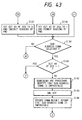
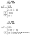
- a station which has received DCS can know whether the SUB and PWD signals have been transmitted, by checking bits 49 and 50 of the received DCS, respectively. Hence, an erroneous assumption as illustrated in Fig. 47B will not occur.
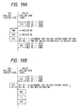
- Figs. 8A and 8B are sequence charts showing procedures of the present embodiment.
- Fig. 8A shows a procedure of the present embodiment when a called station has failed to receive the SUB and PWD signals.
- a called station determines that a calling station has sent the SUB and PWD signals, but the called station has failed to receive them.
- the called station After receiving a training (Tr) signal and a training check (TCF) signal, the called station sends a DIS signal again.
- Tr training
- TCF training check
- Fig. 8B shows a procedure of the present embodiment when the calling station has issued neither SUB signal nor PWD signal.
- the called station determines that the calling station has issued neither SUB signal nor PWD signal.
- the called station after receiving the training (Tr) signal and training check (TCF) signal, the called station sends a confirmation to receive for receiving (CFR) signal to the calling station and proceeds to image transmission.
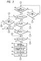
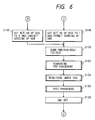
- FIGS. 2 to 6 are flowcharts showing operations of the control circuit 36 in the present embodiment.
- step S42 the control circuit 36 outputs a signal with signal level "0" to the signal line 36a to turn CML off.
- step S44 it generates a clear pulse in the signal line 36g to clear the received data storage designate lamp 32. In the present embodiment, when the lamp 32 is lit, sub-address communication is designated.
- step S46 the control circuit 36 takes in data outputted to the signal line 34a and determines whether the output of data stored in the memory circuit 26 is selected. It proceeds to step S48 if the output is selected and to step S50 if not.
- control circuit 36 outputs a signal with signal level "1" to the signal line 36d and outputs data stored in the memory circuit 26 through the signal line 36e. On completion of recording, it outputs a signal with signal level "0" to the signal line 36d.
- step S50 the control circuit 36 determines whether reception is selected. It proceeds to step S60 if reception is selected and to step S52 if not.
- step S52 the control circuit 36 determines whether transmission is selected. It proceeds to step S116 if transmission is selected and to step S54 to perform other process if not.
- step S60 the control circuit 36 outputs a signal with signal level "1" to the signal line 36a to turn CML on.
- step S62 it sets timer T1 to 35 seconds.
- step S64 the control circuit 36 sends an NSF/CSI/DIS signal.
- bits 47 selective polling receive function available
- 49 sub-address receive function available
- 50 password receive function available
- FIF Facsimile Information Field
- step S66 the control circuit 36 sets timer T4 to 4.5 seconds for manual reception and to 3 seconds for automatic reception. Then, in step S68, it determines whether a PWD/SUB/NSS/TSI/DCS signal is received. It proceeds to step S72 if received and to step S70 if not.
- step S70 the control circuit 36 determines whether a time out associated with timer T4 has occurred. It proceeds to step S74 if the time out has occurred and to step S68 if not.
- step S72 the control circuit 36 determines whether a DCS signal has been received. It proceeds to step S78 if the DCS signal is received and to step S74 if not.
- step S74 the control circuit 36 determines whether a time out associated with timer T1 has occurred. It proceeds to step S76 if the time out has occurred and to step S64 if not.
- step S76 the control circuit 36 outputs a signal with signal level "0" to the signal line 36a to turn CML off. Then, it returns to step S46.
- step S78 the control circuit 36 determines whether bit 49 or 50 of FIF of the DCS signal is 1. It proceeds to step S80 if YES and to step S98 if NO.
- step S80 the control circuit 36 determines whether bit 49 of FIF of the DCS signal is 1 and also bit 50 is 0, i.e. it checks for the combined state that sub-address reception is designated and that password reception is not designated. It proceeds to step S82 if YES and to step S92 if NO.
- bits 47, 49, and 50 of FIF of the DCS signal are all set to 0.
- bit 49 of FIF of the DCS signal when bit 49 of FIF of the DCS signal is 1, it indicates that the SUB signal is also sent in multiframe; when bit 49 is 0, it indicates that the SUB signal is not sent in multiframe.
- bit 50 of FIF of the DCS signal when bit 50 of FIF of the DCS signal is 1, it indicates that the PWD signal is also sent in multiframe; when bit 50 is 0, it indicates that the PWD is not sent in multiframe.
- bit 50 of FIF of the DCS signal when bit 50 of FIF of the DCS signal is 1, it indicates that the PWD signal is also sent in multiframe; when bit 50 is 0, it indicates that the PWD is not sent in multiframe.
- step S82 the control circuit 36 determines whether the SUB signal is received. When the SUB signal is received, it proceeds to step S84 and subsequent steps for reception in memory. When the SUB signal is not received, it determines that receiving the SUB signal has failed and returns to step S74.
- step S84 the control circuit 36 performs remaining pre-procedure.
- step S86 it stores received data in the memory circuit 26 through the signal line 36e.
- step S88 it performs post-procedure.
- step S90 it outputs a signal with signal level "0" to the signal line 36a to turn CML off and returns to step S46.
- step S92 the control circuit 36 determines whether bit 49 of FIF of the DCS signal is 0 and also bit 50 is 1, i.e. it checks for the combined state that sub-address reception is not designated and that password reception is designated. It proceeds to step S94 if YES and to step S112 if NO.
- step S94 the control circuit 36 determines whether the PWD signal is received. When the PWD signal is received, it proceeds to step S96. When the PWD signal is not received, it determines that receiving the PWD signal has failed and returns to step S74.
- step S96 the control circuit 36 determines whether the PWD signal and a password set in the receiving station accord. It proceeds to step S98 if they accord and to step S106 if not.
- step S98 the control circuit 36 performs remaining pre-procedure.
- step S100 it receives and records an image signal.
- step S102 it performs post-procedure.
- step S104 it outputs a signal with signal level "0" to the signal line 36a to turn CML off and returns to step S46.
- step S106 the control circuit 36 performs remaining pre-procedure. Here, it notifies that communication is terminated due to disaccord of passwords.
- step S108 it outputs a signal with signal level "0" to the signal line 36a to turn CML off.
- step S110 it records in a communication result report that communication has been terminated due to disaccord of passwords.
- step S112 the control circuit 36 determines whether the PWD signal is received. When the PWD signal is received, it proceeds to step S114. When the PWD signal is not received, it determined receiving the PWD signal has failed and returns to step S74.
- step S114 the control circuit 36 determines whether the PWD signal and a password set in the receiving station accord. It proceeds to step S82 if they accord and to step S106 if not.
- step S116 the control circuit 36 outputs a signal with signal level "1" to the signal line 36a to turn CML on.
- step S118 it sets timer T1 to 35 seconds.
- step S120 the control circuit 36 determines whether the NSF/CSI/DIS signal is received. It proceeds to step S126 if received and to step S122 if not.
- step S122 the control circuit 36 determines whether a time out associated with timer T1 has occurred. It proceeds to step S124 if the time out has occurred and returns to step S120 if not.
- step S124 the control circuit 36 outputs a signal with signal level "0" to the signal line 36a to turn CML off and returns to step S46.
- step S126 the control circuit 36 determines whether password communication is selected from a console unit, not shown. It proceeds to step S128 if selected and to step S137 if not.
- step S128 the control circuit 36 determines whether bit 50 of FIF of the DIS signal is 1, i.e. whether the password receive function is available. It proceeds to step S136 if YES and to step S130 if NO.
- step S130 the control circuit 36 performs remaining pre-procedure. Here, it notifies that password communication is impossible.
- step S132 it outputs a signal with signal level "0" to the signal line 36a to turn CML off.
- step S134 it records in the communication result report that password communication is impossible and returns to step S46.
- step S136 the control circuit 36 sets bit 50 of FIF of the DCS signal to 1 to notify the receiving station that the PWD signal is to be sent and permits the sending of the PWD signal.
- step S137 the control circuit 36 sets bit 50 of FIF of the DCS signal to 0 to notify the receiving station that the PWD signal is not to be sent and inhibits the sending of the PWD signal.
- step S138 the control circuit 36 determines whether sub-address communication is selected, i.e. specifically, whether the lamp 32 is lit. It proceeds to step S140 if YES and to step S149 if NO.
- step S140 the control circuit 36 determines whether bit 49 of FIF of the DIS signal is 1, i.e. whether the remote receiving station has the sub-address receive function. It proceeds to step S148 if YES and to step S142 if NO.
- step S142 the control circuit 36 performs remaining pre-procedure. Here, it notifies that sub-address communication is impossible.
- step S144 it outputs a signal with signal level "0" to the signal line 36a to turn CML off.
- step S146 it records in the communication result report that sub-address communication is impossible and returns to step S46.
- step S148 the control circuit 36 sets bit 49 of the DCS signal to 1 to notify the receiving station that the SUB signal is to be sent and permits the sending of the SUB signal.
- step S149 it sets bit 49 of the DCS signal to 0 to notify the receiving station that the SUB signal is not to be sent and inhibits the sending of the SUB signal.
- step S150 it sends the PWD/SUB/NSS/TSI/DCS signal according to steps S136, S137, S148, and S149.
- step S152 it performs remaining pre-procedure.
- step S154 it reads and sends an image signal.
- step S156 it performs post-procedure.
- step S158 it outputs a signal with signal level "0" to the signal line 36a to turn CML off and returns to step S46.
- the PWD and SUB signals are sent as receive command signals, and at this time, the sending of the signals is notified in FIF of the DCS signal.
- the PWD and SEP signals may be sent as a transmit command signal, and the sending of the signals may be notified in FIF of the DTC signal.
- the presence or absence of the PWD signal is assigned to bit 65 of FIF of the DTC signal
- the presence or absence of the SEP signal is assigned to bit 66 of FIF of the DTC signal.
- whether a non-standard facilities set-up (NSS) signal is included in a receive command signal may be notified to a remote station by a digital command signal (DCS), for example, bit 67 of FIF thereof.
- DCS digital command signal
- Fig. 7 is a flowchart showing a different part of control in this case from the first embodiment described above.
- step S162 determines whether bit 67 of FIF of the DCS signal is 1, i.e. whether the NSS signal is also sent. It proceeds to step S164 if YES and to step S78 described above if NO.
- step S164 the control circuit 36 determines whether the NSS signal is received. It proceeds to step S78 described above if received and to step S74 described above if not.
- step S172 it determines whether the NSF signal is received. It proceeds to step S174 if received and to step S126 described above if not.
- step S174 the control circuit 36 determines whether the NSS signal is to be sent. It proceeds to step S176 when the NSS signal is sent and to step S126 described above when the NSS signal is not sent.
- step S176 the control circuit 36 sets bit 67 of FIF of the DCS signal to 1 to designate the sending of the NSS signal to a remote receiving station and permits the sending of the NSS signal.
- whether a transmitting subscriber identification (TSI) signal is included in a receive command signal may be notified to a remote station by a digital command signal (DCS), for example, bit 68 of FIF thereof.
- DCS digital command signal
- an initial identification signal may be applied to the third and fourth embodiments described above, and whether a non-standard facilities (NSF) signal or a called station identification (CSI) signal is included may be notified to a remote station by a digital identification signal (DIS).
- NSF non-standard facilities
- CSI called station identification
- DIS digital identification signal
- the presence or absence of NSF is assigned to bit 67 of FIF of DIS
- the presence or absence of CSI is assigned to bit 68 of FIF of DIS.
- a transmit command signal may be applied to the third and fourth embodiments described above, and whether a non-standard facilities command (NSC) signal or a calling subscriber identification (CIG) signal is included may be notified to a remote station by a digital transmit command (DTC) signal.
- NSC non-standard facilities command
- CIG calling subscriber identification
- DTC digital transmit command
- the fact can be notified to a remote station by including it in FIF (facsimile information field) of the DCS signal, DIS signal, and DTC signal or the like.
- FIF facsimile information field
- the DCS signal, DIS signal, DTC signal and the like are sent in multiframe, respectively, and also when a receiving station side fails to receive part of the multiframe of these signals, it is possible for the receiving station side to properly recognize the failure. This prevents a difference in recognition between the sending and receiving station sides, leading to prevention of an erroneous operation.
- Figs. 9A and 9B are block diagrams showing a facsimile apparatus according to a fifth embodiment.
- Figs. 9A and 9B features functioning in the same manner as in Fig. 1 are denoted by common reference numerals, and description thereof is omitted.
- the memory circuit 38 stores the encoded data outputted to the signal line 12a under control of a signal line 36h and outputs the stored data to a signal line 38a.
- the circuit 40 decodes, variable-magnifies, and re-encodes the data, as needed, and outputs the processed data to a signal line 40a.
- the V27ter or V29 modulator 14 takes in the encoded data from the signal line 40a, modulates the encoded data according to the known ITU-T Recommendations V27ter (differential phase modulation) or V29 (quadrature modulation), and outputs the modulated data to the adder circuit 16 through the signal line 14a.
- a memory box number designate key 42 is used to designate a memory box number. After pressing the key 42, data is entered using a ten-key 43 to designate a memory box number. Specifically, the key 42 is used on a transmitting station side to designate a memory box in order to cause a remote receiving station side to store a received image therein (the memory box is notified to the remote receiving station by the SUB signal). Also, the key 42 is used on a polling receive side to designate a memory box on a remote polling send side data stored in which the polling receive side is to receive by polling (the memory box is notified to the remote polling send station by the SEP signal). When the designate key 42 is pressed, a press pulse is generated in a signal line 42a.
- the ten-key 43 is used to enter numerical data for dialing or the like. Data associated with a pressed ten-key is outputted to a signal line 43a.
- a memory polling select key 44 is used on the polling receive station side to designate the polling receive of data stored in a memory on the polling send station side.
- a press pulse is generated in a signal line 44a.
- a memory polling designate lamp 46 is used to designate memory polling receive.
- the lamp 46 goes off when a clear pulse is generated in a signal line 36i. Subsequently, the lamp 46 alternates between on and off each time a press pulse is generated in the signal line 44a.
- a signal with signal level "0" is outputted to a signal line 46a.
- a signal with signal level "1" is outputted to the signal line 46a.
- a password sending select key 48 is used to select the sending of a password signal in sending image data and at polling receive. When the key 48 is pressed, a press pulse is generated in a signal line 48a. A password is registered on the side of receiving the password signal. If the password signal sent from a password signal transmitting station side does not accord with the registered password, the receiving side rejects communication (reception).
- a password is registered on the polling send side. If a password signal sent from the polling receive station side does not accord with the registered password, the polling send side rejects communication (transmission).
- a sub-address is designated by the SUB signal, a memory box to store received image data is determined on the side of receiving the image data, and a memory box to be used for polling send is determined on the polling send side. If the SUB signal is not designated, a memory box with address 0 is to be selected.
- memory boxes ranging from address 0 to address 99 for example are available.
- a password sending designate lamp 50 is used to designate the sending of a password signal in sending image data and at polling receive.
- the lamp 50 goes off when a clear pulse is generated in a signal line 36j. Subsequently, the lamp 50 alternates between on and off each time a press pulse is generated in the signal line 48a.
- a signal with signal level "0" is outputted to a signal line 50a.
- a signal with signal level "1" is outputted to the signal line 50a.
- a password register circuit 52 is used to register a station password through a signal line 52a.
- a console unit 54 includes one-touch dialing keys, abbreviated dialing keys, a ten-key pad, a start key, password register keys, a set key, and other function keys. Data associated with a pressed key is outputted to a signal line 54a.
- a control circuit 36 performs operations similar to those of the first embodiment.
- the description of the fifth embodiment therefore, only covers what is not covered by the description of the first embodiment.
- the same control features as those of the first embodiment are denoted by common reference numerals, and description thereof is omitted.
- bit 50 of FIF of the DTC signal is set to 0.
- bit 47 of FIF of the DTC signal is set to 0.
- the fifth embodiment is identical to the first embodiment in definition of bits 47, 49, and 50 of DIS and DCS.
- bit 47 of DTC is assigned to indicate "whether the SEP signal has been sent”. This bit 47 is set to “1” when the SEP signal is sent and to "0" if not.
- Bit 49 of DTC is fixed to "0".
- bit 50 of DTC is assigned to indicate "whether the PWD signal has been sent”. This bit 50 is set to "1” when the PWD signal is sent and to "0" if not.
- the polling send station (called) can know whether the SEP and PWD signals have been transmitted, by checking bits 47 and 50 of a received DTC.
- Figs. 19A and 19B are sequence charts showing procedures of the present embodiment in polling communication.
- Fig. 19A shows a procedure of the present embodiment when a called station has failed to receive the SEP and PWD signals.
- a called station determines that a calling station has sent the SUB and PWD signals, but the called station has failed to receive them. Thus, the called station sends a DIS signal again.
- Fig. 19B shows a procedure of the present embodiment when the calling station has issued neither SEP signal nor PWD signal.
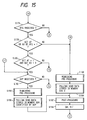
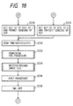
- Figs. 10 to 18 are flowcharts showing operations of the control circuit 36 in the fifth embodiment. The same steps as those of the first embodiment are denoted by common reference numerals, and description thereof is omitted.
- step S160 the control circuit 36 generates a clear pulse in the signal line 36i to turn the memory polling designate lamp 46 off.
- step S162 it generates a clear pulse in the signal line 36j to turn the password sending designate lamp 50 off.
- step S164 the control circuit 36 takes in data outputted to the signal line 54a and determines whether the registration of a station password is selected. It proceeds to step S166 if the registration is selected and to step S46 if not.
- step S46 the control circuit 36 takes in data outputted to the signal lines 34a, 42a, 43a, and 54a and determines whether the output of data stored in the memory circuit 26 is selected. It proceeds to step S48 if the output is selected and to step S50 if not.
- the control circuit 36 outputs a signal with signal level "1" to the signal line 36d and outputs data stored in the memory circuit 26 through the signal line 36e.
- a memory box is designated by the SUB signal, it outputs data stored in the designated memory box.
- a password is designated by the PWD signal, it outputs data after a password is entered. On completion of recording, it outputs a signal with signal level "0" to the signal line 36d.
- step S168 the control circuit 36 determines whether the storage of polling send data in a memory is selected. If the storage is selected, it proceeds to step S170 to store the polling send data in the memory circuit 38. Here, it is also possible for the control circuit 36 to take in data outputted to the signal lines 42a and 43a and to designate a memory box for storage. If the storage in the memory is not selected, it proceeds to step S172.
- step S172 the control circuit 36 determines whether polling receive is selected. It proceeds to step S206 (Fig. 17) if selected and to step S44 if not.
- step S174 of Fig. 11 the control circuit 36 determines whether the PWD/SEP/CIG/DTC signal is received. It proceeds to step S176 (Fig. 15) if received and to step S70 if not.
- step S176 of Fig. 15 the control circuit 36 determines whether the DTC signal is received. It proceeds to step S178 if received and to step S74 (Fig. 11) if not.
- step S178 the control circuit 36 determines whether bit 47 or 50 of FIF of the DTC signal is 1. It proceeds to step S180 if YES and to step S188 if NO.
- step S180 the control circuit 36 determines whether bit 47 of FIF of the DTC signal is 1 and also bit 50 thereof is 0, i.e. it checks for the combined state that a remote station designates the sending of the SEP signal in multiframe and that the remote station does not designate the sending of the PWD signal. It proceeds to step S182 if YES and to step S196 (Fig. 16) if NO.
- step S182 the control circuit 36 determines whether the SEP signal is received. When the SEP signal is received, it proceeds to step S184. When the SEP signal is not received, it determines that receiving the SEP signal has failed and returns to step S74 (Fig. 11).
- step S184 the control circuit 36 performs remaining pre-procedure.
- step S186 it performs a polling send of data stored in the memory circuit 38 through the signal line 36h. Here, it performs a polling send of data stored in a memory box which is designated by the SEP signal.
- step S188 the control circuit 36 performs remaining pre-procedure.
- step S190 it performs a polling send of data stored in the memory circuit 38 through the signal line 36h. Here, it performs a polling send of data stored in memory box 0.
- step S192 it performs post-procedure.
- step S194 it outputs a signal with signal level "0" to the signal line 36a to turn CML off and returns to step S44 (Fig. 10).
- step S196 the control circuit 36 determines whether bit 47 of FIF of the DTC signal is 0 and also bit 50 thereof is 1, i.e. it checks for the combined state that a remote station designates the sending of the PWD signal in multiframe and that the remote station does not designate the sending of the SEP signal. It proceeds to step S198 if YES and to step S202 if NO.
- step S198 the control circuit 36 determines whether the PWD signal is received. When the PWD signal is received, it proceeds to step S200. When the PWD signal is not received, it determines that receiving the PWD signal has failed and returns to step S74 (Fig. 11).
- step S200 the control circuit 36 determines whether the PWD signal and a password set in a station (registered in the circuit 52) accord. It proceeds to step S188 (Fig. 15) if they accord and to step S106 (Fig. 12) if not.
- step S202 the control circuit 36 determines whether the PWD signal is received. When the PWD signal is received, it proceeds to step S204. When the PWD signal is not received, it determines that receiving the PWD signal has failed and proceeds to step S74 (Fig. 11).
- step S204 the control circuit 36 determines whether the PWD signal and a password set in a station (registered in the circuit 52) accord. It proceeds to step S182 if they accord and to step S106 (Fig. 12) if not.
- Step S206 (Fig. 17) represents steps S116 and S118 of Fig. 13.
- the control circuit 36 turns CML on and sets timer T1 to 35 seconds.
- Step S208 represents step S120 of Fig. 13.
- the control circuit 36 proceeds to step S212. If not received, it proceeds to step S210.
- Step S210 represents step S122 of Fig. 13.
- the control circuit 36 proceeds to step S211 to turn CML off.
- no time out occurs, it proceeds to step S208.
- Step S212 represents step S126 of Fig. 13.
- the control circuit 36 takes in data on the circuit 50. It proceeds to step S214 when password communication is selected and to step S217 if not.
- Step S214 represents step S128 of Fig. 13.
- bit 50 of FIF of DIS is 1
- the control circuit 36 proceeds to step S216.
- bit 50 of FIF of DIS is 0, it proceeds to step S130 (Fig. 13).
- step S216 the control circuit 36 sets bit 50 of FIF of the DTC signal to 1 to notify a remote station that the PWD signal is to be sent and permits the sending of the PWD signal.
- step S217 the control circuit 36 sets bit 50 of FIF of the DTC signal to 0 to notify a remote (or partner) station that the PWD signal is not to be sent and inhibits the sending of the PWD signal.
- step S218 the control circuit 36 takes in data outputted to the signal lines 46a, 42a, and 43a. It determines whether a memory box for polling send is designated, i.e. specifically, it checks for the combined state that the lamp 46 is lit and that a memory box for polling send is designated. It proceeds to step S220 if YES and to step S229 (Fig. 18) if NO.
- step S220 the control circuit 36 determines whether bit 47 of FIF of the DIS signal is 1, i.e. whether a remote station has the selective polling send function (function of receiving the SEP signal). It proceeds to step S228 (Fig. 18) if YES and to step S222 if NO.
- step S222 the control circuit 36 performs remaining pre-procedure. Here, it notifies that selective polling communication is impossible.
- step S224 it outputs a signal with signal level "0" to the signal line 36a to turn CML off.
- step S2208 the control circuit 36 sets bit 47 of FIF of the DTC signal to 1 to notify a remote station that the SEP signal is to be sent and permits the sending of the SEP signal.
- step S229 the control circuit 36 sets bit 47 of FIF of the DTC signal to 0 to notify a remote station that the SEP signal is not to be sent and inhibits the sending of the SEP signal.
- step S230 it sends the PWD/SEP/CIG/DTC signal according to steps S216, S217, S228, and S229. Furthermore, in step S232, it performs remaining pre-procedure. In step S234, it polling-receives/records an image signal. Then, in step S236, it performs post-procedure. In step S238, it outputs a signal with signal level "0" to the signal line 36a to turn CML off and returns to step S44 (Fig. 10).
- the SEP and SUB signals may be used for the designation or the like of a terminal connected to LAN or the like.
- which optional signal is to be added can be made definite by declaration in the DTC signal. Furthermore, control when a DTC group signal is received can be made definite on the side which has sent an initial identification signal.
- the fifth embodiment has proposed a facsimile apparatus which sends again an initial identification signal when a receiving station side or polling send station side has received the notification of the presence of an optional signal, but has failed to receive a frame of the designated optional signal in such communication that the presence/absence of an optional signal is notified in a receive command signal or transmit command signal.
- a transmitting station side resends the PWD/SUB/NSS/TSI/DCS signal, or a polling receive station side resends the PWD/SEP/NSC/CIG/DTC signal. This causes a longer procedure time.
- the German Standard has involved the following drawback: in the case where after sending a DTC group signal, the polling receive side receives a DIS group signal without receiving a DCS group signal from the polling send side, it sends a DCN signal to terminate communication. That is, there has been a drawback that communication is disabled when facsimile in Japan is a polling send side and facsimile in Germany is a polling receive side.
- the present embodiment avoids a delay in communication procedure and disabled communication when a receiving station side or polling send station side has received the notification of the presence of an optional signal, but has failed to receive a frame of the designated optional signal in such communication that the presence/absence of an optional signal is notified in a receive command signal or transmit command signal.
- Fig. 20 is a block diagram showing a sixth embodiment of the present invention.
- a memory box number designate circuit 144 is used to designate a memory box number in order to specify a memory box for outputting stored data therefrom when the output of stored data is selected by the stored data output key 34.
- the designated memory box number is outputted to a signal line 144a.
- a memory polling box number designate circuit 146 is used to designate a memory box number for memory polling send when a memory polling receive is to be executed.
- the designated memory box number is outputted to the signal line 146a.
- a selective polling signal is used for notification from a memory polling receive station side to a memory polling send station side.
- An action setting circuit 152 is used to set a password signal for a local station.
- a password is set, at the time of sending and at memory polling receive, the password is sent.
- a password signal from a remote station, if received, is compared with the password set in the local station. If they accord, receiving and memory polling send will be executed.
- a password is not set, a password signal is not sent at the time of sending and at memory polling receive.
- the password signal is outputted to a signal line 152a.
- an action select circuit 150 is used to select any one of (A) re-sending an initial identification signal, (B) sending a CRP signal, and (C) waiting for a signal from a remote station, in the case where the local station has received a digital command signal or digital transmit command signal declaring the presence of an optional signal, but has failed to receive the declared optional signal.
- the selected data is outputted to a signal line 150a.
- the action setting circuit 152 is used to set an action ((1) re-sending an initial identification signal or (2) sending a CRP signal or (3) waiting for a signal from a remote station) to be selected according to a count of receiving a digital command signal or digital transmit command signal.
- the set data is outputted to a signal line 152a.
- control circuit 36 in the sixth embodiment exercises control according to an action selected from among (A) re-sending a DIS group signal, (B) sending a CRP signal, and (C) waiting for a receive command signal to be retransmitted, in the case where a local station has received a DCS signal declaring the inclusion of a sub-address signal or password signal, but has failed to receive the declared sub-address signal or password signal.
- Figs. 21 to 26 are flowcharts showing operations of the control circuit 36 in the present embodiment.
- step S50 the control circuit 36 determines whether reception or polling send is selected. It proceeds to step S60 if selected and to step S52 if not.
- step S52 the control circuit 36 determines whether transmission is selected. It proceeds to step S116 (Fig. 25) if selected and to step S172 if not.
- step S172 the control circuit 36 determines whether selective polling receive is selected. It proceeds to step S206 if selected and to step S54 if not.
- step S82 the control circuit 36 determines whether the SUB signal is received. When the SUB signal is received, it proceeds to step S84 and subsequent steps for reception in memory. When the SUB signal is not received, it determines that receiving the SUB signal has failed and proceeds to step S280 (Fig. 24).
- step S94 the control circuit 36 determines whether the PWD signal is received. When the PWD signal is received, it proceeds to step S96. When the PWD signal is not received, it determines that receiving the PWD signal has failed and proceeds to step S280 (Fig. 24).
- step S112 the control circuit 36 determines whether the PWD signal is received. When the PWD signal is received, it proceeds to step S114. When the PWD signal is not received, it determines that receiving the PWD signal has failed and proceeds to step S280 (Fig. 24).
- step S280 the control circuit 36 takes in data outputted to the signal line 150a to read data generated by the action select circuit 150.
- a local station has received a digital command signal declaring the presence of an optional signal, but has failed to receive the designated optional signal, it determines which action is selected, (A) re-sending an initial identification signal, (B) sending a CRP signal, or (C) waiting for a receive command signal to be retransmitted.
- re-sending an initial identification signal it proceeds to step S74 of Fig. 22.
- step S68 of Fig. 22 When waiting for a signal to be sent from a remote station is selected, it proceeds to step S68 of Fig. 22.
- sending a CRP signal is selected, it sends the CRP signal in step S282 and then proceeds to step S68 of Fig. 3.
- Figs. 27A, 27B and 27C show the manner of exchanging procedure signals including DCS.
- Fig. 27A shows case (A) of re-sending an initial identification signal.
- Fig. 27B shows case (B) of sending a CRP signal.
- Fig. 27C shows case (C) of waiting for a receive command signal to be retransmitted.
- a digital transmit command signal (DTC signal) is used to notify a remote station whether an optional signal is included in a transmit command signal.
- the polling send station side can select any one of (A) re-sending an initial identification signal, (B) sending a CRP signal, and (C) waiting for a transmit command signal to be retransmitted, in the case where the polling send station side has received a digital transmit command signal declaring the presence of an optional signal, but has failed to receive the declared optional signal.
- Figs. 28 to 33C illustrate only those control features of the sixth embodiment different from those of the fifth embodiment described above.
- the same control features are denoted by common reference numerals, and description thereof is omitted.
- step S182 the control circuit 36 determines whether the SEP signal is received. When the SEP signal is received, it proceeds to step S184 and subsequent steps to execute a memory polling send of data stored in a memory box designated by the SEP signal. When the SEP signal is not received, it determines that receiving the SEP signal has failed and proceeds to step S326 (Fig. 30).
- step S198 the control circuit 36 determines whether the PWD signal is received. When the PWD signal is received, it proceeds to step S200. When the PWD signal is not received, it determines that receiving the PWD signal has failed and proceeds to step S326 (Fig. 30).
- step S202 the control circuit 36 determines whether the PWD signal is received. When the PWD signal is received, it proceeds to step S204. When the PWD signal is not received, it determines that receiving the PWD signal has failed and proceeds to step S326 (Fig. 30).
- step S326 the control circuit 36 takes in data outputted to the signal line 150a to read data generated by the action select circuit 150.
- a local station has received a digital transmit command signal declaring the presence of an optional signal, but has failed to receive the designated optional signal, it determines which action is selected, (A) re-sending an initial identification signal, (B) sending a CRP signal, or (C) waiting for a receive command signal to be retransmitted.
- re-sending an initial identification signal it proceeds to step S74 of Fig. 22.
- step S68 of Fig. 22 When sending a CRP signal is selected, it sends the CRP signal in step S328 and then proceeds to step S68 (Fig. 22).
- Figs. 33A, 33B and 33C show the manner of exchanging procedure signals including DTC.
- Fig. 33A shows case (A) of re-sending an initial identification signal.
- Fig. 33B shows case (B) of sending a CRP signal.
- Fig. 33C shows case (C) of waiting for a transmit command signal to be retransmitted.
- the sixth embodiment provides control features to select therefrom for the case where the receiving station side has received a digital command signal or digital transmit command signal declaring the presence of an optional signal, but has failed to receive the declared optional signal.
- a communication time can be reduced, and an easy operation is implemented.
- whether a non-standard facilities set-up (NSS) signal is included in a receive command signal may be notified to a remote station by a digital command signal (DCS), for example, bit 67 of FIF thereof.
- DCS digital command signal
- Fig. 34 is a flowchart showing a different part of control in this case from the sixth embodiment described above.
- step S72 determines whether bit 67 of FIF of the DCS signal is 1, i.e. whether the NSS signal is also sent together with DCS. It proceeds to step S364 if YES and to step S78 (Fig. 22) if NO.
- step S364 the control circuit 36 determines whether the NSS signal is received. It proceeds to step S78 (Fig. 22) if received and to step S74 (Fig. 22) if not.
- step S120 Fig. 25
- step S372 Fig. 34
- step S372 determines whether the NSF signal is received. It proceeds to step S374 if received and to step S377 if not.
- step S374 the control circuit 36 determines whether the NSS signal is to be sent. It proceeds to step S376 when the NSS signal is sent and to step S377 when the NSS signal is not sent.
- step S176 the control circuit 36 sets bit 67 of FIF of the DCS signal to 1 to designate the sending of the NSS signal to a remote receiving station and permits the sending of the NSS signal.
- step S377 the control circuit 36 sets bit 67 of FIF of the DCS signal to 0 to designate not to send the NSS signal to a remote receiving station and inhibits the sending of the NSS signal.
- whether a transmitting subscriber identification (TSI) signal is included in a receive command signal may be notified to a remote station by a digital command signal (DCS), for example, bit 68 of FIF thereof.
- DCS digital command signal
- an initial identification signal may be applied to the seventh and eighth embodiments described above, and whether a non-standard facilities (NSF) signal or a called station identification (CSI) signal is included may be notified to a remote station by a digital identification signal (DIS).
- NSF non-standard facilities
- CSI called station identification
- DIS digital identification signal
- the presence or absence of NSF is assigned to bit 67 of FIF of DIS
- the presence or absence of CSI is assigned to bit 68 of FIF of DIS.
- a transmit command signal may be applied to the seventh and eighth embodiments described above, and whether a non-standard facilities command (NSC) signal or a calling subscriber identification (CIG) signal is included may be notified to a remote station by a digital transmit command (DTC) signal.
- NSC non-standard facilities command
- CIG calling subscriber identification
- DTC digital transmit command
- an action in response to the reception of the receive command signal or transmit command signal may be changed according to a count of reception.
- a local station when receiving an optional signal has failed in spite of the declaration of the presence of the optional signal, a local station waits for a receive command signal or transmit command signal to be retransmitted until they are received twice. However, in response to the third reception of them, the local station resends an initial identification signal. A series of actions for the three receptions is repeated.
- a line remains connected even when the local station does not respond to up to the second reception of a DTC signal sent from a remote station.
- the local station fails to properly receive an optional signal, it does not respond to up to the second reception of the DTC signal.
- it In response to the third reception of the DTC signal, it resends DIS. This reduces time required for two times of reception of the DTC signal. Since the DIS signal is sent in response to the third reception of the DTC signal, the line is disconnected, and hence no communication error occurs.
- Figs. 35 and 36 are flowcharts showing such part of control at reception of the DCS signal in the eleventh embodiment that is different from the sixth embodiment described above.
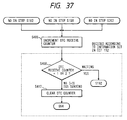
- Fig. 37 is a flowchart showing such part of control at reception of the DTC signal in the eleventh embodiment that is different from the sixth embodiment described above.
- actions corresponding to a count of reception of a DCS group or DTC group signal are set in the action setting circuit 152 as described below. That is, a signal from a remote station is waited for the first and second receptions, and DIS is sent for the third reception. These three actions are repeated.
- step S380 it sets a DCS receive counter indicative of a count of reception of DCS to 0.
- step S381 it sets a DTC receive counter indicative of a count of reception of DTC to 0. Then, it proceeds to step S60 and subsequent steps of Fig. 21.
- step S390 if NO in step S82 of Fig. 22, step S94 of Fig. 23, or step S112 of Fig. 23, the control circuit 36 proceeds to step S390.
- step S390 the control circuit 36 increments the DCS receive counter by 1 due to reception of DCS.
- the set data is such that a signal from a remote station is waited for when the content of the DCS receive counter is 1 or 2 and such that the DIS signal is retransmitted when the content of the DCS receive counter is 3.
- the set data is such that a signal from a remote station is waited for when the content of the DCS receive counter is 1 or 2 and such that the DIS signal is retransmitted when the content of the DCS receive counter is 3.
- the set data is such that a signal from a remote station is waited for when the content of the DCS receive counter is 1 or 2 and such that the DIS signal is retransmitted when the content of the DCS receive counter is 3.
- the set data is such that a signal from a remote station is waited for when the content of the DCS receive counter is 1
- step S406 if NO in step S182 of Fig. 28, step S198 of Fig. 29, or step S202 of Fig. 29, the control circuit 36 proceeds to step S406.
- step S406 the control circuit 36 increments the DTC receive counter by 1 due to reception of DTC. Then, it sets an action according to data set in the action setting circuit 152.
- the set data is such that a signal from a remote station is waited for when the content of the DTC receive counter is 1 or 2 and such that the DIS signal is retransmitted when the content of the DTC receive counter is 3.
- the control circuit 36 increments the DTC receive counter by 1 due to reception of DTC. Then, it sets an action according to data set in the action setting circuit 152.
- the set data is such that a signal from a remote station is waited for when the content of the DTC receive counter is 1 or 2 and such that the DIS signal is retransmitted when the content of the DTC receive counter is 3.
- a counter value of 1 or 2 it proceeds to step S68 of Fig. 22.
- a counter value of 3 it clears the DTC receive counter (step S412) and then proceeds to step S64 of Fig. 21.
- the transmitting station may suffer an error after the third attempt to send.
- the receiving station side when the receiving station side has received a digital command signal or digital transmit command signal declaring the presence of an optional signal, but has failed to receive the designated optional signal, the receiving station side does not answer first two receptions, thereby reducing communication time, and answers the third reception, thereby preventing the above mentioned error.
- the first embodiment has proposed notifying a remote station by a digital command signal (DCS signal) of whether an optional signal is included in a receive command signal for example.
- DCS signal digital command signal
- a facsimile apparatus having the function of the first embodiment is to receive data from a facsimile apparatus not having the facilities (hereinafter called a function of notifying the presence or absence of an optional signal; a facsimile apparatus having the function is called a new type facsimile apparatus, and a facsimile apparatus not having the function is called an old type facsimile apparatus), 0 is outputted both for the presence or absence of the sending of a sub-address signal included in the DCS signal (bit 49) and for the presence or absence of the sending of a password signal (bit 50).
- the new type facsimile apparats determines that both signals are not sent and thus fails to receive them even when the remote station (old type facsimile apparatus) sends the PWD signal or SUB signal.
- the ten-key 43 is used, for example, to designate a memory box for storage on the receiving station side from the transmitting station side or to designate a memory box number containing received data for outputting the data. Data associated with pressed keys on the ten-key pad is outputted to the signal line 43a.
- a set key 45 is used, for example, to indicate the end of data entry from the ten-key 43. Pressing the set key 45 causes pulses to be generated in a signal line 45a.
- the password setting circuit 52 is used to set a password.
- the password setting circuit 52 takes in data outputted to the signal line 52a to recognize a set password.
- a password if set, is sent as the PWD signal.
- communication continues only when the received PWD signal accords with a set password.
- the control circuit 36 controls a facsimile apparatus capable of notifying a remote station of whether an optional signal is included in a receive command signal, by declaration in a digital command signal (DCS signal).
- apparatus assumed as a send side by the present embodiment include a conventional facsimile apparatus which is unable to notify a remote station of whether an optional signal is included in a receive command signal, by declaration in a digital command signal (DCS signal).
- DCS signal digital command signal
- an apparatus of the present embodiment serves as a receive side.
- reception from either of the above mentioned two facsimile apparatus at reception from a facsimile apparatus capable of notifying a remote station of whether an optional signal is included in a receive command signal, by declaration in a digital command signal (DCS signal), (A) when the receive side has failed to receive an optional signal in spite of the presence of the optional signal being declared by the digital command signal (DCS signal), the receive side resends an initial identification signal; on the contrary, (B) when the receive side has received an optional signal in spite of the inclusion of the optional signal in a receive command signal being not declared by the digital command signal (DCS signal), the receive side handles the received optional signal as a valid one.
- DCS signal digital command signal
- an optional signal in a receive command signal is not declared by the digital command signal (DCS signal) in the following two cases: (1) a reception from a facsimile apparatus capable of notifying a remote station of whether an optional signal is included in a receive command signal, by declaration in a digital command signal (DCS signal), wherein not sending an optional signal is designated; (2) a reception from a facsimile apparatus which is unable to notify a remote station of whether an optional signal is included in a receive command signal, by declaration in a digital command signal (DCS signal).
- Optional signals considered are a password signal (PWD signal) and a sub-address signal (SUB signal).
- Figs. 39 to 45 are flowcharts showing operations of the control circuit 36 in the present embodiment.
- the same steps of the present embodiment as those of the first embodiment are denoted by common reference numerals, and description thereof is omitted.
- bits 47, 49, and 50 of FIF of the DCS signal are all set to 0.
- a facsimile apparatus employing this sending method is called an old type facsimile apparatus.
- bit 49 of FIF of the DCS signal when bit 49 of FIF of the DCS signal is 1, it indicates that the SUB signal is also sent in multiframe; when bit 49 is 0, it indicates that the SUB signal is not sent in multiframe.
- bit 50 of FIF of the DCS signal when bit 50 of FIF of the DCS signal is 1, it indicates that the PWD signal is also sent in multiframe; when bit 50 is 0, it indicates that the PWD is not sent in multiframe.
- a facsimile apparatus which follows this rule for sending is called a new type facsimile apparatus (first embodiment of the present application).
- step S96 the control circuit 36 determines whether the PWD and a password set in the receiving station, i.e. in the password setting circuit 52 accord. It proceeds to step S98 if they accord and to step S106 if not.
- step S114 the control circuit 36 determines whether the PWD and a password set in the receiving station, i.e. in the password setting circuit 52 accord. It proceeds to step S82 if they accord and to step S106 if not.
- step S126 the control circuit 36 determines whether a password is set in the password setting circuit 52, i.e. whether password communication is selected. It proceeds to step S128 if selected and to step S137 if not.
- step S128 the control circuit 36 determines whether bit 50 of FIF of the DIS signal is 1, i.e. whether the password receive function is available. It proceeds to step S129 if YES and to step S130 if NO.
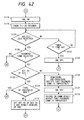
- step S129 the control circuit 36 determines whether the transmitting station is a new type facsimile apparatus. It proceeds to step S131 if the transmitting station is an old type facsimile apparatus and to step S136 if the transmitting station is a new type facsimile apparatus. In step S131, it sets bit 50 of FIF of the DCS signal to 0 (constant) and permits the sending of a password set in the password setting circuit 52, as the PWD signal. It proceeds to step S138 from step S131.
- step S136 the control circuit 36 sets bit 50 of FIF of the DCS signal to 1 in order to notify the receiving station of the sending of the PWD signal and permits the sending of a password set in the password setting circuit 52 as the PWD signal.
- step S140 the control circuit 36 determines whether bit 49 of FIF of the DIS signal is 1, i.e. whether the remote receiving station has the sub-address receive function. It proceeds to step S147 if YES and to step S142 if NO.
- step S147 the control circuit 36 determines whether the transmitting station is a new type facsimile apparatus. It proceeds to step S151 if the transmitting station is an old type facsimile apparatus and to step S148 if the transmitting station is a new type facsimile apparatus. In step S151, it sets bit 50 of FIF of the DCS signal to 0 (constant) and permits the sending of an entered memory box number as the SUB signal (step S149).
- step S148 the control circuit 36 sets bit 49 of the DCS signal to 1 in order to notify the receiving station of the sending of the SUB signal and permits the sending of an entered memory box number as the SUB signal. Then, in step S150, it sends the PWD/SUB/NSS/TSI/DCS signal according to steps S137, S131, S136, S149, S148, and S151.
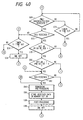
- the control circuit 36 proceeds to step S560 (Fig. 45) in the case of reception from an old type facsimile apparatus, wherein bits 49 and 50 of FIF of the DCS signal are both 0, or in the case of reception from a new type facsimile apparatus with the PWD and SUB signals not transmitted.
- this process routine applies to the case where neither PWD signal nor SUB signal is sent.
- the process routine becomes effective where reception from an old type facsimile apparatus is also involved, i.e. where both old and new types of facsimile apparatus are marketed.
- step S560 the control circuit 36 determines whether the PWD signal is received.
- the PWD signal proceeds to step S562 and determines whether the received PWD signal and a password set in the receiving station, i.e. in the password setting circuit 52 accord. If they accord, it proceeds to step S564. If not, it proceeds to S106 (Fig. 41).
- the PWD signal is not received, it proceeds to step S564 and determines whether the SUB signal is received. If received, it proceeds to step S84 (Fig. 40). If not, it proceeds to step S98 (Fig. 41).
- the PWD and SUB signals are set as a receive command signal, and at this time the sending thereof is declared in FIF of the DCS signal for notification.
- the PWD and SEP signals may be sent as a transmit command signal, and at this time the sending thereof may be declared in FIF of the DTC signal for notification.
- the presence or absence of the PWD signal is assigned to bit 50 of FIF of the DTC signal
- the presence or absence of the SEP signal is assigned to bit 47 of FIF of the DTC signal.
- a polling send side fails to receive the PWD signal in spite of bit 50 of FIF of the DTC signal being 1 or where the polling send side fails to receive the SEP signal in spite of bit 47 of FIF of the DTC signal being 1, the polling send side re-sends an initial identification signal. Furthermore, when the PWD signal or SEP signal is received in spite of bits 47 and 50 of FIF of the DTC signal being both 0, these received signals are considered valid in executing control.
- Figs. 46A to 46C show the manner of exchanging procedure signals of the twelfth embodiment.
- An apparatus of the twelfth embodiment is on the called side.
- the twelfth embodiment is different in operation from the first embodiment only as illustrated by Fig. 46C.
- the twelfth embodiment is effective to perform a precise process at reception from either of a facsimile apparatus which declares the presence or absence of an optional signal by a digital command signal (DCS signal) and a facsimile apparatus which does not.
- DCS signal digital command signal
- a facsimile apparatus which can make definite the presence or absence of optional signals such as a password signal (PWD), a sub-address signal (SUB), a selective polling signal (SEP) and the like in communication between transmitting and receiving stations, thereby preventing an erroneous operation.
- PWD password signal
- SEP selective polling signal
- a digital transmit command signal is used to notify a remote station whether a transmit command signal includes the password signal (PWD) and selective polling signal (SEP).
- a digital command signal is used to notify a remote station whether a receive command signal includes the password signal (PWD) and sub-address signal (SUB).
Landscapes
- Engineering & Computer Science (AREA)
- Computer Networks & Wireless Communication (AREA)
- General Engineering & Computer Science (AREA)
- Multimedia (AREA)
- Signal Processing (AREA)
- Facsimile Transmission Control (AREA)
Claims (20)
- Appareil de communication ayant une première fonction de procédure pour communiquer une pluralité de signaux de procédure normaux (DIS, DCS) et une seconde fonction de procédure pour communiquer une pluralité de signaux de procédure optionnels (PWD, SUB), ledit appareil comportant :un moyen de réception destiné à recevoir, depuis une destination, un premier signal de procédure normal (DIS) indiquant que la destination possède la seconde fonction de procédure (bit 49, 50) ; etun moyen de transmission qui, en réponse au premier signal de procédure normal (DIS), est destiné à transmettre, à la destination, un second signal de procédure normal (DCS) comprenant une information (bit 49, 50) indiquant une communication des signaux de procédure facultatifs (PWD, SUB), et un premier signal de procédure facultatif (PWB, SUB) pour la seconde fonction de procédure.
- Procédé de communication pour un appareil de communication ayant une première fonction de procédure pour communiquer une pluralité de signaux de procédure normaux (DIS, DCS) et une seconde fonction de procédure pour communiquer une pluralité de signaux de procédure facultatifs (PWD, SUB), ledit procédé comprenant les étapes consistant :à recevoir, depuis une destination, un premier signal de procédure normal (DIS) indiquant que la destination possède la seconde fonction de procédure (bit 49, 50) ; età transmettre, en réponse au premier signal de procédure normal (DIS), un second signal de procédure normal (DCS) comprenant une information indiquant une communication des signaux de procédure facultatifs (PWD, SUB) et un premier signal de procédure facultatif (PWD, SUB) pour la seconde fonction de procédure à la destination.
- Appareil de communication ayant une première fonction de procédure pour communiquer une pluralité de signaux de procédure normaux (DIS, DCS) et une seconde fonction de procédure pour communiquer une pluralité de signaux de procédure facultatifs (PWD, SUB), ledit appareil comportant :un moyen de transmission destiné à transmettre, à une destination, un premier signal de procédure normal (DIS) indiquant que ledit appareil possède la seconde fonction de procédure (bit 49, 50)un moyen de réception destiné à recevoir le second signal de procédure normal (DCS) ou un premier signal de procédure facultatif (PWD, SUB) et le second signal de procédure normal (DCS), en tant que signal de réponse correspondant au premier signal de procédure normal (DIS) provenant de la destination ; etun moyen de détermination destiné à distinguer si une information (bit 49, 50) indiquant une communication des signaux de procédure facultatifs (PWD, SUB) a été établie ou non dans le second signal de procédure normal reçu (DCS), et à déterminer, dans le cas où le premier signal de procédure facultatif (PWD, SUB) n'a pas été reçu de la destination, une erreur de réception du premier signal de procédure facultatif (PWD, SUB) conformément à une distinction de l'information (bit 49, 50) dans le second signal de procédure normal (DCS).
- Procédé de communication pour un appareil de communication ayant une première fonction de procédure pour communiquer une pluralité de signaux de procédure normaux (DIS, DCS) et une seconde fonction de procédure pour communiquer une pluralité de signaux de procédure facultatifs (PWD, SUB), ledit procédé comprenant les étapes qui consistent :à transmettre, à une destination, un premier signal de procédure normal (DIS) indiquant que ledit appareil possède la seconde fonction de procédure ;à recevoir un second signal de procédure normal (DCS) ou un premier signal de procédure facultatif (PWD, SUB) et le second signal de procédure normal (DCS), en tant que signal de réponse correspondant au premier signal de procédure normal (DIS) provenant de la destination ;à distinguer si une information (bit 49, 50) indiquant une communication des signaux de procédure facultatifs (PWD, SUB) a été établie ou non dans le second signal de procédure normal reçu (DCS), età déterminer, dans un cas où le premier signal de procédure facultatif (PWD, SUB) n'a pas été reçu de la destination, une erreur de réception du premier signal de procédure facultatif (PWD, SUB) conformément à la distinction de l'information (bit 59, 50) dans le second signal de procédure normal (DCS).
- Appareil selon la revendication 3 ou procédé selon la revendication 4, dans lequel, dans un cas où le premier signal de procédure facultatif (PWD, SUB) n'a pas été reçu et l'information (bit 49, 50) a été établie dans le second signal de procédure normal reçu (DCS), ledit moyen/ladite étape de détermination déterminent l'erreur de réception du premier signal de procédure facultatif (PWD, SUB).
- Appareil ou procédé selon la revendication 5, comprenant en outre, dans le cas d'un appareil, un moyen destiné à amener ledit moyen de réception à recevoir le premier signal de procédure facultatif (PWD, SUB) retransmis depuis la destination lorsque ledit moyen de détermination détermine l'erreur de réception du premier signal de procédure facultatif (PWD, SUB), ou bien, dans le cas d'un procédé, une étape de réception du premier signal de procédure facultatif (PWD, SUB) retransmis depuis la destination lorsque ladite étape de détermination détermine l'erreur de réception du premier signal de procédure facultatif (PWD, SUB).
- Appareil selon la revendication 3 ou procédé selon la revendication 4, dans lequel, dans un cas où le premier signal de procédure facultatif (PWD, SUB) n'a pas été reçu et l'information (bit 49, 50) n'a pas été établie dans le second signal de procédure normal reçu (DCS), ledit moyen/ladite étape de détermination déterminent que la destination ne possède pas la seconde fonction de procédure.
- Appareil selon la revendication 3 ou procédé selon la revendication 4, comprenant en outre, dans le cas d'un appareil, un moyen de sélection ou bien, dans le cas d'un procédé, une étape de sélection pour sélectionner, conformément au résultat de la détermination dudit moyen/de ladite étape de détermination, l'une quelconque des étapes suivantes :(A) une retransmission du premier signal de procédure normal (DIS) ;(B) la transmission d'un troisième signal de procédure normal (CRP) indiquant que le premier signal de procédure facultatif (DIS) n'est pas reçu convenablement ; et(C) une non-transmission d'un signal de procédure à la destination, mais le fait d'amener ledit moyen/ladite étape de réception à recevoir le premier signal de procédure facultatif (PWD, SUB) retransmis depuis la destination.
- Appareil ou procédé selon la revendication 8, dans lequel ledit moyen/ladite étape de sélection sélectionnent parmi (A), (B) et (C) conformément à un comptage d'erreur déterminé par ledit moyen/ladite étape de détermination.
- Appareil ou procédé selon la revendication 9, dans lequel ledit moyen/ladite étape de sélection sélectionnent (B) ou (C) pour jusqu'à une seconde erreur déterminée par ledit moyen/ladite étape de détermination et sélectionnent (A) pour une troisième erreur.
- Procédé de communication entre des premier et second appareils de communication selon la revendication 3, ledit second appareil de communication étant la destination, le procédé comprenant les étapes qui consistent :à transmettre, depuis ledit premier appareil de communication audit second appareil de communication, le premier signal de procédure normal (DIS) ;à transmettre, depuis ledit second appareil de communication audit premier appareil de communication, en réponse au premier signal de procédure normal (DIS), le second signal de procédure normal (DCS) et le premier signal de procédure facultatif (PWD, SUB) pour la seconde fonction de procédure ;à recevoir, dans ledit premier appareil de communication, au moins le second signal de procédure normal (DCS) en tant que signal de réponse correspondant au premier signal de procédure normal (DIS) ; età distinguer, dans ledit premier appareil de communication, si l'information (bit 49, 50) indiquant de communiquer les signaux de procédure facultatifs (PWD, SUB) a été établie ou non dans le second signal de procédure normal reçu (DCS), et à déterminer, dans le cas où le premier signal de procédure facultatif (PWD, SUB) n'a pas été reçu du second appareil de communication, une erreur de réception du premier signal de procédure facultatif (PWD, SUB) conformément à la distinction de l'information (bit 49, 50) dans le second signal de procédure normal (DCS).
- Appareil selon la revendication 1 ou procédé selon la revendication 2 ou 11, dans lequel ledit moyen/ladite étape de transmission transmettent le premier signal de procédure facultatif (PWD, SUB) et le second signal de procédure normal (DCS) sous la forme d'une série de signaux.
- Appareil selon la revendication 1 ou 3 ou procédé selon la revendication 2, 4 ou 11, dans lequel les signaux de procédure normaux (DIS, DCS) et les signaux de procédure facultatifs (PWD, SUB) sont des signaux de procédure de télécopie définis dans une recommandation ITU-T.
- Appareil ou procédé selon la revendication 13, dans lequel le premier signal de procédure normal est un signal d'identification numérique défini dans la recommandation ITU-T T.30 et le second signal de procédure normal est un signal d'ordre de transmission numérique défini dans la recommandation ITU-T T.30.
- Appareil ou procédé selon la revendication 14, dans lequel le premier signal de procédure facultatif est un signal d'identification d'abonnés transmettant défini dans une recommandation ITU-T.
- Appareil ou procédé selon la revendication 14, dans lequel le premier signal de procédure facultatif est un signal d'ordre d'installation non normal défini dans une recommandation ITU-T.
- Appareil ou procédé selon la revendication 14, dans lequel le premier signal de procédure facultatif est un signal d'identification d'abonnés appelant défini dans un recommandation ITU-T.
- Appareil ou procédé selon la revendication 14, dans lequel le premier signal de procédure facultatif est un signal de mots de passe défini dans une recommandation ITU-T.
- Appareil ou procédé selon la revendication 14, dans lequel le premier signal de procédure facultatif est un signal d'appel sélectif défini dans une recommandation ITU-T.
- Appareil ou procédé selon la revendication 14, dans lequel le premier signal de procédure facultatif est un signal de sous-adresse défini dans une recommandation ITU-T.
Applications Claiming Priority (12)
| Application Number | Priority Date | Filing Date | Title |
|---|---|---|---|
| JP78025/94 | 1994-03-24 | ||
| JP7802594 | 1994-03-24 | ||
| JP07802594A JP3554015B2 (ja) | 1994-03-24 | 1994-03-24 | ファクシミリ装置 |
| JP12312794 | 1994-05-12 | ||
| JP123127/94 | 1994-05-12 | ||
| JP12312794A JP3535568B2 (ja) | 1994-05-12 | 1994-05-12 | ファクシミリ装置 |
| JP6162754A JPH089087A (ja) | 1994-06-21 | 1994-06-21 | ファクシミリ装置 |
| JP16275494 | 1994-06-21 | ||
| JP16275394A JP3412917B2 (ja) | 1994-06-21 | 1994-06-21 | ファクシミリ装置 |
| JP162753/94 | 1994-06-21 | ||
| JP162754/94 | 1994-06-21 | ||
| JP16275394 | 1994-06-21 |
Publications (3)
| Publication Number | Publication Date |
|---|---|
| EP0674424A2 EP0674424A2 (fr) | 1995-09-27 |
| EP0674424A3 EP0674424A3 (fr) | 1996-03-13 |
| EP0674424B1 true EP0674424B1 (fr) | 2001-11-07 |
Family
ID=27466128
Family Applications (1)
| Application Number | Title | Priority Date | Filing Date |
|---|---|---|---|
| EP95104300A Expired - Lifetime EP0674424B1 (fr) | 1994-03-24 | 1995-03-23 | Dispositif de communication |
Country Status (5)
| Country | Link |
|---|---|
| US (2) | US5671270A (fr) |
| EP (1) | EP0674424B1 (fr) |
| CN (1) | CN1119026C (fr) |
| DE (1) | DE69523653T2 (fr) |
| ES (1) | ES2162876T3 (fr) |
Families Citing this family (15)
| Publication number | Priority date | Publication date | Assignee | Title |
|---|---|---|---|---|
| EP0674424B1 (fr) * | 1994-03-24 | 2001-11-07 | Canon Kabushiki Kaisha | Dispositif de communication |
| DE19645257C2 (de) * | 1996-11-02 | 2000-08-31 | Deutsche Telekom Ag | Verfahren zur Subadressierung von Fax-Dokumenten |
| US6038037A (en) * | 1996-12-13 | 2000-03-14 | Qualcomm Incorporated | Digital network interface for analog fax equipment |
| JPH10243206A (ja) | 1997-02-24 | 1998-09-11 | Canon Inc | 通信装置 |
| US6281987B1 (en) * | 1997-03-12 | 2001-08-28 | Canon Kabushiki Kaisha | Communication apparatus |
| JPH10322534A (ja) * | 1997-05-21 | 1998-12-04 | Murata Mach Ltd | ファクシミリ装置、ファクシミリ制御方法及びファクシミリ制御プログラムを記録した記録媒体 |
| JP3610199B2 (ja) | 1997-09-10 | 2005-01-12 | キヤノン株式会社 | データ通信システム |
| JP3485451B2 (ja) * | 1997-09-10 | 2004-01-13 | シャープ株式会社 | 通信装置 |
| JP3630961B2 (ja) * | 1997-12-05 | 2005-03-23 | キヤノン株式会社 | 通信装置 |
| JP3599562B2 (ja) | 1998-04-22 | 2004-12-08 | キヤノン株式会社 | 通信装置およびその制御方法 |
| JP3593257B2 (ja) * | 1998-05-13 | 2004-11-24 | 株式会社リコー | ファクシミリ装置 |
| JP2000151830A (ja) | 1998-11-06 | 2000-05-30 | Canon Inc | データ通信装置 |
| JP2000151945A (ja) | 1998-11-06 | 2000-05-30 | Canon Inc | データ通信装置 |
| US6379383B1 (en) | 1999-11-19 | 2002-04-30 | Advanced Bio Prosthetic Surfaces, Ltd. | Endoluminal device exhibiting improved endothelialization and method of manufacture thereof |
| US20030184783A1 (en) * | 2002-03-28 | 2003-10-02 | Toshiba Tec Kabushiki Kaisha | Modular layer for abstracting peripheral hardware characteristics |
Family Cites Families (15)
| Publication number | Priority date | Publication date | Assignee | Title |
|---|---|---|---|---|
| JPH0620228B2 (ja) * | 1984-03-13 | 1994-03-16 | キヤノン株式会社 | フアクシミリ装置 |
| JPS60218974A (ja) * | 1984-04-16 | 1985-11-01 | Canon Inc | フアクシミリ装置 |
| GB2170075B (en) * | 1984-12-28 | 1989-08-23 | Canon Kk | Image communication apparatus |
| US4885755A (en) * | 1985-04-10 | 1989-12-05 | Canon Kabushiki Kaisha | Method and apparatus for data communication |
| JPS6265554A (ja) * | 1985-09-17 | 1987-03-24 | Toshiba Corp | フアクシミリの通信方法 |
| US5093857A (en) * | 1986-10-17 | 1992-03-03 | Canon Kabushiki Kaisha | Communication apparatus for selected data and speech communication |
| US5128985A (en) * | 1987-04-01 | 1992-07-07 | Canon Kabushiki Kaisha | Communication system having a plurality of voice communication terminals and a data communication terminal |
| KR910002218A (ko) * | 1989-06-30 | 1991-01-31 | 정용문 | 팩시밀리 비표준기능 수행시의 재다이얼 제어방법 |
| FR2665595B1 (fr) * | 1990-08-03 | 1992-11-13 | Sagem | Procede de communication de telecopie. |
| JP2803764B2 (ja) * | 1990-10-15 | 1998-09-24 | キヤノン株式会社 | フアクシミリ装置 |
| EP0487308B1 (fr) * | 1990-11-21 | 2000-01-26 | Canon Kabushiki Kaisha | Communication d'images au couleurs |
| JPH0548781A (ja) * | 1991-08-14 | 1993-02-26 | Canon Inc | フアクシミリ装置 |
| JP2546113B2 (ja) * | 1992-12-17 | 1996-10-23 | 村田機械株式会社 | ファクシミリ装置 |
| US5521719A (en) * | 1993-03-22 | 1996-05-28 | Ricoh Company, Ltd. | Communication apparatus having improved group 3 facsimile subaddress communication function |
| EP0674424B1 (fr) * | 1994-03-24 | 2001-11-07 | Canon Kabushiki Kaisha | Dispositif de communication |
-
1995
- 1995-03-23 EP EP95104300A patent/EP0674424B1/fr not_active Expired - Lifetime
- 1995-03-23 US US08/409,053 patent/US5671270A/en not_active Expired - Lifetime
- 1995-03-23 DE DE69523653T patent/DE69523653T2/de not_active Expired - Lifetime
- 1995-03-23 ES ES95104300T patent/ES2162876T3/es not_active Expired - Lifetime
- 1995-03-24 CN CN95104092A patent/CN1119026C/zh not_active Expired - Lifetime
-
1997
- 1997-06-30 US US08/885,661 patent/US6072597A/en not_active Expired - Lifetime
Also Published As
| Publication number | Publication date |
|---|---|
| EP0674424A3 (fr) | 1996-03-13 |
| DE69523653T2 (de) | 2002-08-01 |
| CN1119026C (zh) | 2003-08-20 |
| US5671270A (en) | 1997-09-23 |
| EP0674424A2 (fr) | 1995-09-27 |
| DE69523653D1 (de) | 2001-12-13 |
| ES2162876T3 (es) | 2002-01-16 |
| CN1115151A (zh) | 1996-01-17 |
| US6072597A (en) | 2000-06-06 |
Similar Documents
| Publication | Publication Date | Title |
|---|---|---|
| US5721731A (en) | Data communication apparatus | |
| EP0674424B1 (fr) | Dispositif de communication | |
| JP2871704B2 (ja) | 画像通信方法 | |
| US5726765A (en) | Data communication apparatus for setting the baud rate and bit rate of a modem and performing data communication at the set baud rate and bit rate | |
| US5438427A (en) | Facsimile apparatus with controlled image page transmission after retransmission | |
| US5943364A (en) | Data communication apparatus for setting bit rate according to line quality | |
| US5748334A (en) | Facsimile apparatus capable of performing a standard procedure and a non-standard procedure | |
| JP2617468B2 (ja) | 画像通信装置 | |
| US5561533A (en) | Data communication apparatus having a multi-address transmission function | |
| KR0170469B1 (ko) | 통신 장치 | |
| JP3531881B2 (ja) | ファクシミリ装置 | |
| JP3535568B2 (ja) | ファクシミリ装置 | |
| JP2754012B2 (ja) | ファクシミリ通信方法 | |
| JP2556344B2 (ja) | ファクシミリ装置 | |
| JP3554015B2 (ja) | ファクシミリ装置 | |
| US5311579A (en) | Image communication apparatus with instructed communication result transmittal | |
| JPH0681236B2 (ja) | ファクシミリ通信方法 | |
| JP2584749B2 (ja) | 通信装置 | |
| JP2590102B2 (ja) | 画像送信装置 | |
| JP3197805B2 (ja) | データ通信装置 | |
| JP3192446B2 (ja) | ファクシミリ装置及び画像データの通信方法 | |
| JP2003101799A (ja) | 画像通信装置、画像通信方法および画像通信装置の制御方法 | |
| JPH0773325B2 (ja) | ファクシミリ通信方法 | |
| JP3157857B2 (ja) | ファクシミリ装置 | |
| JPH089087A (ja) | ファクシミリ装置 |
Legal Events
| Date | Code | Title | Description |
|---|---|---|---|
| PUAI | Public reference made under article 153(3) epc to a published international application that has entered the european phase |
Free format text: ORIGINAL CODE: 0009012 |
|
| AK | Designated contracting states |
Kind code of ref document: A2 Designated state(s): DE ES FR GB IT |
|
| PUAL | Search report despatched |
Free format text: ORIGINAL CODE: 0009013 |
|
| AK | Designated contracting states |
Kind code of ref document: A3 Designated state(s): DE ES FR GB IT |
|
| 17P | Request for examination filed |
Effective date: 19960731 |
|
| 17Q | First examination report despatched |
Effective date: 19980827 |
|
| GRAG | Despatch of communication of intention to grant |
Free format text: ORIGINAL CODE: EPIDOS AGRA |
|
| GRAG | Despatch of communication of intention to grant |
Free format text: ORIGINAL CODE: EPIDOS AGRA |
|
| GRAG | Despatch of communication of intention to grant |
Free format text: ORIGINAL CODE: EPIDOS AGRA |
|
| GRAH | Despatch of communication of intention to grant a patent |
Free format text: ORIGINAL CODE: EPIDOS IGRA |
|
| GRAH | Despatch of communication of intention to grant a patent |
Free format text: ORIGINAL CODE: EPIDOS IGRA |
|
| GRAA | (expected) grant |
Free format text: ORIGINAL CODE: 0009210 |
|
| AK | Designated contracting states |
Kind code of ref document: B1 Designated state(s): DE ES FR GB IT |
|
| REF | Corresponds to: |
Ref document number: 69523653 Country of ref document: DE Date of ref document: 20011213 |
|
| REG | Reference to a national code |
Ref country code: GB Ref legal event code: IF02 |
|
| REG | Reference to a national code |
Ref country code: ES Ref legal event code: FG2A Ref document number: 2162876 Country of ref document: ES Kind code of ref document: T3 |
|
| PLBE | No opposition filed within time limit |
Free format text: ORIGINAL CODE: 0009261 |
|
| STAA | Information on the status of an ep patent application or granted ep patent |
Free format text: STATUS: NO OPPOSITION FILED WITHIN TIME LIMIT |
|
| 26N | No opposition filed | ||
| PGFP | Annual fee paid to national office [announced via postgrant information from national office to epo] |
Ref country code: DE Payment date: 20140331 Year of fee payment: 20 |
|
| PGFP | Annual fee paid to national office [announced via postgrant information from national office to epo] |
Ref country code: ES Payment date: 20140313 Year of fee payment: 20 Ref country code: IT Payment date: 20140304 Year of fee payment: 20 |
|
| PGFP | Annual fee paid to national office [announced via postgrant information from national office to epo] |
Ref country code: GB Payment date: 20140318 Year of fee payment: 20 |
|
| PGFP | Annual fee paid to national office [announced via postgrant information from national office to epo] |
Ref country code: FR Payment date: 20140326 Year of fee payment: 20 |
|
| REG | Reference to a national code |
Ref country code: DE Ref legal event code: R071 Ref document number: 69523653 Country of ref document: DE |
|
| REG | Reference to a national code |
Ref country code: GB Ref legal event code: PE20 Expiry date: 20150322 |
|
| PG25 | Lapsed in a contracting state [announced via postgrant information from national office to epo] |
Ref country code: GB Free format text: LAPSE BECAUSE OF EXPIRATION OF PROTECTION Effective date: 20150322 |
|
| REG | Reference to a national code |
Ref country code: ES Ref legal event code: FD2A Effective date: 20150529 |
|
| PG25 | Lapsed in a contracting state [announced via postgrant information from national office to epo] |
Ref country code: ES Free format text: LAPSE BECAUSE OF EXPIRATION OF PROTECTION Effective date: 20150324 |