EP0674867A1 - Verbesserungen an oder bei Kleiderbügeln - Google Patents
Verbesserungen an oder bei Kleiderbügeln Download PDFInfo
- Publication number
- EP0674867A1 EP0674867A1 EP95302194A EP95302194A EP0674867A1 EP 0674867 A1 EP0674867 A1 EP 0674867A1 EP 95302194 A EP95302194 A EP 95302194A EP 95302194 A EP95302194 A EP 95302194A EP 0674867 A1 EP0674867 A1 EP 0674867A1
- Authority
- EP
- European Patent Office
- Prior art keywords
- coat hanger
- hook portion
- hanger
- coat
- divergent
- Prior art date
- Legal status (The legal status is an assumption and is not a legal conclusion. Google has not performed a legal analysis and makes no representation as to the accuracy of the status listed.)
- Withdrawn
Links
- 230000000717 retained effect Effects 0.000 claims description 19
- 239000000463 material Substances 0.000 claims description 10
- 229920003023 plastic Polymers 0.000 claims description 8
- 239000004033 plastic Substances 0.000 claims description 8
- 238000005728 strengthening Methods 0.000 claims description 6
- 238000001746 injection moulding Methods 0.000 claims description 3
- 238000000034 method Methods 0.000 claims description 3
- 210000003811 finger Anatomy 0.000 description 4
- 210000003739 neck Anatomy 0.000 description 3
- 238000005452 bending Methods 0.000 description 2
- 230000014759 maintenance of location Effects 0.000 description 2
- 210000000707 wrist Anatomy 0.000 description 2
- 238000007792 addition Methods 0.000 description 1
- 230000000694 effects Effects 0.000 description 1
- 230000005484 gravity Effects 0.000 description 1
- 238000004519 manufacturing process Methods 0.000 description 1
- 239000002184 metal Substances 0.000 description 1
- 238000012986 modification Methods 0.000 description 1
- 230000004048 modification Effects 0.000 description 1
- 230000000135 prohibitive effect Effects 0.000 description 1
- 238000003860 storage Methods 0.000 description 1
- 210000003813 thumb Anatomy 0.000 description 1
Images

Classifications
-
- A—HUMAN NECESSITIES
- A47—FURNITURE; DOMESTIC ARTICLES OR APPLIANCES; COFFEE MILLS; SPICE MILLS; SUCTION CLEANERS IN GENERAL
- A47G—HOUSEHOLD OR TABLE EQUIPMENT
- A47G25/00—Household implements used in connection with wearing apparel; Dress, hat or umbrella holders
- A47G25/74—Necktie holders ; Belt holders
- A47G25/743—Necktie holders ; Belt holders of the clothes hanger-type
-
- A—HUMAN NECESSITIES
- A47—FURNITURE; DOMESTIC ARTICLES OR APPLIANCES; COFFEE MILLS; SPICE MILLS; SUCTION CLEANERS IN GENERAL
- A47G—HOUSEHOLD OR TABLE EQUIPMENT
- A47G25/00—Household implements used in connection with wearing apparel; Dress, hat or umbrella holders
- A47G25/14—Clothing hangers, e.g. suit hangers
- A47G25/28—Hangers characterised by their shape
-
- A—HUMAN NECESSITIES
- A47—FURNITURE; DOMESTIC ARTICLES OR APPLIANCES; COFFEE MILLS; SPICE MILLS; SUCTION CLEANERS IN GENERAL
- A47G—HOUSEHOLD OR TABLE EQUIPMENT
- A47G25/00—Household implements used in connection with wearing apparel; Dress, hat or umbrella holders
- A47G25/14—Clothing hangers, e.g. suit hangers
- A47G25/28—Hangers characterised by their shape
- A47G25/32—Hangers characterised by their shape involving details of the hook
Definitions
- This invention relates to improvements in or relating to coat hangers.
- this invention relates to improvements in or relating to coat hangers which may be utilised for supporting and/or retaining more than one garment.
- hanger or "coat hanger” are used generically to describe any type of hanger for hanging any type of garment.
- coat hangers One of the simplest forms of coat hangers presently available is in the form of a continuous length of wire bent appropriately to form a coat hanger with a hook portion, a pair of divergent runs extending from the hook portion, and a cross bar extending between the pair of divergent runs.
- Such metal wire coat hangers are primarily adapted to support/retain shirts (or light pairs of trousers or skirts that do not bend the cross bar). They therefore have limitations in that they are not inherently adapted to support more than one garment, or garments other than shirts.
- the cost of having to supply different coat hangers for different garments may be of particular concern or relevance to drycleaners who are often required to dryclean more than one garment for a customer at one time.
- a drycleaner may be required to dryclean a pair of trousers and a tie for a customer at the same time. This creates problems when returning the garments, once drycleaned, since they have to be returned on separate hangers (one hanger for the trousers and one hanger for the tie), which has cost disadvantages associated therewith.
- the drycleaner must attach the tie to the coat hanger supporting the trousers (for example by the use of safety pins, clips, or by tying the tie to the hanger), which may be fiddly, costly, and/or time consuming.
- the customer may inadvertently damage the tie when separating it from the coat hanger.
- French Patent No. 2.484.821 describes a coat hanger which incorporates a resilient clip, at the base of the yoke of the hanger, for retaining a tie or belt.
- a disadvantage associated with the use of this hanger is that the teeth of the clip tend to bite into the tie/belt which may scuff same.
- the coat hanger is designed only to support/retain a garment such as a shirt with a garment such as a tie or belt, and there is therefore no provision for the hanger to also be able to support/retain garments such as skirts, dresses, shorts, and the like.
- the manufacturing methods associated with producing such a coat hanger/clip combination may be viewed as being overly complicated and/or costly.
- US Patent No. 4,714,183 describes a multi-purpose coat hanger which is provided with various brackets, bars and clips for retaining dresses, ties and skirts (as well as shirts and trousers) on one hanger.
- a disadvantage associated with the use of this hanger is that it is bulky and cumbersome, and perhaps overly complicated for a coat hanger.
- the hanger described in US Patent No. 4,714,183 requires a substantial amount of plastics material to form same (especially having regard to the number and size of the various brackets and bars which must be formed within the trapezoidal shape of the coat hanger).
- hanger Another disadvantage associated with the hanger is that there is no provision of releasable retention means or gripping means for the bar adapted for supporting a tie or for the brackets adapted for supporting straps of dresses. Hence, ties or dresses may therefore be inadvertently dislodged from the bars or brackets from time to time.
- coat hangers Another disadvantage associated with presently available coat hangers, such as those described above, is that the hook portions of the coat hangers (and/or the hangers themselves) are not specifically designed to accommodate the hand of a person carrying the coat hanger, and particularly when carrying more than one garment-laden coat hanger in one hand.
- drycleaners are often required to carry a number of coat hangers (laden with garments) in one hand, with the hand of the carrier usually being slid up and inside the mouth or opening of the hook portion of the hanger(s).
- All of the hook portions of the above prior art coat hangers usually end up digging into the hand of the carrier (or otherwise providing discomfort for the carrier), since the hook portions (and/or the hangers themselves) are not designed to specifically and comfortably accommodate the hand of a person carrying the hanger(s), and particularly when a large number of hangers.
- a coat hanger comprising:
- a coat hanger substantially as described above, wherein said at least one slot is adapted to support/retain a substantially elongate garment such as a tie or belt.
- a coat hanger substantially as described above, wherein the outer surface of the divergent run adjacent to the opening of the hook portion is curved to accommodate the hand of a person carrying the coat hanger.
- a coat hanger substantially as described above, wherein the curve of the outer surface of the divergent run adjacent to the opening of the hook portion is continuous and/or regular.
- a coat hanger substantially as described above, wherein the outer surface of the divergent run adjacent the back of the hook portion is curved, the curve being continuous and/or regular.
- a coat hanger substantially as described above, wherein the curve of the outer surface of the divergent run adjacent the back of the hook portion is steeper than the curve of the outer surface of the divergent run adjacent to the opening of the hook portion.
- a coat hanger substantially as described above, wherein the hook portion describes a semi-circle.
- the at least one slot formed in or through the yoke portion of the coat hanger may preferably be adapted for receiving and supporting/retaining a substantially thin and/or elongate garment such as a tie, belt, or scarf.
- the slot may be particularly suitable for receiving and supporting/retaining a tie.
- the at least one slot may preferably be substantially elongate and preferably between 3 to 10mm in width.
- the at least one slot may be of any suitable or required length depending upon the size of the coat hanger or the type of garment to be received and supported/retained thereby. It is envisaged however that a preferable length will be in the range of 5 to 10 cm.
- the coat hanger may be particularly suitable for use by a drycleaner, since (and for example only) the coat hanger may support a pair of trousers over the cross bar of the coat hanger, and a tie through or by the slot formed in the yoke portion of the coat hanger.
- a drycleaner need not have to otherwise attach the tie to the coat hanger supporting the pair of trousers.
- slots may be formed within the yoke portion, although in a preferred embodiment only one or two slots may be formed within the yoke portion of the coat hanger.
- the outer surface of the divergent run adjacent to the opening of the hook portion may be curved in an appropriate fashion to accommodate (and preferably comfortably accommodate) the hand of a person carrying the coat hanger.
- the curve of the outer surface of the divergent run adjacent to the opening of the hook portion may be continuous and/or regular.
- regular is defined as meaning that the curve of the outer surface of the divergent run is smooth and/or is not provided with any straight or non-curved portions.
- the hook design of the coat hanger (or the coat hanger itself) to be adapted or designed to readily and comfortably accommodate the hand of a carrier and particularly when carrying many coat hangers which may be laden with many garments (and therefore be of significant weight). Namely, it is preferable that no part of the hook portion or yoke portion of a coat hanger be allowed to dig into the hand of a carrier.
- a (preferably continuous and/or regular) curved portion in or along the outer surface of the divergent run adjacent to the opening of the hook portion together with the provision of divergent runs which extend downwardly and away from the curved portion allows for the hand of a person carrying the coat hanger to be readily and comfortably accommodated by the opening of the hook portion when carrying the coat hanger.
- the present design of the hook portion may render the coat hanger particularly suitable for use by drycleaners who are often required to carry many coat hangers in one hand (usually heavily laden with garments). That is, the hook design of the coat hanger allows for many coat hangers, laden with garments, to be carried comfortably and without any significant discomfort to the hand of the person carrying the coat hangers.
- Such a design compares favourably with many presently available coat hangers, wherein the outer surface of the divergcnt run adjacent to the opening of the hook portion of such prior art hangers is not curved, or comprises a straight portion and a curved portion.
- the hook (or hanger) designs of such prior art hangers are not specifically adapted or designed to (comfortably) accommodate the hand of a person carrying the hanger, and often result in the hook portion of the coat hanger digging into the hand of a person carrying same.
- the outer surface of the divergent run adjacent to the opening of the hook portion may be provided with appropriately formed depressions and/or ridges which may be specifically designed or contoured so as to fit the hand, palm or the fingers of the hand of a person carrying the coat hanger.
- the outer surface of the divergent run adjacent the back of the hook portion may also be curved, the curve also preferably being continuous and/or regular.
- the curve of the outer surface of the divergent run adjacent the back of the hook portion may be steeper than the curve of the outer surface of the divergent run adjacent to the opening of the hook portion (when the coat hanger is viewed upright and with the cross bar substantially horizontal).
- Such an arrangement allows for or provides for the opening of the hook portion to be adapted or specifically designed to readily and comfortably accommodate the hand of a person carrying the coat hanger, as described above.
- the yoke portion may therefore be asymmetrical in shape, due to the outer surface of the divergent run adjacent the back of the hook portion being steeper than the curve of the outer surface of the divergent run adjacent to the opening of the hook portion.
- the shape and configuration of the yoke portion may be such that a lesser area of the yoke portion may lie in the region adjacent the opening of the hook portion, as compared to the region adjacent the back of the hook portion, when an axis is drawn perpendicular to the cross bar, and halfway therealong. It is found that such a asymmetrical yoke design provides the coat hanger with substantial stability when hung from a bar or other means. Furthermore, the asymmetrical yoke design allows or provides for the coat hanger to be self-balancing or self-correcting if the weight of a garment supported by the coat hanger is not evenly distributed over the hanger.
- the hook portion may preferably describe a semi-circle, and preferably a substantially regular semi-circle.
- a semi-circle and preferably a substantially regular semi-circle.
- Such a design compares to presently available coat hangers which have hook portions which describe a shape other than a regular semi-circle (for example, a curved portion and a straight portion), or alternatively a circular shape which is greater or more rounded than a semi-circle (for example a three quarters circle).
- An advantage of a substantially regular semi-circular hook design is that the hook portion (and in particular the distal end of the hook portion) does not dig into the hand of a person carrying the coat hanger (or numerous hangers), as compared to prior art coat hangers.
- the area of the yoke portion may be significant or substantial, and particularly when compared to other presently available coat hangers.
- the width of the yoke portion (at its widest point) may preferably be significant or substantial, and in particular when compared to other presently available coat hangers.
- the area of the yoke portion may preferably be in the region of 30 to 70 square centimetres. An area of approximately 50 square centimetres may be particularly appropriate.
- the width of the yoke portion at its widest point may preferably be in the region of 8 to 20 centimetres, with 12 to 14 centimetres being particularly suitable.
- One advantage associated with having a yoke portion of such substantial width and/or area is that it allows for less movement or deformation of the hook portion (or yoke portion) about or with respect to the yoke portion or the divergent runs extending from the base of the hook portion or the yoke portion. That is, having a yoke portion of substantial area and/or width provides it with significant rigidity, and/or renders the hook portion (or yoke portion) less susceptible to deformation, bending, or twisting (or breaking).
- an asymmetrical yoke design also provides the yoke portion with significant rigidity, and/or allows for less deformation or twisting of the hook portion (or yoke portion) as compared to other presently available coat hangers (which generally have substantially symmetrical yoke portions or alternatively no significant yoke portion at all).
- Another advantage associated with having a yoke portion of substantial area and/or width is that it leaves a space for advertising within the yoke portion. This may be of advantage to a coat hanger manufacturer or to a drycleaner both or whom may advertise within the area of the yoke portion. Alternatively, and for example, a drycleaner may charge for other companies to advertise within the yoke portion of the coat hangers, thus providing another source of revenue.
- An advantage associated with having a yoke portion of substantial width is that shirts tend to hang better with a wider yoke portion, as compared to narrow yoke portions. Namely, coat hangers with thin or narrow yoke portions or necks cause shirts hanging from the coat hanger to close up, bunch up, or crumple.
- the significant width of the yoke portion of the present coat hanger allows for or causes shirts hung therefrom to sit evenly on or about the coat hanger, and to slightly open up which prevents the shirts from crumpling or creasing, as well as presenting the shirts in a more aesthetically pleasing manner. Again, and for example, this is of advantage to a drycleaner since shirts may be better presented (that is, with the necks slightly open) when being returned to customers.
- the coat hanger may preferably be provided with at least one gripping means for releasably retaining a garment(s) supported by the cross bar. Any suitable gripping means may be utilised as required or as desired, or as dictated by the type of garment to be supported by the cross bar.
- the gripping means may be in the form of a resilient downward sloping arm extending, for example, from at least one of the pair of divergent runs.
- a garment to be hung over and supported by the cross bar (for example a pair of trousers) may therefore be releasably retained by the downward sloping arm. That is, the downward sloping arm may serve to releasably clamp or hold the trousers to or about the cross bar.
- the distance between the end of the downward sloping arm and the cross bar may be minimal, and preferably in the range of 0 to 2mm, with 1mm being preferable.
- Trousers that are thicker than 2mm when hung over or supported by the cross bar may still be retained by the downward sloping arm given its resilient nature. That is, the arm may be bent upwards to allow the trousers to be hung over and supported by the cross bar and then released to provide downward pressure on the trousers and thereby retain the trousers on or about the cross bar. If the gap were to be larger than 2mm, most trousers may not be adequately retained on or about the cross bar by the resilient arm (unless the trousers are made of a particularly thick or bulky material).
- the gripping means such as in the form of a downward sloping arm, as described above, only places minimal pressure upon a garment such as a pair of trousers, and hence the gripping means does not, in any way, scuff or mark the garment due to any significant holding pressure.
- the gripping means such as a resilient downward sloping arm, may be provided in the region or regions where the inner surfaces of the pair of divergent arms meet the cross bar.
- the pair of divergent runs may also be provided with strap support means for receiving and supporting/retaining the straps of a garment such as a dress. Any suitable strap support means may be utilised as required or as desired or as dictated by the types of garments, such as dresses, to be supported.
- the strap support means may be in the form of open ended slots formed in each of the divergent runs, with the straps of a dress to be supported being able to be received and retained by the open ended slots.
- the open ended slots may be formed in each of the divergent runs at substantially identical points along their length.
- the coat hanger may also be provided with other or additional garment support means in the regions where the outer surfaces of the pair of divergent runs meet the cross bar.
- additional garment support means may be utilised for supporting any other type of garments, for example the waist band (or loops) of skirts or shorts.
- Such additional garment support means may preferably be in the form of hook shaped portions.
- the cross bar may preferably be provided with at least one strengthening rib, and the at least one strengthening rib may preferably extend along the length of the cross bar, and preferably the entire length of the cross bar.
- the cross bar may be provided with two such strengthening ribs on each side thereof.
- the slot(s) formed in the yoke portion may be provided with gripping means for releasably retaining a garment(s) supported by the slot, for example a tie.
- the gripping means may be of any suitable form, as required or as desired, or as dictated by the type of garment to be supported/retained by the slot(s).
- the gripping means may be in the form of a resilient downward sloping arm extending from an upper and/or side portion or surface of the slot.
- the garment such as a tie may therefore be releasably retained within or by the slot by virtue of pressure from the downward sloping arm retaining the garment to or about the lower surface of the slot.
- the downward sloping arm may extend to within 0 to 2mm of the lower surface of the slot, and preferably approximately 1mm.
- the coat hanger may be comprised of any suitable materials as required or as desired or as otherwise considered appropriate.
- the coat hanger may be formed of a plastics material, and preferably re-grind plastics material.
- the coat hanger and the features associated with same, may preferably be integrally formed.
- the coat hanger may preferably be formed from injection moulding techniques (which are well known and need not be described in detail herein).
- coat hanger of the present invention may be utilised to support more than one garment.
- the coat hanger may be utilised to support a shirt, a tie (through the slot formed in the yoke portion), a dress (supported by the strap support means), and a skirt or pair of shorts (supported by the additional garment support means described above).
- coat hanger being able to support more than one garment is that the storage of various garments within a closet may take up less room, as less coat hangers will be required.
- the coat hanger being of relatively simple design, may be manufactured quickly, cost-effectively, and with only a minimal amount of (plastics) material being required (and particularly when compared to the coat hanger described in US Patent No. 4,714,183).
- coat hanger advantages include the area/width and/or assymetrical shape of the yoke portion, and the design of the opening of the hook portion which allows for it to readily and comfortably accommodate the hand of a person carrying the coat hanger.
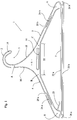
- the coat hanger 1 comprises a hook portion, generally indicated by arrow 2, the hook portion 2 having an opening 3 therefor.
- the hanger 1 further comprises a pair of divergent runs 4,5 extending downwardly and away from a yoke portion 6, the yoke portion 6 being situated at or towards the base A of the hook portion 2.
- the yoke portion 6 is provided with a substantially elongate slot 10 formed therethrough.
- the slot 10 is specifically adapted or designed to receive and support/retain a tie.
- the opening of the slot 10 is 7cm in length, and 6mm in width.
- the outer surface 11 of the divergent run 5 adjacent to the opening 3 of the hook portion 2 is curved in an appropriate fashion to accommodate the hand 12 (see Figure 2) of a person carrying the coat hanger 1.
- the palm 13 of the hand 12 lies or rests along the curved portion 11.
- the distal end 14 of the hook portion 2 lies along or adjacent to the back 15 of the hand 12.
- the distal end 14 of the hook portion 2 rests on or in the fleshy portion of the hand 12 between the thumb 29 and the index finger (not shown).
- the fingers of the hand 12 are pointing into the page of Figure 2, as viewed, with the wrist of the hand 12 protruding out of the page - fingers and wrist not shown).
- the curved portion 11 is continuous (in the region of the yoke portion 6) and regular, and it may be appreciated from Figure 2 that the curved portion 11 allows for the palm 13 of the hand 12 of the carrier to be readily, easily and comfortably accommodated when carrying the hanger 1 as shown in Figure 2. Moreover, the provision of the downward sloping divergent run 5 allows for the hand 12 of a carrier to be readily slid up and along/into the run 5, and along the curved portion 11 and into the opening 3 of the hook portion 2 (as shown).
- the hook design of the present invention ensures that the distal end 14 of the hook portion 2 does not dig into the back 15 of the hand 12 of a person carrying the coat hanger 1.
- the dotted outline 21 shows how the hook portion 21 may dig into the back 15 of the hand 12 of a person carrying the hanger 1 if the hook portion 21 were to describe a three quarter circle (as illustrated by the dotted outline 21), as compared to the hook portion 2 which describes a substantially regular semi-circle.
- This feature may be of importance or advantage to drycleaners who are often required to carry many coat hangers (laden with garments) in one hand (in the manner illustrated in Figure 2). That is, if the hook portion 2 were to dig into the back 15 of the hand 12 of the carrier, it may create substantial discomfort.
- the design of the hook portion 2, as described above, will also comfortably and readily accommodate the hand 12 of a carrier if the back 15 of the hand 12 were to lie or rest on the curved portion 11 (as compared to the palm 13).
- the outer surface 16 of the divergent run 4 adjacent the back 17 of the hook portion 2 is also curved, the curve also being continuous and regular.
- the curved portion 16 is however much steeper than the curved portion 11 (when the coat hanger 1 is viewed as illustrated in Figures 1 and 2).
- the gentler slope of the curved portion 11 allows for the curved portion 11 to readily accommodate the hand 12 of a carrier, as described previously.
- the yoke portion 6 is therefore asymmetrical in shape as illustrated.
- the asymmetrical design of the yoke portion 6 is such that a lesser area of the yoke portion 6 lies in the region 18 adjacent the opening 3 of the hook portion 2, as compared to the region 19 adjacent the back 17 of the hook portion 2 when an axis 20 is drawn perpendicular to the cross bar 7, and halfway therealong.
- the asymmetrical design of the yoke portion 6 provides the coat hanger with significant stability when hung from a bar or other means. Furthermore, the asymmetrical design of the yoke portion 6 allows or provides for the coat hanger to be self-balancing or self-correcting if the weight of a garment supported by the coat hanger 1 is not evenly distributed over or along the hanger 1.
- the area of the yoke portion 6 is substantial, and particularly when compared to other presently available coat hangers. Moreover, the width of the yoke portion 6 (at its widest point) is also substantial, and particularly when compared to other presently available coat hangers.
- the yoke portion 6 (which extends approximately from point A to point B to point C in a roughly asymmetrical triangular configuration) is approximately 50 square centimetres. Furthermore, the yoke portion 6, at its widest point 22, is approximately 13cm in width.
- the coat hanger 1 is provided with gripping means for releasably retaining a garment supported by the cross bar 7.
- the gripping means is in the form of a resilient downward sloping arm 23 which extends from the divergent run 4 (in the region where the inner surface of the divergent run 4 meets the cross bar 7).
- the distance between the arm 23 and the cross bar 27 (at the closest point) is approximately one millimetre.
- the coat hanger 1 is also provided with strap support means for receiving and supporting/retaining the strap of a garment such as a dress.
- the strap support means are in the form of open ended slots 24a,b.
- the open ended slots 24a,b are formed in each of the divergent runs 4,5, and at identical points along their length.
- the straps of a dress may slide down the divergent runs 4,5 and into the open ended slots 24a,b to therefore be supported/retained thereby. It may also be appreciated from Figure 1 that the design of the open ended slots 24a,b allow for the straps of the dress to be securely retained thereby, whereby they may not inadvertently be dislodged from the open ended slots 24a,b if the coat hanger 1 were to be bumped, for example. That is, the force of gravity will readily retain the straps of the dress within the slots 24a,b. The straps of the dress may however be readily removed from the open ended slots 24a,b by lifting the straps upward and out of the openings 25a,b of the slots 24a,b.
- the coat hanger 1 is also provided with additional garment support means in the regions where the outer surfaces of the pair of divergent runs 4,5 meet the cross bar 7.
- the additional garment support means are in the form of hook shaped portions 26a,b.
- the hook shaped portions 26a,b are specifically designed to receive and retain (and therefore support) any other type of garments, for example the waistband (or loops) of skirts or shorts.
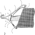
- Figure 3 illustrates a perspective view of the coat hanger 1 when being utilised to support/retain both a tie 27 and a pair of trousers 28.
- the tie 27 is fed through and supported/retained by the slot 10.
- the coat hanger 1 differs slightly from the embodiments shown in Figures 1 and 2, since the slot 10 incorporates releasable retention means, or gripping means, in the form of a resilient downward sloping arm 30.
- the arm 30 extends from one end 31 of the slot 10, and the arm 30 extends to within lmm of the lower surface 32 of the slot 10.
- the tie 27 may therefore be releasably retained within the slot 10 by virtue of (gentle) pressure from the arm 30.
- the pair of trousers 28 are supported and retained by the cross bar 7 by being draped thereover. Furthermore, the trousers 28 are releasably retained on or about the cross bar 7 by the downward sloping arm 23. That is, the arm 23 may be bent upwards to allow the trousers 28 to be hung over and supported by the cross bar 7, and then released to provide (gentle) downward pressure on the trousers 28 and thereby retain the trousers 28 on or about the cross bar 7.
- the cross bar 7 is provided with two strengthening ribs 33a,b.
- the ribs 33a,b extend virtually the entire length of the cross bar 7.
- the coat hanger 1 illustrated in Figures 1, 2, and 3 is integrally formed of re-grind plastics material. Furthermore, the coat hanger 1 is formed from injection moulding techniques.
- the coat hanger 1 may be particularly suitable for use by drycleaners who may return more than one garment to a customer at one time.
- a drycleaner may return a shirt, a tie, a pair of trousers, a dress, and a skirt (or a pair of shorts) to a customer on one coat hanger.
Landscapes
- Holders For Apparel And Elements Relating To Apparel (AREA)
Applications Claiming Priority (2)
| Application Number | Priority Date | Filing Date | Title |
|---|---|---|---|
| NZ26023094 | 1994-03-31 | ||
| NZ26023094A NZ260230A (en) | 1994-03-31 | 1994-03-31 | Coat hanger with yoke portion having at least one slot therethrough for tie or belt |
Publications (1)
| Publication Number | Publication Date |
|---|---|
| EP0674867A1 true EP0674867A1 (de) | 1995-10-04 |
Family
ID=19924738
Family Applications (1)
| Application Number | Title | Priority Date | Filing Date |
|---|---|---|---|
| EP95302194A Withdrawn EP0674867A1 (de) | 1994-03-31 | 1995-03-31 | Verbesserungen an oder bei Kleiderbügeln |
Country Status (4)
| Country | Link |
|---|---|
| EP (1) | EP0674867A1 (de) |
| AU (1) | AU1622695A (de) |
| CA (1) | CA2146054A1 (de) |
| NZ (1) | NZ260230A (de) |
Cited By (4)
| Publication number | Priority date | Publication date | Assignee | Title |
|---|---|---|---|---|
| GB2359988A (en) * | 2000-03-06 | 2001-09-12 | Hangers On Ltd | Garment hanger |
| WO2003003884A1 (en) * | 2001-07-04 | 2003-01-16 | Ultimate Apparel Pty Ltd | Garment hanger and system of transporting garments |
| EP1459660A1 (de) * | 2003-03-17 | 2004-09-22 | The Zebra Company | Kunststoff-Kleiderbügel mit erhöhter Steifigkeit |
| GB2486254A (en) * | 2010-12-09 | 2012-06-13 | Braitrim Uk Ltd | Garment hanging apparatus with deformable tab fixings |
Families Citing this family (1)
| Publication number | Priority date | Publication date | Assignee | Title |
|---|---|---|---|---|
| WO1999007263A2 (en) * | 1997-08-04 | 1999-02-18 | Rosebay Terrace Pty. Ltd. | A garment hanger system |
Citations (6)
| Publication number | Priority date | Publication date | Assignee | Title |
|---|---|---|---|---|
| US2123518A (en) * | 1935-11-23 | 1938-07-12 | Bozhidar M Yankovitch | Garment hanger |
| US2492226A (en) * | 1947-01-25 | 1949-12-27 | Para Lux Products Company | Necktie rack |
| FR1214092A (fr) * | 1959-01-23 | 1960-04-06 | Porte-vêtements perfectionné | |
| US4168791A (en) * | 1978-03-24 | 1979-09-25 | Tantera, Inc. | Folding hanger |
| DE9015054U1 (de) * | 1989-11-17 | 1991-01-17 | Triumph International AG, 8000 München | Kleiderbügel für die verkaufsgerechte Präsentation von Miederwaren, Unterwäsche, Badebekleidung o.dgl. |
| DE9317947U1 (de) * | 1993-11-24 | 1994-01-27 | Werinius, Per I., Lerum | Kleiderbügel |
-
1994
- 1994-03-31 NZ NZ26023094A patent/NZ260230A/en unknown
-
1995
- 1995-03-31 CA CA 2146054 patent/CA2146054A1/en not_active Abandoned
- 1995-03-31 AU AU16226/95A patent/AU1622695A/en not_active Abandoned
- 1995-03-31 EP EP95302194A patent/EP0674867A1/de not_active Withdrawn
Patent Citations (6)
| Publication number | Priority date | Publication date | Assignee | Title |
|---|---|---|---|---|
| US2123518A (en) * | 1935-11-23 | 1938-07-12 | Bozhidar M Yankovitch | Garment hanger |
| US2492226A (en) * | 1947-01-25 | 1949-12-27 | Para Lux Products Company | Necktie rack |
| FR1214092A (fr) * | 1959-01-23 | 1960-04-06 | Porte-vêtements perfectionné | |
| US4168791A (en) * | 1978-03-24 | 1979-09-25 | Tantera, Inc. | Folding hanger |
| DE9015054U1 (de) * | 1989-11-17 | 1991-01-17 | Triumph International AG, 8000 München | Kleiderbügel für die verkaufsgerechte Präsentation von Miederwaren, Unterwäsche, Badebekleidung o.dgl. |
| DE9317947U1 (de) * | 1993-11-24 | 1994-01-27 | Werinius, Per I., Lerum | Kleiderbügel |
Cited By (6)
| Publication number | Priority date | Publication date | Assignee | Title |
|---|---|---|---|---|
| GB2359988A (en) * | 2000-03-06 | 2001-09-12 | Hangers On Ltd | Garment hanger |
| WO2003003884A1 (en) * | 2001-07-04 | 2003-01-16 | Ultimate Apparel Pty Ltd | Garment hanger and system of transporting garments |
| EP1459660A1 (de) * | 2003-03-17 | 2004-09-22 | The Zebra Company | Kunststoff-Kleiderbügel mit erhöhter Steifigkeit |
| FR2852504A1 (fr) * | 2003-03-17 | 2004-09-24 | Zebra Compagny | Cintre pour vetement en matiere plastique a rigidite renforcee |
| GB2486254A (en) * | 2010-12-09 | 2012-06-13 | Braitrim Uk Ltd | Garment hanging apparatus with deformable tab fixings |
| GB2486254B (en) * | 2010-12-09 | 2013-01-16 | Braitrim Uk Ltd | Garment hanging apparatus |
Also Published As
| Publication number | Publication date |
|---|---|
| AU1622695A (en) | 1995-10-12 |
| NZ260230A (en) | 1996-01-26 |
| CA2146054A1 (en) | 1995-10-01 |
Similar Documents
| Publication | Publication Date | Title |
|---|---|---|
| US6609640B1 (en) | Pinch-grip hanger | |
| US5361949A (en) | Pants hanger with pivotable finger on lower bar | |
| US5129557A (en) | Garment hanger for thin garments held in clips with two channels | |
| US4991894A (en) | Carrying handle | |
| US4759480A (en) | Garment hanger with auxiliary bar | |
| US7377409B1 (en) | Victorian eagle organizer | |
| EP0656185A2 (de) | Verstellbarer Kleiderbügel | |
| US6915931B2 (en) | Garment set hanger | |
| US3194458A (en) | Garment hangers | |
| US4856688A (en) | Hanger carrying/holding device | |
| US4109838A (en) | Garment hanger | |
| GB2198340A (en) | Sliding clamp garment hanger | |
| US5950884A (en) | Suspender hanging assembly | |
| NZ260230A (en) | Coat hanger with yoke portion having at least one slot therethrough for tie or belt | |
| US6062232A (en) | Hair accessory holder for upright attachment | |
| JP2005021564A (ja) | ハンガー | |
| US3934317A (en) | Means for detachable support of keys within a pocket of an article of clothing | |
| US20100301075A1 (en) | Clothes hanger | |
| US20060011670A1 (en) | Three-piece swimwear hanger | |
| US3414176A (en) | Garment hanger | |
| US2812889A (en) | Clothes hanger with added retaining means | |
| US3779053A (en) | Means for detachable support of keys within a pocket of an article of clothing | |
| US3237820A (en) | Garment hanger | |
| US20050017031A1 (en) | Garment hanger | |
| JPH11509755A (ja) | 衣服ハンガー |
Legal Events
| Date | Code | Title | Description |
|---|---|---|---|
| PUAI | Public reference made under article 153(3) epc to a published international application that has entered the european phase |
Free format text: ORIGINAL CODE: 0009012 |
|
| AK | Designated contracting states |
Kind code of ref document: A1 Designated state(s): AT BE CH DE DK FR GB IT LI LU NL SE |
|
| STAA | Information on the status of an ep patent application or granted ep patent |
Free format text: STATUS: THE APPLICATION IS DEEMED TO BE WITHDRAWN |
|
| 18D | Application deemed to be withdrawn |
Effective date: 19960405 |