EP0674952B1 - Verfahren zur Herstellung von Bandstahl, ausgehend von dünnen Bramen, und entsprechende Anlage - Google Patents
Verfahren zur Herstellung von Bandstahl, ausgehend von dünnen Bramen, und entsprechende Anlage Download PDFInfo
- Publication number
- EP0674952B1 EP0674952B1 EP95102881A EP95102881A EP0674952B1 EP 0674952 B1 EP0674952 B1 EP 0674952B1 EP 95102881 A EP95102881 A EP 95102881A EP 95102881 A EP95102881 A EP 95102881A EP 0674952 B1 EP0674952 B1 EP 0674952B1
- Authority
- EP
- European Patent Office
- Prior art keywords
- plant
- temperature
- assembly
- roughing
- bar
- Prior art date
- Legal status (The legal status is an assumption and is not a legal conclusion. Google has not performed a legal analysis and makes no representation as to the accuracy of the status listed.)
- Expired - Lifetime
Links
- 238000000034 method Methods 0.000 title claims abstract description 46
- 238000005096 rolling process Methods 0.000 claims abstract description 55
- 238000009749 continuous casting Methods 0.000 claims abstract description 39
- 238000012545 processing Methods 0.000 claims abstract description 27
- 238000005266 casting Methods 0.000 claims abstract description 26
- 230000010355 oscillation Effects 0.000 claims abstract description 23
- 230000007547 defect Effects 0.000 claims abstract description 9
- 229910000831 Steel Inorganic materials 0.000 claims abstract description 7
- 230000002596 correlated effect Effects 0.000 claims abstract description 7
- 239000010959 steel Substances 0.000 claims abstract description 7
- 230000009471 action Effects 0.000 claims abstract description 5
- 238000011144 upstream manufacturing Methods 0.000 claims description 14
- 238000010008 shearing Methods 0.000 claims description 8
- 230000009467 reduction Effects 0.000 claims description 4
- 229910001338 liquidmetal Inorganic materials 0.000 claims 2
- 238000010586 diagram Methods 0.000 description 15
- 238000004519 manufacturing process Methods 0.000 description 10
- 238000004804 winding Methods 0.000 description 10
- 239000000843 powder Substances 0.000 description 9
- SZVJSHCCFOBDDC-UHFFFAOYSA-N ferrosoferric oxide Chemical compound O=[Fe]O[Fe]O[Fe]=O SZVJSHCCFOBDDC-UHFFFAOYSA-N 0.000 description 8
- 238000011161 development Methods 0.000 description 7
- 230000008569 process Effects 0.000 description 7
- 230000015572 biosynthetic process Effects 0.000 description 6
- 239000002184 metal Substances 0.000 description 6
- 229910052751 metal Inorganic materials 0.000 description 6
- 230000001276 controlling effect Effects 0.000 description 5
- 238000010438 heat treatment Methods 0.000 description 5
- UQSXHKLRYXJYBZ-UHFFFAOYSA-N iron oxide Inorganic materials [Fe]=O UQSXHKLRYXJYBZ-UHFFFAOYSA-N 0.000 description 5
- 238000005259 measurement Methods 0.000 description 5
- JEIPFZHSYJVQDO-UHFFFAOYSA-N iron(III) oxide Inorganic materials O=[Fe]O[Fe]=O JEIPFZHSYJVQDO-UHFFFAOYSA-N 0.000 description 4
- 230000001050 lubricating effect Effects 0.000 description 4
- 238000002844 melting Methods 0.000 description 4
- 230000008018 melting Effects 0.000 description 4
- 230000008901 benefit Effects 0.000 description 3
- 230000000694 effects Effects 0.000 description 3
- 230000008030 elimination Effects 0.000 description 3
- 238000003379 elimination reaction Methods 0.000 description 3
- 238000007726 management method Methods 0.000 description 3
- 238000003860 storage Methods 0.000 description 3
- 230000015556 catabolic process Effects 0.000 description 2
- 238000010924 continuous production Methods 0.000 description 2
- 238000001816 cooling Methods 0.000 description 2
- 238000012423 maintenance Methods 0.000 description 2
- 230000005499 meniscus Effects 0.000 description 2
- 230000001105 regulatory effect Effects 0.000 description 2
- 239000002893 slag Substances 0.000 description 2
- 238000012546 transfer Methods 0.000 description 2
- 229910000851 Alloy steel Inorganic materials 0.000 description 1
- XEEYBQQBJWHFJM-UHFFFAOYSA-N Iron Chemical compound [Fe] XEEYBQQBJWHFJM-UHFFFAOYSA-N 0.000 description 1
- 230000002159 abnormal effect Effects 0.000 description 1
- 238000005299 abrasion Methods 0.000 description 1
- 230000006978 adaptation Effects 0.000 description 1
- 230000002547 anomalous effect Effects 0.000 description 1
- 238000013459 approach Methods 0.000 description 1
- 230000000712 assembly Effects 0.000 description 1
- 238000000429 assembly Methods 0.000 description 1
- 238000005520 cutting process Methods 0.000 description 1
- 238000013500 data storage Methods 0.000 description 1
- 230000001419 dependent effect Effects 0.000 description 1
- 238000005516 engineering process Methods 0.000 description 1
- 238000000605 extraction Methods 0.000 description 1
- 238000005098 hot rolling Methods 0.000 description 1
- 230000001771 impaired effect Effects 0.000 description 1
- 230000006872 improvement Effects 0.000 description 1
- 238000010348 incorporation Methods 0.000 description 1
- 230000002452 interceptive effect Effects 0.000 description 1
- 235000013980 iron oxide Nutrition 0.000 description 1
- VBMVTYDPPZVILR-UHFFFAOYSA-N iron(2+);oxygen(2-) Chemical class [O-2].[Fe+2] VBMVTYDPPZVILR-UHFFFAOYSA-N 0.000 description 1
- 239000010410 layer Substances 0.000 description 1
- 238000005461 lubrication Methods 0.000 description 1
- 239000000463 material Substances 0.000 description 1
- 239000000203 mixture Substances 0.000 description 1
- 238000012986 modification Methods 0.000 description 1
- 230000004048 modification Effects 0.000 description 1
- 230000003534 oscillatory effect Effects 0.000 description 1
- 230000003647 oxidation Effects 0.000 description 1
- 238000007254 oxidation reaction Methods 0.000 description 1
- 230000001681 protective effect Effects 0.000 description 1
- 239000002344 surface layer Substances 0.000 description 1
- 230000009466 transformation Effects 0.000 description 1
- 238000000844 transformation Methods 0.000 description 1
- XLYOFNOQVPJJNP-UHFFFAOYSA-N water Substances O XLYOFNOQVPJJNP-UHFFFAOYSA-N 0.000 description 1
Images


Classifications
-
- B—PERFORMING OPERATIONS; TRANSPORTING
- B22—CASTING; POWDER METALLURGY
- B22D—CASTING OF METALS; CASTING OF OTHER SUBSTANCES BY THE SAME PROCESSES OR DEVICES
- B22D11/00—Continuous casting of metals, i.e. casting in indefinite lengths
- B22D11/12—Accessories for subsequent treating or working cast stock in situ
-
- B—PERFORMING OPERATIONS; TRANSPORTING
- B21—MECHANICAL METAL-WORKING WITHOUT ESSENTIALLY REMOVING MATERIAL; PUNCHING METAL
- B21B—ROLLING OF METAL
- B21B1/00—Metal-rolling methods or mills for making semi-finished products of solid or profiled cross-section; Sequence of operations in milling trains; Layout of rolling-mill plant, e.g. grouping of stands; Succession of passes or of sectional pass alternations
- B21B1/22—Metal-rolling methods or mills for making semi-finished products of solid or profiled cross-section; Sequence of operations in milling trains; Layout of rolling-mill plant, e.g. grouping of stands; Succession of passes or of sectional pass alternations for rolling plates, strips, bands or sheets of indefinite length
- B21B1/24—Metal-rolling methods or mills for making semi-finished products of solid or profiled cross-section; Sequence of operations in milling trains; Layout of rolling-mill plant, e.g. grouping of stands; Succession of passes or of sectional pass alternations for rolling plates, strips, bands or sheets of indefinite length in a continuous or semi-continuous process
- B21B1/26—Metal-rolling methods or mills for making semi-finished products of solid or profiled cross-section; Sequence of operations in milling trains; Layout of rolling-mill plant, e.g. grouping of stands; Succession of passes or of sectional pass alternations for rolling plates, strips, bands or sheets of indefinite length in a continuous or semi-continuous process by hot-rolling, e.g. Steckel hot mill
-
- B—PERFORMING OPERATIONS; TRANSPORTING
- B21—MECHANICAL METAL-WORKING WITHOUT ESSENTIALLY REMOVING MATERIAL; PUNCHING METAL
- B21B—ROLLING OF METAL
- B21B1/00—Metal-rolling methods or mills for making semi-finished products of solid or profiled cross-section; Sequence of operations in milling trains; Layout of rolling-mill plant, e.g. grouping of stands; Succession of passes or of sectional pass alternations
- B21B1/46—Metal-rolling methods or mills for making semi-finished products of solid or profiled cross-section; Sequence of operations in milling trains; Layout of rolling-mill plant, e.g. grouping of stands; Succession of passes or of sectional pass alternations for rolling metal immediately subsequent to continuous casting
- B21B1/466—Metal-rolling methods or mills for making semi-finished products of solid or profiled cross-section; Sequence of operations in milling trains; Layout of rolling-mill plant, e.g. grouping of stands; Succession of passes or of sectional pass alternations for rolling metal immediately subsequent to continuous casting in a non-continuous process, i.e. the cast being cut before rolling
-
- B—PERFORMING OPERATIONS; TRANSPORTING
- B21—MECHANICAL METAL-WORKING WITHOUT ESSENTIALLY REMOVING MATERIAL; PUNCHING METAL
- B21B—ROLLING OF METAL
- B21B2201/00—Special rolling modes
- B21B2201/14—Soft reduction
-
- B—PERFORMING OPERATIONS; TRANSPORTING
- B21—MECHANICAL METAL-WORKING WITHOUT ESSENTIALLY REMOVING MATERIAL; PUNCHING METAL
- B21B—ROLLING OF METAL
- B21B37/00—Control devices or methods specially adapted for metal-rolling mills or the work produced thereby
-
- B—PERFORMING OPERATIONS; TRANSPORTING
- B21—MECHANICAL METAL-WORKING WITHOUT ESSENTIALLY REMOVING MATERIAL; PUNCHING METAL
- B21B—ROLLING OF METAL
- B21B45/00—Devices for surface or other treatment of work, specially combined with or arranged in, or specially adapted for use in connection with, metal-rolling mills
- B21B45/04—Devices for surface or other treatment of work, specially combined with or arranged in, or specially adapted for use in connection with, metal-rolling mills for de-scaling, e.g. by brushing
- B21B45/08—Devices for surface or other treatment of work, specially combined with or arranged in, or specially adapted for use in connection with, metal-rolling mills for de-scaling, e.g. by brushing hydraulically
-
- Y—GENERAL TAGGING OF NEW TECHNOLOGICAL DEVELOPMENTS; GENERAL TAGGING OF CROSS-SECTIONAL TECHNOLOGIES SPANNING OVER SEVERAL SECTIONS OF THE IPC; TECHNICAL SUBJECTS COVERED BY FORMER USPC CROSS-REFERENCE ART COLLECTIONS [XRACs] AND DIGESTS
- Y10—TECHNICAL SUBJECTS COVERED BY FORMER USPC
- Y10T—TECHNICAL SUBJECTS COVERED BY FORMER US CLASSIFICATION
- Y10T29/00—Metal working
- Y10T29/49—Method of mechanical manufacture
- Y10T29/4998—Combined manufacture including applying or shaping of fluent material
- Y10T29/49988—Metal casting
- Y10T29/49991—Combined with rolling
Definitions
- This invention concerns a method to produce strip, starting from thin slabs produced by a continuous casting plant, as set forth in the main claim.
- the invention concerns also a plant to produce strip, starting from thin slabs, the plant being suitable to carry out the above method.
- the state of the art includes various types of plants to produce strip, starting from thin slabs produced continuously by continuous casting, but all these plants entail a series of problems which have still not been overcome.
- the thin slab with a thickness of about 40-60 mm. is rolled on one or more roughing rolling mill stands, which work coupled to, and immediately downstream of, the continuous casting plant.
- the bar with a thickness of about 18-35 mm. is sheared and wound in a coil and is then unwound and sent to the finishing train.
- the system entails a plurality of drawbacks due to the very low rolling speed in the roughing rolling mill stand or stands.
- the very low rolling speed leads to the creation of pyrocracks in the processing rolls and to the formation of scale in the roughing rolling mill stands owing to the high temperature and low speed.
- the systems to oscillate the moulds for thin slabs are designed to keep the functioning of their oscillation constant.
- the methods of the state of the art tend to make as short as possible the time of transfer of the thin slab from the continuous casting plant to the rolling mill so as to reduce the stay times and therefore the losses by oxidation.
- the swift progress of the thin slab in the temperature-maintaining furnace does not enable the surface layer of the thin slab to be affected favourably in a desired manner.
- the reduced speeds of the roughing rolling have an unfavourably effect on the surface of the finished product since hard fragile scale forms.
- This scale not only creates surface faults on the strip being produced but also leads to a great abnormal wear of the rolling rolls.
- FeO produces a malleable scale that can be rolled and forms a continuous and substantially even film, which does not break readily and therefore substantially does not cause problems and does not produce surface faults during subsequent rolling of the bar in the finishing train.
- Fe 3 O 4 and Fe 2 O 3 are very hard, fragile oxides which, when rolled, break in an uneven manner and cause wear in the processing rolls and surface faults, which lower the quality of the strip produced.
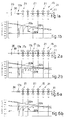
- Fig.1a is a diagram of a finishing train of a known plant producing strip from thin slabs, the train comprising in this case six finishing stands, with an emergency shears and a descaling unit positioned upstream of the train.
- the bar reaches the inlet of the finishing train with a thickness of at least 40 mm. and with an intake speed between about 20 and 35 metres per minute.
- Fig.1b is a diagram of the development of the surface, internal and mean temperatures respectively of the bar in the finishing train of Fig.1a.
- Fig.1c shows a plant of the type "A", in which can be seen, in sequence and in a rough sketch, a mould with a relative continuous casting plant for thin slabs, a shears which shears to size the thin slab leaving the continuous casting plant, a heating furnace five times as long as the length of the sheared slab, a shears for service shearing, a finishing train consisting of six four-high rolling mill stands and a finishing treatment segment.
- Fig.1d shows a plant of the type "B", in which can be seen, in sequence and in a rough sketch, a mould with a relative continuous casting plant for thin slabs, this continuous casting plant including a treatment of soft-reduction of the thin slab, two roughing rolling mill stands, an emergency shears, a winding unit, another emergency shears, a finishing assembly consisting of four rolling mill stands and a finishing treatment segment.
- the roughing rolling mill stands receive a thin slab with a thickness of about 40-45 mm. and therefore work very badly.
- US-A-5,235,840 arranges that a continuous, intense removal of scale is carried on so as to eliminate from the surface of the bar the hard scale of iron oxides so that such scale does not affect the final result of the rolling.
- Fig.2a Such a lay-out is shown in Fig.2a and the relative diagram of the temperatures is shown in Fig.2b.
- This teaching provides for elimination of the scale, which forms after the conventional descaling unit, immediately upstream of the rolling mill stands of the finishing train by means of appropriate auxiliary descaling units.
- these plants entail the problem that the slab enters the finishing rolling mill at a very low speed, which produces an outgoing bar with a poor surface quality, and the bar may have the scale impressed on its surface.
- the small size of the storage area causes the need, where the downstream line is halted, to send for scrap the slabs produced by the continuous casting plant or else to halt the continuous casting plant itself.
- Document EP-A-0 320 846 shows an apparatus and method for hot-rolling slabs having a thickness of 80-220 mm. into sheets having a thickness of 1,7-2,5 mm., wherein a rough rolling mill and a finish rolling mill are disposed in sequence so as to successively roll a slab material.
- a furnace is also provided to heat the slabs, but such a furnace has not the specific function to eliminate surface defects of slabs by means of the formation of scale, so that the furnace solely performs those functions which are normally known.
- Document JP-A- 57-202952 shows a controller for continuous casting of molten metal, wherein a plurality of detectors detect the position of molten metal, the position of molten powder, the position of powder layer, the thickness of a slag film and the surface temperature of an ingot to transmit signals to a signal processor which determines the charging rate, the charging time of the powder and other information for the continuous casting.
- a signal processor which determines the charging rate, the charging time of the powder and other information for the continuous casting.
- Document JP-A- 59-21457 shows a detector for detecting the lubricating conditions between a casting mould and a continuous casting billet and a signal processor which control the casting. Also in this document no reference is made to the control of the plant downstream of the continuous casting.
- Document WO-A- 89/11363 shows a process and a plant for continuous production of steel strip from flat products made by the circular-arc type continuous casting process wherein the flat product is deformed, inductively re-heated in a furnace and further deformed. Also in this plant, the furnace does not perform any elimination of surface defects of the flat product.
- the purpose of the invention is to provide a method to produce strip, starting from thin slabs, the method enabling a finished product of a high quality to be obtained.
- the method according to the invention arranges to take corrective action on the configuration of the mould, on the casting method, on the method of feed of the thin slab in the heating furnace and on the rolling method so as to produce a finished strip having a high, desired, intrinsic surface quality.
- the continuous casting of the thin slab is carried on at a speed relatively lower than that of a continuous casting with a thin slab 40-60 mm. thick inasmuch as the thin slab leaving the crystalliser has relatively great thicknesses between 70 and 100 mm.
- This contrivance makes it possible to have a casting chamber in the crystalliser with an ample surface and with great volumes, thus reducing the turbulence of the molten metal, improving the melting of the lubricating protective powders and improving the uniformity of the temperature and control thereof in the crystalliser itself.
- the better melting of the powders optimises their lubricating effect between the sidewall of the crystalliser and the forming skin of the thin slab. Moreover the proper control of the temperature improves the product.
- a mould can be used advantageously which is of a type having movable sidewalls to adjust the width of the thin slab, the casting chamber of the mould extending along the longitudinal length of the mould and including a lateral enlargement at least in one long sidewall.
- the lateral enlargement may be constant along the whole length of the casting chamber or may decrease substantially progressively in the lengthwise and/or transverse directions as it proceeds towards the outlet of the crystalliser.
- the mould may have a terminal segment with a constant cross-section.
- a mould of this type with a lateral enlargement makes possible a still more ample meniscus and thus improves the melting capacity of the lubricating powders; moreover, the great volume of molten metal thus produced lessens the turbulence and obviates the incorporation of powders and slag in the thin slab, thus improving the quality of the thin slab produced.
- the oscillation of the mould is brought about intentionally with a hydraulic system so that it can be adjusted continuously during the casting as regards its amplitude, frequency and waveform, depending on a plurality of casting parameters, (speed, temperature, types of steel, etc.).
- the oscillation of the mould is carried out according to an asymmetric cycle by having a very high speed of lowering of the mould and a lower speed of re-ascent of the mould.
- This oscillation cycle causes a sharp descent of the mould and a slow reascent, thus improving release of the slab.
- the method according to the invention arranges also to deliver the thin slab leaving the continuous casting plant into a furnace, which at least maintains the temperature of the slab and may even heat the slab during a stay time such as will produce the desired thickness of scale, this thickness of scale being intentionally correlated with the depth of the surface micro-defects in the thin slab.
- the method according to the invention provides for the first rolling step in the roughing train to be carried out so as to produce a bar which, when rolled in the finishing train, enables parameters of thickness, speed of feed and surface temperature to be used which are such as to prevent the formation of scale with hard, fragile oxides.
- the method according to the invention therefore makes it possible, on the one hand, to reduce wear and abrasion of the rolls of the stands of the finishing train and, on the other hand, to prevent the produced scale from creating surface defects on the strip.
- the method according to the invention frees the roughing step from depending on the continuous casting process, in which the thin slab moves forward at a speed between 2 and 10 metres per minute, and carries out the step of roughing the thin slab at an optimum rolling speed of about 1.3 to 4 metres per second when leaving the roughing rolling stands.
- the bar leaving the roughing train has a thickness between 16 and 40 mm., but advantageously 20-25 mm.
- the bar with a maximum thickness of 40 mm. is then introduced into the finishing train at an intake speed between 30 and 85 metres per minute, depending on the intended finished thickness of the strip and the intake thickness of the bar entering the finishing train.
- the bar leaving the roughing train undergoes a descaling step, which also brings its surface temperature down to about 700°C.
- the surface temperature of the bar being rolled in the finishing train is substantially always between 700° and 930°C, with the result that the reduced quantity of the scale formed consists essentially of malleable oxides such as FeO.
- the method to produce strip according to the invention is of a continuous type, and the bar leaving the roughing train and therefore entering the finishing assembly cooperates with temperature-maintaining means consisting of a suitably insulated tunnel furnace equipped with burners to maintain the temperature of the bar.
- This tunnel furnace also may have the purpose of increasing the temperature of the bar.
- the tunnel furnace advantageously includes a hood which can be opened to facilitate access to the bar being processed in the event of an obstruction downstream;
- the method to produce strip according to the invention is of a type with a head-to-tail inversion of the bar leaving the roughing train and provides for the bar to be introduced into a coil box, in which the bar is wound to form a coil before being sent to the finishing train.
- the coil box includes advantageously a winding station and an unwinding station so as to make possible at the same time the winding of a new coil and the unwinding of the coil just completed so as to feed the downstream finishing train.
- the production plant according to the invention comprises other auxiliary units such as, for instance, measurement units at the roughing train and/or finishing train.
- These measurement units have the task of checking the temperature, thickness, width and flatness of the slab and strip as well as the transverse profile of the strip so as to ensure by means of the relative checking systems that the outgoing product is of a quality possessing the desired properties.
- the strip leaving the finishing train is sent advantageously to a strip-coiling unit for production of coils, which are then removed from the plant.
- the whole system is controlled and managed by a data processing assembly structured with a plurality of specialised data processing units divided into a plurality of differentiated levels of management and interacting on the basis of those different levels.
- This data processing assembly controls not only the temperature of the slab and the working conditions of the various components of the plant such as speed and temperature but also controls the development of the cycle, storing anomalies in the extraction of the slab from the crystalliser, imperfect adjustments of the machines and/or of the furnaces, lack of working continuity and any other faults which may affect the finished result.
- the reference number 10 in the attached figures denotes generally a plant to produce strip, starting from thin slabs 29, according to the invention.
- the production plant 10 enables strip 11 to be produced from a plant 12 continuously casting thin slabs 29, the strip 11 having an excellent surface quality.
- the method according to the invention arranges to cast at a speed suitable to produce a thin slab 29 of a thickness between 70 mm. and 100 mm., this low casting speed being between 2 and 10 metres per minute.
- the mould is associated with a hydraulic oscillation unit, which subjects the mould to an oscillatory action, the parameters of which, such as amplitude, frequency and waveform, are at least correlated with the casting parameters, such as casting speed and temperature.
- all the parameters of the oscillation of the mould such as amplitude and frequency of oscillation and waveform, can be adjusted continuously during the casting according to the casting speed and temperature and the grade of the steel.
- the mould is caused to oscillate advantageously so as to have a speed of descent much greater than its speed of reascent, as is shown in the diagram of Fig.7 as an example.
- the invention arranges that a shearing unit 26 is included downstream of the continuous casting plant 12 and shears to size the emerging thin slab 29.
- the method according to the invention arranges to carry out rolling steps in the rolling assemblies, namely a roughing assembly 14 and a finishing assembly 15 respectively, at high speeds of feed of bars 30 having a modest thickness.
- the production plant 10 enables the roughing step to be carried out on a thin slab 29 travelling at a speed of about 1.3 to 4 metres per second when leaving the roughing stand and makes it possible to have a bar 30 of a thickness between 16 and 40 mm., but advantageously between 20 and 25 mm., at the inlet of the finishing train 15.
- the above two features enable a strip 11 to be produced with a minimum formation of scale and the surface temperature of the bar 30 within the finishing train 15 to be kept between 700° and 930°C, with a resulting formation of scale consisting mainly of malleable oxides such as FeO.
- the strip 11 produced by the method according to the invention is therefore of a high quality and substantially free of surface faults.
- the production plant 10 is of a continuous type (Fig.3), whereas according to a second lay-out of the invention the production plant 110 includes a head-to-tail inversion of the bar 30 (Fig.4).
- the continuous production plant 10 comprises a continuous casting plant 12 consisting in this case of two parallel continuous casting units, each of which is upstream of a temporary store 13 for thin slabs 29 (or else upstream of a furnace performing the task of a heating furnace or a temperature-maintaining furnace), the length of the temporary store 13 being about four to five times the length of the sheared slab.
- the continuous casting plant 12 consists of one single casting unit.
- a temperature detector is included downstream of the continuous casting plant 12; a unit to detect the temperature of the molten metal may be provided in cooperation with the crystalliser.
- the store 13 enables the roughing assembly 14 to be freed from depending on the upstream continuous casting plant 12 and the roughing step to be therefore carried out at the desired speed.
- a shearing unit 26 suitable, if so required, to shear the sheared slabs to a shorter size.
- a furnace 16 able at least to maintain the temperature of the thin slabs 29 is included downstream of the continuous casting plant 12 so as to increase the flexibility of the plant and to prevent any downtimes of the plant 10 in the event of accidents occurring upstream or downstream of the furnace 16.
- This furnace 16 may make possible an axial feed of the thin slabs 29 or a feed at a right angle to the lengthwise axis of the thin slabs 29.
- this at least temperature-maintaining furnace 16 enables the stay time of the thin slab 29 to be increased with a resulting formation of a scale having a thickness correlated with the depth of the micro-faults in the surface of the thin slab 29.
- this at least temperature-maintaining furnace 16 makes it possible to act by temperature and stay-time on the thin slab 29 according to the casting temperature or to the temperature of the thin slab 29 or to the composition of the steel alloy.
- the thin slab 29 Downstream of the at least temperature-maintaining furnace 16 the thin slab 29 cooperates with a roughing assembly 14 comprising a vertical rolling mill stand and two horizontal rolling mill stands in this case.
- the roughing assembly 14 comprises horizontal stands alone.
- the roughing assembly 14 comprises a horizontal rolling mill stand and a vertical rolling mill stand.
- the thin slab 29 cooperates, upstream of the roughing assembly 14, with a first descaling unit 17a and with a possible measurement unit 18.
- the measurement unit 18 is shown downstream of the roughing assembly 14.
- the thin slab 29 is rolled on its sides by vertical rolling mill stands upstream of the first descaling unit 17a
- the bar 30 cooperates, downstream of the roughing assembly 14, with a tunnel furnace 23 containing an insulated roller conveyor 19 to maintain the temperature of the bar 30.
- the tunnel furnace 23 contains advantageously a plurality of temperature-maintaining burners 20 and may include a movable hood system to facilitate access to the roller conveyor 19 for maintenance work or to remove the bar 30 in the event of an obstruction.
- the bar 30 then cooperates with the finishing assembly 15, which generally comprises from four to seven horizontal rolling mill stands 21 to roll the bar 30 until a strip 11 of the desired thickness has been produced.
- the finishing assembly 15 generally comprises from four to seven horizontal rolling mill stands 21 to roll the bar 30 until a strip 11 of the desired thickness has been produced.
- an emergency shears 26 is included at the inlet of the finishing assembly 15 to shear the bar 30 in the event of accidents and/or breakdowns.
- This emergency shears 26 also performs the cutting of the normal slabs into desired portions so as to obtain two or more coils of a reduced weight.
- the bar 30 entering the finishing assembly 15 has a thickness between 16 and 40 mm., but advantageously between 20 and 25 mm.
- At least one second descaling unit 17b positioned upstream of the finishing assembly 15 is included with the function of descaling and with the function of keeping the surface temperature of the bar 30 within the optimum range of 700°C-930°C.
- the finishing assembly 15 shown in Fig.2a is of the type disclosed in US-A-5,235,840 and includes a plurality of auxiliary descaling units 17c positioned between one rolling mill stand 21 and the next one to carry out an intense and substantially continuous action to remove scale; this plant entails the shortcomings disclosed in the state of the art.
- Fig.6a shows as an example a diagram of a finishing assembly 15 of a plant 10 to produce strip 11 from thin slabs 29 according to the invention; in this case the finishing assembly 15 comprises six rolling mill stands 21 installed downstream of the second descaling unit 17b.
- Fig.6b shows a possible development of the internal 22a, surface 22b and, with lines of dashes, mean 22c temperatures respectively of the bar 30.
- the strip 11 leaving the finishing assembly 15 slides on a removal roller conveyor 24, which feeds the strip 11 to a winding unit 25.
- the tunnel furnace 23 is replaced by a coil box 27, in which there takes place the head-to-tail inversion of the bar 30 leaving the roughing train 14 before being fed to the finishing train 15.
- a shearing unit 26 is included upstream and/or downstream of the coil box 27 and has the task of an emergency shears and of shearing the bar 30 to shorter lengths.
- the coil box 27 includes advantageously a winding station 28a and an unwinding station 28b, with which a transfer unit cooperates in transferring the wound coil from the winding station 28a to the unwinding station 28b.
- the coil after having been completely wound in the winding station 28a, is transferred to the unwinding station 28b, where the unwinding step begins.
- the unwinding step begins and the coil is then transferred to the unwinding station 28b where the unwinding continues, while a new bar 30 can be wound in the winding station 28a.
- Fig.5 shows a plant 210 in which two continuous casting units 12 are positioned at the opposite sides of the at least temperature-maintaining furnace 16, while the rolling line is substantially located on the median line of the at least temperature-maintaining furnace 16.
- the plant 10-110-210 includes a data processing assembly 31 structured with a plurality of data processing units possessing differentiated levels of management, the data processing assembly 31 being associated with a plurality of detectors such as a casting speed detector, a detector for the temperature of the molten metal in the mould, a detector for the temperature of the sidewall of the crystalliser, a detector of surface faults on the thin slab 29, a detector for the temperature of the thin slab 29, detectors of the speed of feed and temperature of the temporary store 13, detectors of the speed of feed and temperature of the at least temperature-maintaining furnace 16, detectors of the speed of feed and temperature of the tunnel furnace 23, detectors of the rolling pass (adjustment) and speed of feed of the roughing assembly 14 and of the machines associated therewith, detectors of the rolling pass (adjustment) and speed-of feed of the finishing assembly 15 and of the machines associated therewith.
- the data processing assembly 31 being associated with a plurality of detectors such as a casting speed detector, a detector for the temperature of the mol
- the data processing assembly 31 can contain a plurality of maps or files which relate the type of steel to the casting and processing characteristics and determine statistically, with a high degree of reliability, the characteristics or type of the working parameters at each point of the plant.
- the data processing assembly 31 performs a plurality of functions including:
- the data processing assembly 31 as it consists of a plurality of data processing units specialised in specific functions and interacting with each other on the basis of differentiated interactive levels of management, enables the path of the product leaving the crystalliser to be followed in its various transformations until it becomes the finished product.
- This system enables the data processing assembly 31 to obtain information, to create new data storages, to rebalance the process and to act upstream when situations downstream make necessary some modifications of the upstream process.
- the data processing assembly 31 by storing anomalies at various points and momentary anomalies of this or that furnace or of this or that machine, is able to take action in the downstream passes to eliminate or at least to reduce considerably the qualitative faults which such anomaly or anomalies entail in the finished product.
Landscapes
- Engineering & Computer Science (AREA)
- Mechanical Engineering (AREA)
- Metal Rolling (AREA)
- Compositions Of Macromolecular Compounds (AREA)
- Belt Conveyors (AREA)
- Yarns And Mechanical Finishing Of Yarns Or Ropes (AREA)
- Heat Treatment Of Sheet Steel (AREA)
- Diaphragms For Electromechanical Transducers (AREA)
- Continuous Casting (AREA)
Claims (19)
- Verfahren zur Herstellung von Bandstahl (11), bei dem von mittels einer Stranggußanlage (12) hergestellten dünnen Brammen (29) ausgegangen wird, wobei die dünne Bramme (29) außerdem einem einzelnen Entzunderungsschritt unterliegt, auf den ein Vorwalzschritt und ein Fertigwalzschritt folgen, bevor sie zu Rollen aufgewickelt wird, dadurch gekennzeichnet, daß die Kokille einem Oszillationsvorgang unterzogen wird, dessen Feststellung teilweise mit den Gußparametern in Wechselbeziehung steht, die zumindest die Geschwindigkeit, Temperatur und Struktur des Stahls einschließen, und daß die die Kristallisationseinrichtung der Stranggußanlage (12) verlassende dünne Bramme (29) eine Dicke von 70 bis 100 mm aufweist und sich mit einer Geschwindigkeit von 2 bis 10 Meter pro Sekunde bewegt, wobei die die Kristallisationseinrichtung verlassende dünne Bramme (29) dem Schritt einer sanften Dickenabnahme unterzogen wird und vor dem Vorwalzschritt für eine Zeitspanne, die zumindest mit den Kennwerten der Oberflächendefekte der dünnen Bramme (29) in Wechselbeziehung steht, in einem die Temperatur aufrechterhaltenden Ofen (16) gelassen wird und der Vorwalzschritt mit einer abgehenden Geschwindigkeit von etwa 1,3 bis 4 Meter pro Sekunde erfolgt, damit als Ausstoß eine Walzader (30) mit einer Dicke von 16 bis 40 mm erzeugt wird, wohingegen der Fertigwalzschritt abhängig von der Fertigdicke des Bandstahls (11) und der Dicke der Walzader (30) mit einer Geschwindigkeit von 30 bis 85 Meter pro Sekunde begonnen wird, wobei jeder Verfahrensschritt durch Erfassungseinrichtungen gesteuert und von einem Datenverarbeitungsaufbau (31) verwaltet wird, der sich aus einer Vielzahl von voneinander abgegrenzten Verwaltungsebenen aufbaut.
- Verfahren nach Anspruch 1, wobei das Wirken der der Kokille zugeordneten Oszillationseinheit einer hydraulischen Bauart von einem Datenverarbeitungsaufbau (31) reguliert wird und Einrichtungen zugeordnet ist, die die Gießgeschwindigkeit und die Temperatur der Metallschmelze in der Kokille erfassen, wobei der Datenverarbeitungsaufbau (31) die folgenden Oszillationsparameter bestimmt, die von der Oszillationseinheit auf die Kokilie gegeben werden: Frequenz, Amplitude und Wellenform.
- Verfahren nach einem der vorstehenden Ansprüche, wobei die Bewegungsgeschwindigkeit der dünnen Bramme (29) in dem die Temperatur aufrechterhaltenden Ofen (16) von dem Datenverarbeitungsaufbau (31) gesteuert wird, dem zumindest ein System zum Erfassen/Festlegen von Oberflächenfehlern auf der dünnen Bramme (29) und/oder der Art und Qualität des Stahls zugeordnet ist.
- Verfahren nach einem der vorstehenden Ansprüche, wobei zwischen der Stranggußanlage (12) und dem die Temperatur aufrechterhaltenden Ofen (16) zwecks Aufrechterhalten oder Erhöhen der Temperatur ein Zwischenspeicher (13) eingefügt ist.
- Verfahren nach einem der vorstehenden Ansprüche, wobei die Dicke der den vorwalzaufbau (14) verlassenden Walzader (30) 20 bis 25 mm beträgt.
- Verfahren nach einem der vorstehenden Ansprüche, wobei die den Vorwalzaufbau (14) verlassende Walzader (30) einem Entzunderungsschritt unterliegt, um zumindest ihre Oberflächentemperatur auf etwa 700°C zu senken.
- Verfahren nach einem der vorstehenden Ansprüche, wobei die Walzader (30) zwischen dem Vorwalzaufbau (14) und dem Fertigwalzaufbau (15) mittels eines Bundkastens (27) umgekehrt wird.
- Anlage zur Herstellung von Bandstahl (11), wobei von dünnen Brammen (29) ausgegangen wird, die mittels einer Stranggußanlage (12) hergestellt werden, die eine eine Kristallisationseinrichtung mit einer Auslaßdicke von 70 bis 100 mm umfassende Kokille aufweist, und wobei die Anlage einen die Temperatur zumindest aufrechterhaltenden Ofen (16), einen an seinem Auslaß eine 16 bis 40 mm dicke Walzader (30) erzeugenden Vorwalzaufbau (14) und einen stromabwärts von dem Vorwalzaufbau (14) befindlichen Fertigwalzaufbau (15) umfaßt, dadurch gekennzeichnet, daßwobei der Datenverarbeitungsaufbau (31) eine Vielzahl von spezialisierten Datenverarbeitungseinheiten umfaßt, die auf voneinander abgegrenzten Verwaltungsebenen zusammenwirken und denen eine Vielzahl von Erfassungseinrichtungen zur kontinuierlichen Steuerung der Anlage gemäß den von den Erfassungseinrichtungen erfaßten Parametern zugeordnet sind.der Kokille eine hydraulische Oszillationseinheit und eine Einrichtung zur sanften Dickenabnahme zugeordnet ist,ein Datenverarbeitungsaufbau (31) bereitgestellt ist, um die hydraulische Oszillationseinheit zu verwalten und um die Verweilzeit der dünnen Bramme (29) in dem die Temperatur zumindest aufrechterhaltenden Ofen (16) gemäß den Oberflächendefekten der dünnen Bramme (29) zu bestimmen, undden verschiedenen Komponenten der Anlage eine Vielzahl von Erfassungseinrichtungen zugeordnet ist, um deren Arbeitsparameter wie beispielsweise Vorschubgeschwindigkeit der Brammen, Temperatur und Oberflächenfehler der Brammen zu erfassen,
- Anlage zur Herstellung von Bandstahl (11) nach Anspruch 8, bei der die hydraulische Oszillationseinheit Einrichtungen zum Festsetzen der folgenden Oszillationsparameter umfaßt:Amplitude der Oszillation,Frequenz der Oszillation,Wellenform.
- Anlage zur Herstellung von Bandstahl (11) nach Anspruch 8 oder 9, bei der dem Datenverarbeitungsaufbau (31) eine Einrichtung zum Erfassen der Gießgeschwindigkeit und eine Einrichtung zum Erfassen der Temperatur der Metallschmelze in der Kokille zugeordnet sind.
- Anlage zur Herstellung von Bandstahl (11) nach einem der Ansprüche 8 bis 10, bei der der Kristallisationseinrichtung eine Vielzahl von zur Verhinderung eines Durchbruchs geeigneten Temperaturerfassungseinrichtungen zugeordnet ist.
- Anlage zur Herstellung von Bandstahl (11) nach einem der Ansprüche 8 bis 11, bei der die den Vorwalzaufbau (14) verlassende Walzader (30) eine Dicke von 20 bis 25 mm aufweist.
- Anlage zur Herstellung von Bandstahl (11) nach einem der Ansprüche 8 bis 12, bei der unmittelbar stromabwärts von der Stranggußanlage (12) eine Schereinheit (26) eingefügt ist.
- Anlage zur Herstellung von Bandstahl (11) nach einem der Ansprüche 8 bis 13, bei der zwischen der Stranggußanlage (12) und dem die Temperatur aufrechterhaltenden Ofen (16) ein Zwischenspeicher (13) eingefügt ist, der eine 4- bis 5-mal so große Länge wie die abgescherte dünne Bramme (29) aufweist.
- Anlage zur Herstellung von Bandstahl (11) nach einem der Ansprüche 8 bis 14, die eine Stranggußanlage (12) mit sanfter Dickenabnahme, eine Schereinheit (26), einen Zwischenspeicher (13), einen die Temperatur aufrechterhaltenden Ofen (16), einen Vorwalzaufbau (14) und einen Fertigwalzaufbau (15) umfaßt.
- Anlage zur Herstellung von Bandstahl (11) nach einem der Ansprüche 8 bis 15, bei der zwischen dem Vorwalzaufbau (14) und dem Fertigwalzaufbau (15) ein die Temperatur aufrechterhaltender Tunnelofen (23) eingefügt ist.
- Anlage zur Herstellung von Bandstahl (11) nach einem der Ansprüche 8 bis 16, bei der stromabwärts von dem Vorwalzaufbau (14) und stromaufwärts von dem Fertigwalzaufbau (15) ein Bundkasten (27) zur Umkehrung von Kopf- und Endabschnitt eingefügt ist.
- Anlage zur Herstellung von Bandstahl (11) nach einem der Ansprüche 8 bis 17, bei der der die Temperatur aufrechterhaltende Tunnelofen (23) Brenner (20) aufweist.
- Anlage zur Herstellung von Bandstahl (11) nach einem der Ansprüche 8 bis 18, bei der der Datenverarbeitungsaufbau (31) eine Vielzahl von spezialisierten Datenverarbeitungseinheiten umfaßt, die auf der Grundlage voneinander abgegrenzter Verwaltungsebenen gesteuert werden.
Applications Claiming Priority (2)
| Application Number | Priority Date | Filing Date | Title |
|---|---|---|---|
| ITUD940051 | 1994-03-31 | ||
| IT94UD000051A IT1267916B1 (it) | 1994-03-31 | 1994-03-31 | Procedimento per la produzione di nastro partendo da bramme sottili e relativo impianto |
Publications (2)
| Publication Number | Publication Date |
|---|---|
| EP0674952A1 EP0674952A1 (de) | 1995-10-04 |
| EP0674952B1 true EP0674952B1 (de) | 1999-02-10 |
Family
ID=11421553
Family Applications (1)
| Application Number | Title | Priority Date | Filing Date |
|---|---|---|---|
| EP95102881A Expired - Lifetime EP0674952B1 (de) | 1994-03-31 | 1995-03-01 | Verfahren zur Herstellung von Bandstahl, ausgehend von dünnen Bramen, und entsprechende Anlage |
Country Status (8)
| Country | Link |
|---|---|
| US (1) | US5528816A (de) |
| EP (1) | EP0674952B1 (de) |
| CN (1) | CN1114244A (de) |
| AT (1) | ATE176610T1 (de) |
| BR (1) | BR9501306A (de) |
| DE (1) | DE69507729T2 (de) |
| ES (1) | ES2126801T3 (de) |
| IT (1) | IT1267916B1 (de) |
Cited By (1)
| Publication number | Priority date | Publication date | Assignee | Title |
|---|---|---|---|---|
| AU2005297538B2 (en) * | 2004-10-13 | 2010-07-01 | Primetals Technologies Austria GmbH | Method and device for continuously producing a thin metal strip |
Families Citing this family (21)
| Publication number | Priority date | Publication date | Assignee | Title |
|---|---|---|---|---|
| IT1281420B1 (it) * | 1995-09-13 | 1998-02-18 | Danieli Off Mecc | Procedimento di equalizzazione in un forno di riscaldo con ambiente ad ossidazione controllata e forno di riscaldo |
| IT1281442B1 (it) * | 1995-10-27 | 1998-02-18 | Danieli Off Mecc | Procedimento di laminazione per nastri e lamiere e linea di laminazione che concretizza tale procedimento |
| IT1288863B1 (it) * | 1996-03-15 | 1998-09-25 | Danieli Off Mecc | Procedimento di laminazione in continuo per lamiere e/o nastri e relativa linea di laminazione in continuo |
| NL1003293C2 (nl) * | 1996-06-07 | 1997-12-10 | Hoogovens Staal Bv | Werkwijze en inrichting voor het vervaardigen van een stalen band. |
| IT1289036B1 (it) * | 1996-12-09 | 1998-09-25 | Danieli Off Mecc | Linea di colata continua compatta |
| CA2229255C (en) * | 1997-04-16 | 2002-01-08 | Danieli Technology, Inc. | Long slab rolling process and apparatus |
| AT407348B (de) * | 1997-10-10 | 2001-02-26 | Voest Alpine Ind Anlagen | Verfahren zum herstellen eines warmgewalzten produktes und anlage zur durchführung des verfahrens |
| WO2000051755A1 (en) * | 1999-03-04 | 2000-09-08 | Pohang Iron & Steel Co., Ltd. | Method of manufacturing hot rolled steel sheet using mini mill process |
| KR100368253B1 (ko) | 1997-12-09 | 2003-03-15 | 주식회사 포스코 | 미니밀프로세스에의한열연판의제조방법 |
| AT409227B (de) * | 1998-08-17 | 2002-06-25 | Voest Alpine Ind Anlagen | Verfahren und anlage zur herstellung von warmgewalztem stahlband aus einer stahlschmelze |
| DE19843033B4 (de) * | 1998-09-19 | 2017-11-09 | Sms Group Gmbh | Durchbrucherkennungsverfahren für eine Stranggießkokille |
| US6336980B1 (en) | 1999-05-21 | 2002-01-08 | Danieli Technology, Inc. | Method for in-line heat treatment of hot rolled stock |
| DE10047044A1 (de) * | 2000-09-22 | 2002-04-25 | Sms Demag Ag | Verfahren und Anlagen zum Herstellen von Bändern und Blechen aus Stahl |
| US20120018113A1 (en) * | 2004-12-03 | 2012-01-26 | Joachim Schwellenbach | CSP-continuous casting plant with an additional rolling line |
| CN100404149C (zh) * | 2005-05-20 | 2008-07-23 | 唐山钢铁股份有限公司 | 一种薄板坯C-Mn板带钢的生产工艺 |
| DE102006004688A1 (de) * | 2006-02-02 | 2007-08-16 | Sms Demag Ag | Verfahren und Giess-Walz-Anlage zum Herstellen von warmgewalztem Metall - insbesondere Stahlwerkstoff-Band mit hoher Oberflächengüte |
| EP2386365A1 (de) * | 2010-05-06 | 2011-11-16 | Siemens Aktiengesellschaft | Betriebsverfahren für eine Fertigstraße mit Prädiktion der Leitgeschwindigkeit |
| RU2465081C1 (ru) * | 2011-06-24 | 2012-10-27 | Открытое акционерное общество Акционерная холдинговая компания "Всероссийский научно-исследовательский и проектно-конструкторский институт металлургического машиностроения имени академика Целикова" (ОАО АХК "ВНИИМЕТМАШ") | Способ производства листовой холоднокатаной продукции из алюминия и его сплавов |
| TWI462783B (zh) * | 2011-09-08 | 2014-12-01 | China Steel Corp | Steel surface rusting device |
| DE102013220657A1 (de) * | 2013-07-26 | 2015-01-29 | Sms Siemag Ag | Verfahren und Vorrichtung zur Herstellung eines metallischen Bandes im kontinuierlichen Gießwalzverfahren |
| DE102017210850A1 (de) * | 2016-11-17 | 2018-05-17 | Sms Group Gmbh | Ofen zum Erwärmen von Metallbändern, und Vorrichtung und Verfahren zur Herstellung von Metallbändern im Gießwalzverfahren |
Family Cites Families (18)
| Publication number | Priority date | Publication date | Assignee | Title |
|---|---|---|---|---|
| JPS5722A (en) * | 1980-05-29 | 1982-01-05 | Tokyo Shibaura Electric Co | Distance relay |
| JPS57202952A (en) | 1981-06-04 | 1982-12-13 | Nippon Steel Corp | Controller for continuous casting of molten metal |
| JPS5832506A (ja) * | 1981-08-21 | 1983-02-25 | Kawasaki Steel Corp | 微弱酸化熱間圧延方法 |
| JPS5921457A (ja) | 1982-07-29 | 1984-02-03 | Nippon Steel Corp | 連鋳鋳型内で発生する鋳片表面欠陥の検出装置 |
| US4630352A (en) * | 1984-09-04 | 1986-12-23 | Tippins Machinery Company, Inc. | Continuous rolling method and apparatus |
| JPS6289502A (ja) * | 1985-10-12 | 1987-04-24 | Sumitomo Metal Ind Ltd | 薄鋳片連続鋳造による鋼板の製造法 |
| US4675974A (en) * | 1985-10-17 | 1987-06-30 | Tippins Machinery Co., Inc. | Method of continuous casting and rolling strip |
| DE3543790A1 (de) * | 1985-12-09 | 1987-06-11 | Mannesmann Ag | Oszillationsvorrichtung |
| JP2585529B2 (ja) * | 1986-04-14 | 1997-02-26 | 株式会社日立製作所 | 高温の薄板鋳片を減厚圧延する方法及び装置 |
| EP0264459B1 (de) * | 1986-10-13 | 1989-09-20 | Sms Schloemann-Siemag Aktiengesellschaft | Herstellung von warmgewalztem Stahlband aus stranggegossenen Brammen |
| DE3637893C2 (de) * | 1986-11-06 | 1996-02-08 | Schloemann Siemag Ag | Verfahren und Anlage zur Herstellung von warmgewalztem Stahlband und Bandgießanlage |
| JPS63252604A (ja) * | 1987-04-08 | 1988-10-19 | Hitachi Ltd | 連鋳直結圧延方法及び装置 |
| AU2669088A (en) | 1987-12-18 | 1989-06-22 | Hitachi Limited | Apparatus and method for hot-rolling slab into sheets |
| IT1224318B (it) | 1988-05-26 | 1990-10-04 | Mannesmann Ag | Processo ed impianto per la produzione continua di nastro di acciaio |
| JP3152241B2 (ja) * | 1990-06-12 | 2001-04-03 | 株式会社日立製作所 | 熱間薄板製造設備及び製造方法 |
| IT1244295B (it) * | 1990-07-09 | 1994-07-08 | Giovanni Arvedi | Processo ed impianto per l'ottenimento di nastri di acciaio avvolti, aventi caratteristiche di laminati a freddo ottenuti direttamente in linea di laminazione a caldo |
| NL9100911A (nl) * | 1991-03-22 | 1992-10-16 | Hoogovens Groep Bv | Inrichting en werkwijze voor het vervaardigen van warmgewalst staal. |
| US5235840A (en) | 1991-12-23 | 1993-08-17 | Hot Rolling Consultants, Ltd. | Process to control scale growth and minimize roll wear |
-
1994
- 1994-03-31 IT IT94UD000051A patent/IT1267916B1/it active IP Right Grant
-
1995
- 1995-03-01 AT AT95102881T patent/ATE176610T1/de not_active IP Right Cessation
- 1995-03-01 ES ES95102881T patent/ES2126801T3/es not_active Expired - Lifetime
- 1995-03-01 DE DE69507729T patent/DE69507729T2/de not_active Expired - Fee Related
- 1995-03-01 EP EP95102881A patent/EP0674952B1/de not_active Expired - Lifetime
- 1995-03-16 US US08/405,194 patent/US5528816A/en not_active Expired - Fee Related
- 1995-03-30 BR BR9501306A patent/BR9501306A/pt not_active IP Right Cessation
- 1995-03-31 CN CN95103793.5A patent/CN1114244A/zh active Pending
Cited By (2)
| Publication number | Priority date | Publication date | Assignee | Title |
|---|---|---|---|---|
| AU2005297538B2 (en) * | 2004-10-13 | 2010-07-01 | Primetals Technologies Austria GmbH | Method and device for continuously producing a thin metal strip |
| AU2005297538B8 (en) * | 2004-10-13 | 2010-07-15 | Primetals Technologies Austria GmbH | Method and device for continuously producing a thin metal strip |
Also Published As
| Publication number | Publication date |
|---|---|
| DE69507729T2 (de) | 1999-07-22 |
| BR9501306A (pt) | 1995-10-31 |
| CN1114244A (zh) | 1996-01-03 |
| IT1267916B1 (it) | 1997-02-18 |
| DE69507729D1 (de) | 1999-03-25 |
| US5528816A (en) | 1996-06-25 |
| ITUD940051A0 (it) | 1994-03-31 |
| ES2126801T3 (es) | 1999-04-01 |
| EP0674952A1 (de) | 1995-10-04 |
| ATE176610T1 (de) | 1999-02-15 |
| ITUD940051A1 (it) | 1995-10-01 |
Similar Documents
| Publication | Publication Date | Title |
|---|---|---|
| EP0674952B1 (de) | Verfahren zur Herstellung von Bandstahl, ausgehend von dünnen Bramen, und entsprechende Anlage | |
| EP0594828B1 (de) | Verfahren und anlage zum stranggiessen von brammen mittlerer dicke und zum unmittelbar nachfolgenden herstellen von warmbändern und -blechen | |
| US5307864A (en) | Method and system for continuously producing flat steel product by the continuous casting method | |
| EP0625383B1 (de) | Produktionslinie zur Herstellung von Bändern und/oder Blechen | |
| RU2163934C2 (ru) | Способ изготовления горячекатаной стальной ленты и устройство для его осуществления | |
| US4675974A (en) | Method of continuous casting and rolling strip | |
| EP0795361B1 (de) | Verfahren zum kontinuierlichen Walzen von Blechen und/oder Bänder und entsprechende kontinuierliche Walzstrasse | |
| EP0504999B1 (de) | Vorrichtung und Verfahren zur Herstellung von warmgewalztem Stahl | |
| WO1993023182A9 (en) | Method and apparatus for intermediate thickness slab caster and inline hot strip and plate line | |
| CN109922904B (zh) | 铸造-轧制-复合设备和用于连续地制造热轧的成品带钢的方法 | |
| US4793401A (en) | Method of producing thin steel sheets having an improved processability | |
| JP4677097B2 (ja) | 熱間圧延薄板製品をエンドレス製造するための生産方法及び生産設備 | |
| US5630467A (en) | Thin slab continuous casting machine and method | |
| US7152661B2 (en) | Method and casting roller plant for the semi-endless or endlers rolling by casting of a metal in particular a steel strip which may be transversely separated as required after solidification | |
| CN110087801B (zh) | 用于在铸轧复合设备中连续制造卷绕的热轧带钢的方法 | |
| CN1466495A (zh) | 制造板带钢的方法及设备 | |
| CN101658860A (zh) | 一种薄板坯连铸连轧生产线 | |
| CN116887930A (zh) | 铸轧复合设备以及用于在所述铸轧复合设备上制造具有<1.2mm的最终厚度的热轧带的方法 | |
| CN1680051B (zh) | 一种薄板坯连铸连轧设备和方法 | |
| CN111420987A (zh) | 一种中宽带钢长距离连轧方法及轧线 | |
| RU2368438C2 (ru) | Компактная установка для получения горячекатаной стальной полосы | |
| CA2229255C (en) | Long slab rolling process and apparatus | |
| WO1995013149A1 (en) | Slab caster and inline strip and plate apparatus | |
| US12589423B2 (en) | Process and apparatus for producing metallurgical products, in particular of the merchant type, in particular in an endless mode | |
| AU658993B2 (en) | Method and apparatus for intermediate thickness slab caster and in-line hot strip and plate line |
Legal Events
| Date | Code | Title | Description |
|---|---|---|---|
| PUAI | Public reference made under article 153(3) epc to a published international application that has entered the european phase |
Free format text: ORIGINAL CODE: 0009012 |
|
| AK | Designated contracting states |
Kind code of ref document: A1 Designated state(s): AT BE DE ES FR GB IT SE |
|
| 17P | Request for examination filed |
Effective date: 19960326 |
|
| 17Q | First examination report despatched |
Effective date: 19970401 |
|
| GRAG | Despatch of communication of intention to grant |
Free format text: ORIGINAL CODE: EPIDOS AGRA |
|
| GRAG | Despatch of communication of intention to grant |
Free format text: ORIGINAL CODE: EPIDOS AGRA |
|
| GRAG | Despatch of communication of intention to grant |
Free format text: ORIGINAL CODE: EPIDOS AGRA |
|
| GRAH | Despatch of communication of intention to grant a patent |
Free format text: ORIGINAL CODE: EPIDOS IGRA |
|
| GRAH | Despatch of communication of intention to grant a patent |
Free format text: ORIGINAL CODE: EPIDOS IGRA |
|
| GRAA | (expected) grant |
Free format text: ORIGINAL CODE: 0009210 |
|
| AK | Designated contracting states |
Kind code of ref document: B1 Designated state(s): AT BE DE ES FR GB IT SE |
|
| REF | Corresponds to: |
Ref document number: 176610 Country of ref document: AT Date of ref document: 19990215 Kind code of ref document: T |
|
| ITF | It: translation for a ep patent filed | ||
| ET | Fr: translation filed | ||
| REF | Corresponds to: |
Ref document number: 69507729 Country of ref document: DE Date of ref document: 19990325 |
|
| REG | Reference to a national code |
Ref country code: ES Ref legal event code: FG2A Ref document number: 2126801 Country of ref document: ES Kind code of ref document: T3 |
|
| PLBQ | Unpublished change to opponent data |
Free format text: ORIGINAL CODE: EPIDOS OPPO |
|
| PLBI | Opposition filed |
Free format text: ORIGINAL CODE: 0009260 |
|
| PLBF | Reply of patent proprietor to notice(s) of opposition |
Free format text: ORIGINAL CODE: EPIDOS OBSO |
|
| 26 | Opposition filed |
Opponent name: SMS DEMAG AG Effective date: 19991110 |
|
| PLBF | Reply of patent proprietor to notice(s) of opposition |
Free format text: ORIGINAL CODE: EPIDOS OBSO |
|
| REG | Reference to a national code |
Ref country code: GB Ref legal event code: IF02 |
|
| PLBO | Opposition rejected |
Free format text: ORIGINAL CODE: EPIDOS REJO |
|
| PGFP | Annual fee paid to national office [announced via postgrant information from national office to epo] |
Ref country code: GB Payment date: 20020227 Year of fee payment: 8 |
|
| PGFP | Annual fee paid to national office [announced via postgrant information from national office to epo] |
Ref country code: SE Payment date: 20020306 Year of fee payment: 8 |
|
| PGFP | Annual fee paid to national office [announced via postgrant information from national office to epo] |
Ref country code: FR Payment date: 20020312 Year of fee payment: 8 |
|
| PGFP | Annual fee paid to national office [announced via postgrant information from national office to epo] |
Ref country code: AT Payment date: 20020313 Year of fee payment: 8 |
|
| PGFP | Annual fee paid to national office [announced via postgrant information from national office to epo] |
Ref country code: DE Payment date: 20020314 Year of fee payment: 8 |
|
| PGFP | Annual fee paid to national office [announced via postgrant information from national office to epo] |
Ref country code: ES Payment date: 20020315 Year of fee payment: 8 |
|
| PLBN | Opposition rejected |
Free format text: ORIGINAL CODE: 0009273 |
|
| STAA | Information on the status of an ep patent application or granted ep patent |
Free format text: STATUS: OPPOSITION REJECTED |
|
| PGFP | Annual fee paid to national office [announced via postgrant information from national office to epo] |
Ref country code: BE Payment date: 20020527 Year of fee payment: 8 |
|
| 27O | Opposition rejected |
Effective date: 20020125 |
|
| PG25 | Lapsed in a contracting state [announced via postgrant information from national office to epo] |
Ref country code: GB Free format text: LAPSE BECAUSE OF NON-PAYMENT OF DUE FEES Effective date: 20030301 Ref country code: AT Free format text: LAPSE BECAUSE OF NON-PAYMENT OF DUE FEES Effective date: 20030301 |
|
| PG25 | Lapsed in a contracting state [announced via postgrant information from national office to epo] |
Ref country code: SE Free format text: LAPSE BECAUSE OF NON-PAYMENT OF DUE FEES Effective date: 20030302 |
|
| PG25 | Lapsed in a contracting state [announced via postgrant information from national office to epo] |
Ref country code: ES Free format text: LAPSE BECAUSE OF NON-PAYMENT OF DUE FEES Effective date: 20030303 |
|
| PG25 | Lapsed in a contracting state [announced via postgrant information from national office to epo] |
Ref country code: BE Free format text: LAPSE BECAUSE OF NON-PAYMENT OF DUE FEES Effective date: 20030331 |
|
| BERE | Be: lapsed |
Owner name: *DANIELI & C. OFFICINE MECCANICHE S.P.A. Effective date: 20030331 |
|
| PG25 | Lapsed in a contracting state [announced via postgrant information from national office to epo] |
Ref country code: DE Free format text: LAPSE BECAUSE OF NON-PAYMENT OF DUE FEES Effective date: 20031001 |
|
| GBPC | Gb: european patent ceased through non-payment of renewal fee | ||
| EUG | Se: european patent has lapsed | ||
| PG25 | Lapsed in a contracting state [announced via postgrant information from national office to epo] |
Ref country code: FR Free format text: LAPSE BECAUSE OF NON-PAYMENT OF DUE FEES Effective date: 20031127 |
|
| REG | Reference to a national code |
Ref country code: FR Ref legal event code: ST |
|
| REG | Reference to a national code |
Ref country code: ES Ref legal event code: FD2A Effective date: 20030303 |
|
| PG25 | Lapsed in a contracting state [announced via postgrant information from national office to epo] |
Ref country code: IT Free format text: LAPSE BECAUSE OF NON-PAYMENT OF DUE FEES;WARNING: LAPSES OF ITALIAN PATENTS WITH EFFECTIVE DATE BEFORE 2007 MAY HAVE OCCURRED AT ANY TIME BEFORE 2007. THE CORRECT EFFECTIVE DATE MAY BE DIFFERENT FROM THE ONE RECORDED. Effective date: 20050301 |