EP0675229B1 - Eine Vorrichtung für das Auffangen von Leckflüssigkeiten - Google Patents
Eine Vorrichtung für das Auffangen von Leckflüssigkeiten Download PDFInfo
- Publication number
- EP0675229B1 EP0675229B1 EP95200759A EP95200759A EP0675229B1 EP 0675229 B1 EP0675229 B1 EP 0675229B1 EP 95200759 A EP95200759 A EP 95200759A EP 95200759 A EP95200759 A EP 95200759A EP 0675229 B1 EP0675229 B1 EP 0675229B1
- Authority
- EP
- European Patent Office
- Prior art keywords
- trough
- water
- grid
- liquids
- water discharge
- Prior art date
- Legal status (The legal status is an assumption and is not a legal conclusion. Google has not performed a legal analysis and makes no representation as to the accuracy of the status listed.)
- Expired - Lifetime
Links
Images


Classifications
-
- E—FIXED CONSTRUCTIONS
- E03—WATER SUPPLY; SEWERAGE
- E03F—SEWERS; CESSPOOLS
- E03F7/00—Other installations or implements for operating sewer systems, e.g. for preventing or indicating stoppage; Emptying cesspools
- E03F7/02—Shut-off devices
Definitions
- the invention relates to a device provided with a trough for catching leaking liquids.
- the invention furthermore relates to a parking plate for a vehicle provided with such a device.
- a device for catching leaking liquids is known from FR-A-2 659 096.
- Vehicles for example cars or buses, as well as machines often leak oily and/or greasy liquids, which are absorbed by the ground on which said vehicles and/or machines stand, which results in contamination of said ground.
- the object of the invention is to provide a device for catching leakage liquids with which the leakage liquids are caught in a reliable manner without any contamination of the soil.
- the device is provided with a grid detachably connected with said trough, by means of which the trough can be closed, and a water-repellent, leakage liquid-absorbing material positioned between said grid and said trough.
- the device is installed in the ground at the location of a liquid-leaking machine or in the ground of a parking space for a vehicle.
- the leakage liquid falls through the grid on to the absorbent material, which absorbs the liquids which are harmful to the environment, for example oily and greasy liquids, and which repels water.
- the presence of the trough prevents the contaminated liquid from finding its way into the ground.
- the absorbent material is saturated, it is replaced by clean absorbent material and the contaminated absorbent material is discharged to a processing company.
- all contaminating liquids are concentrated in the absorbent material and only a relatively small volume needs to be transported to a processing company.
- the device according to the invention makes it possible to prevent contamination of the soil and the ground water by the leakage liquids and to catch the leakage liquids in a reliable and safe manner.
- One embodiment of a device according to the invention is characterized in that the absorbent material is present in the trough in the form of a cloth.
- Another embodiment of a device according to the invention is characterized in that said trough is provided with a bottom, which comprises at least one water discharge channel.
- the clean water repelled by the absorbent material is discharged from the trough through the water discharge channel. Also rain water is discharged through the water discharge channel.
- Yet another embodiment according to the invention is characterized in that said water discharge channel is located in a relatively elevated part of said bottom.
- the water which has flown through the absorbent material should nevertheless contain any residual leakage liquids, such as oils or greases, said residual leakage liquids will tend to float on the water under the absorbent material.
- the water will not be able to leave the trough before the water level inside the trough has risen to a level where the water can flow out through the elevated water discharge channel.
- the residual leakage liquids present on the water will likewise rise.
- the leakage liquids are pressed against the bottom side of the absorbent material and caught by the absorbent material as yet.
- Another embodiment according to the invention is characterized in that said water discharge channel is located in a relatively lower part of said bottom.
- Yet another embodiment of the device according to the invention is characterized in that said water discharge channel is located in the centre of the trough.
- Yet another embodiment of a device according to the invention is characterized in that water discharge channels are located on either side of the trough.
- Yet another embodiment of a device according to the invention is characterized in that said water discharge channel is provided with a powdered or granular absorbent material.
- the liquid inside the trough will flow to the water discharge channel, where the water leaves the trough via the water discharge channel and harmful substances are caught by the absorbent material. Because of the powdered or granular form of the absorbent material the entire water discharge channel can be filled with absorbent material and no liquid can leave the trough without having been in contact with said absorbent material.
- Yet another embodiment of a device according to the invention is characterized in that the grid can be locked to the trough.
- the grid can only be removed by authorized personnel in order for the contaminated absorbent material to be replaced by clean absorbent material. Removal of the grid by unauthorized persons is made impossible, as a result of which unsafe situations of a trough lying open cannot occur when the device is for example being used as a parking space.
- the invention furthermore relates to a parking plate for a vehicle, whereby the soil pollution problems of the known parking spaces are prevented.
- This objective is achieved with a parking plate for a vehicle, which parking plate is provided with at least one device according to the invention.
- the entire parking plate may be provided with a device according to the invention. It is more effective, however, to provide the parking plate with a device according to the invention only in those places where a liquid-leaking part of a vehicle to be parked is expected to be present. This will be near the engine and near the exhaust of the vehicle.
- One embodiment of the parking plate according to the invention is characterized in that the parking space is provided with at least one plate supporting the vehicle to be parked, which plate comprises the device for catching the leakage liquids.
- the plate and the device according to the invention together form a unit which can be provided at a random location so as to create a parking space.
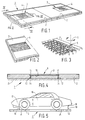
- FIG. 1 shows an embodiment of a parking plate according to the invention, which is provided with two flat, mirror-symmetrically disposed identical concrete plates 2, which are each provided with a device 3 for catching leakage liquids according to the invention.
- the position of the devices 3 with respect to the parking plate has been selected such that the devices 3 are located at those places where a vehicle parked on the parking plate 1 is expected to leak harmful liquids, such as oils and/or greases. Usually this will be near the exhaust and near the engine of the vehicle.
- Each device 3 is provided with a metal grid 4, which is disposed in a lowered portion of the plate 2, in such a manner that a substantially flat appearance of the plate is retained.
- the grid 4 closes a trough containing a water-repellent, leakage liquid-absorbing material. This will be explained in more detail hereafter.
- Figure 2 is a clear view of the grid 4 of the device 3 shown in Figure 1.
- Figure 3 shows a lock means 5 provided in the concrete plate 2, with which the grid 4 can be locked to the concrete plate in order to prevent the grid 4 and/or the absorbent material from being undesirably removed.
- the lock means 5 comprises a pin 6, which is capable of sliding movement within a slot provided in the grid 4. Rotation of the lock means 5 in the direction of the arrow 8 will cause the pin 6 to move out of the slot 7, after which the grid 4 can be removed so as to replace the absorbent material.
- FIG 4 is a cross-sectional view along the line IV-IV in Figure 1, wherein the grid 4 has been left out for easy reference.
- the parking plate 1 comprises the concrete plate 2 and a trough 9 of plastic material, which is positioned in a lowered portion of the concrete plate 2.
- the thin-walled plastic trough 9 is provided with a bottom plate 10, which slopes down from the centre towards the sides of the trough 9, as a result of which leakage liquids falling into the trough will flow to the sides of the trough.
- the bottom plate 10 of the trough 9 is provided with water discharge channels 11, which are connected to discharge channels 12 in the concrete plate 2. Liquid can only leave the trough via the discharge channels 11, 12.
- a cloth 13 of a water-repellent, leakage liquid-absorbing material is located inside the trough 9, and a powdered absorbent material is located within the discharge channels 11, 12.
- Leakage liquids from a parked vehicle fall through the grid 4 on to the absorbent cloth 13.
- Water is repelled by the cloth 13 and separated from the harmful oily and greasy constituents of the leakage liquids. Then the water flows to the discharge channels 11, 12 under the influence of gravity, where it disappears through the powdered or granular absorbent material 14 into the ground 15.
- the powdered or granular material 14 provides an extra filtration of the water already purified by the cloth 13, as a result of which any residual harmful liquids are removed as yet.
- the cloth 13 may be made of an absorbent material, such as OIL-DRI-MARINE (trademark), which is supplied by Anlag International B.V. of Lunteren.
- the powder 14 may be OIL-DRI (trademark) CHEM-SORB powder, for example, which is supplied by the same company.
- This OIL-DRI (trademark) absorbent material comprises polypropylene. the absorbent materials referred to above are also supplied by Bosco B.V. of Sneek under other brand names.
- Figure 5 is a side view of a car 16, which is parked on a parking plate 1 according to the invention.
- the car 16 comprises an engine 17 and an exhaust 18, from which harmful liquids 19 may leak.
- the liquids 19 are caught by the devices 3 positioned under the engine 17 and the exhaust 18.
- FIG. 6 is a cut-away view of a device 3 according to the invention.
- the trough 9 is made of liquid-tight concrete, whereby the bottom 10 of the trough 9 slopes down towards the edges. Near the edges, which are reinforced by means of metal sections 20, elongated discharge channels 12 are provided in the concrete plate 9.
- the metal sections 20 are provided with corresponding discharge channels 11.
- Absorbent cloths 13 are provided in the trough 9 and in the discharge channels 12, after which the trough 9 is closed by means of the grid 4.
- the leakage liquids flow in the direction of the arrow 23 through the grid 4 and the cloths 13 to the discharge channels 12, where the liquids purified by the absorbent cloths 13 disappear into the ground 15 located under the trough 9.
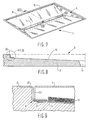
- Figures 7 - 9 show another embodiment of a device 3 according to the invention, wherein the trough 9 made of metal plates is provided with a water discharge channel 11 located in the centre of the trough 9, which is positioned lower than the edges of the trough 9.
- Figure 8 is a cross-sectional view of the device 3, along the line VIII-VIII in Figure 7, in which the bottom plate 10 sloping down from the edges towards the centre can be clearly distinguished.
- the edges of the trough 9 are made up of metal sections 20, which are positioned on edges of the concrete plate 2.
- Figure 9 shows a detail IX of the cross-section shown in Figure 7.
- the trough 9 comprises a metal bottom plate 10 sloping down towards the centre, metal sections 20 and metal flanges 21, by means of which the bottom plate 10 and the sections are interconnected.
- a leakage liquid-absorbing cloth 13, which catches liquids leaking through the grid 4, is present on the bottom plate 10.
- the grid 4 is kept spaced from the cloth 13 by means of bent-over edges 22.
- FIGS 10 and 11 show another embodiment of a parking plate 1 and a trough 9 respectively for a such a parking plate 1.
- the parking plate 1 is provided with a metal trough 9, which is mounted in a concrete plate 2.
- the trough 9 is provided with four parallel gutters 25, which are separated from each other by upright edges 26.
- the upper sides 27 of the edges 26 extend parallel to an edge 28 of the trough 9.
- Each gutter 25 comprises two bottom surfaces 29 sloping upwards from the edges 28 to the centre of the gutter 25.
- Each gutter 25 is in its centre provided with a water discharge channel 11, which, as a result the bottom surfaces 29 sloping upwards towards the centre, is located at the highest point of the gutter 25.
- Absorbent cloths 13 are positioned in the four gutters 25, said cloths at least abutting against edges 30 of the discharge channels 11.
- the trough 9 is furthermore provided with an angle section 31, a supporting structure 32 positioned therein and a cover grid 4 positioned thereon.
- the leakage liquids are caught by the absorbent cloths 13 and the purified water flows through the cloths 13 into the gutters 25. If the water should nevertheless contain any residual leakage liquids, the residual leakage liquids are caught via the bottom sides of the cloths 13 directed towards the gutters 25, since the water inside the gutters 25 will rise until the water level has reached the level of the discharge channel 11.
- the leakage liquids floating on the water are thereby pressed against the bottom sides of the cloths 13 and absorbed by the cloths as yet.
- the parking plate 1 is dimensioned 5 x 2.5 m, for example, with a thickness of 15 cm.
- the size of the grid will for example be 1 x 1.25 m. When the parking plate is used for lorries or buses, the dimensions will have to be larger.
- the grid 4 may be made of metal or plastic material.
- the grid has a porosity of 20%, for example, and apertures of 6 x 20 mm.
- the absorbent material may for example be made of polypropylene, sheepskin or other water-repellent materials.
- the device according to the invention is also suitable for catching leakage liquids from machines.
Landscapes
- Health & Medical Sciences (AREA)
- Life Sciences & Earth Sciences (AREA)
- Engineering & Computer Science (AREA)
- Hydrology & Water Resources (AREA)
- Public Health (AREA)
- Water Supply & Treatment (AREA)
- Examining Or Testing Airtightness (AREA)
- Water Treatment By Sorption (AREA)
- Lining And Supports For Tunnels (AREA)
- Electrical Discharge Machining, Electrochemical Machining, And Combined Machining (AREA)
Claims (11)
- Vorrichtung (3) zum Auffangen von Leckflüssigkeiten, die mit einem Trog (9) und einem Gitter (4) versehen ist, das mit dem Trog lösbar verbunden ist, wodurch der Trog verschlossen werden kann, dadurch gekennzeichnet, dass die Vorrichtung (3) außerdem mit einem wasserabstoßenden, Nichtwasserleckageflüssigkeitsabsorptionsmaterial (13) versehen ist, das zwischen dem Gitter (4) und dem Trog (9) angeordnet ist.
- Vorrichtung (3) nach Anspruch 1, dadurch gekennzeichnet, dass das Absorptionsmaterial (13) in dem Trog in Form eines Tuchs (13) vorhanden ist.
- Vorrichtung (3) nach Anspruch 1 oder 2, dadurch gekennzeichnet, dass der Trog (9) mit einem Boden versehen ist, der zumindest einen Wasseraustragkanal (11, 12) aufweist.
- Vorrichtung (3) nach Anspruch 3, dadurch gekennzeichnet, dass der Wasseraustragkanal (11, 12) in einem relativ erhöhten Teil des Bodens zu liegen kommt.
- Vorrichtung (3) nach Anspruch 3, dadurch gekennzeichnet, dass der Wasseraustragkanal (11, 12) in einem relativ niedrigen Teil des Bodens zu liegen kommt.
- Vorrichtung (3) nach Anspruch 4 oder 5, dadurch gekennzeichnet, dass der Wasseraustragkanal (11, 12) im Zentrum des Trogs (9) zu liegen kommt.
- Vorrichtung (3) nach Anspruch 3, 4 oder 5, dadurch gekennzeichnet, dass die Wasseraustragkanäle (11, 12) auf jeder Seite des Trogs (9) zu liegen kommen.
- Vorrichtung (3) nach einem der Ansprüche 3 bis 7, dadurch gekennzeichnet, dass der Wasseraustragkanal (11, 12) mit einem pulverisierten oder gekörnten Absorptionsmaterial versehen ist.
- Vorrichtung (3) nach einem der vorangehenden Ansprüche, dadurch gekennzeichnet, dass das Gitter (4) an dem Trog (9) verriegelt werden kann.
- Parkplatte für ein Fahrzeug, dadurch gekennzeichnet, dass die Parkplatte mit zumindest einer Vorrichtung (3) nach einem der vorangehenden Ansprüche versehen ist.
- Parkplatte nach Anspruch 10, dadurch gekennzeichnet, dass der Parkraum mit zumindest einer Platte versehen ist, die das zu parkende Fahrzeug trägt, wobei die Platte die Vorrichtung (3) zum Auffangen von Leckageflüssigkeiten aufweist.
Applications Claiming Priority (2)
| Application Number | Priority Date | Filing Date | Title |
|---|---|---|---|
| NL9400501 | 1994-03-30 | ||
| NL9400501A NL9400501A (nl) | 1994-03-30 | 1994-03-30 | Inrichting voor het opvangen van lekvloeistoffen, parkeerplaat voor een voertuig voorzien van een dergelijke inrichting alsmede bak en rooster geschikt voor een dergelijke inrichting. |
Publications (2)
| Publication Number | Publication Date |
|---|---|
| EP0675229A1 EP0675229A1 (de) | 1995-10-04 |
| EP0675229B1 true EP0675229B1 (de) | 2002-03-13 |
Family
ID=19864007
Family Applications (1)
| Application Number | Title | Priority Date | Filing Date |
|---|---|---|---|
| EP95200759A Expired - Lifetime EP0675229B1 (de) | 1994-03-30 | 1995-03-27 | Eine Vorrichtung für das Auffangen von Leckflüssigkeiten |
Country Status (5)
| Country | Link |
|---|---|
| EP (1) | EP0675229B1 (de) |
| AT (1) | ATE214446T1 (de) |
| DE (1) | DE69525783T2 (de) |
| DK (1) | DK0675229T3 (de) |
| NL (1) | NL9400501A (de) |
Families Citing this family (2)
| Publication number | Priority date | Publication date | Assignee | Title |
|---|---|---|---|---|
| DE102004024039A1 (de) * | 2004-05-07 | 2005-12-08 | Joachim Kulhanek | Vorrichtung zum wasserdurchlässigen Auffangen von Schadstoffen auf KFZ-Abstellplätzen |
| DE102006013095A1 (de) * | 2006-03-20 | 2007-10-04 | Jan Cornelis | Parkplatz |
Family Cites Families (2)
| Publication number | Priority date | Publication date | Assignee | Title |
|---|---|---|---|---|
| FR2659096B1 (fr) * | 1990-03-02 | 1992-07-10 | Pont A Mousson | Grille de caniveau pour chaussee revetue d'un enrobe drainant. |
| DE4010036C2 (de) * | 1990-03-29 | 2001-11-08 | Hansjuergen Grupp | Betonplatte zur Befestigung begrünter, befahr- oder begehbarer Flächen |
-
1994
- 1994-03-30 NL NL9400501A patent/NL9400501A/nl not_active Application Discontinuation
-
1995
- 1995-03-27 DK DK95200759T patent/DK0675229T3/da active
- 1995-03-27 EP EP95200759A patent/EP0675229B1/de not_active Expired - Lifetime
- 1995-03-27 DE DE69525783T patent/DE69525783T2/de not_active Expired - Fee Related
- 1995-03-27 AT AT95200759T patent/ATE214446T1/de not_active IP Right Cessation
Also Published As
| Publication number | Publication date |
|---|---|
| DE69525783T2 (de) | 2002-10-24 |
| NL9400501A (nl) | 1995-11-01 |
| ATE214446T1 (de) | 2002-03-15 |
| DE69525783D1 (de) | 2002-04-18 |
| DK0675229T3 (da) | 2002-05-27 |
| EP0675229A1 (de) | 1995-10-04 |
Similar Documents
| Publication | Publication Date | Title |
|---|---|---|
| US6287459B1 (en) | Drainwater treatment system for use in a vertical passageway | |
| US6190545B1 (en) | Drainwater treatment system for use in a horizontal passageway | |
| US7540295B2 (en) | Wash fluid containment system | |
| CA2400505C (en) | Filtration of hydrocarbon containing liquid | |
| US7291262B2 (en) | Road surface waste water treatment device and tubular water treatment unit | |
| US6524473B2 (en) | Gravitational separator and drainwater treatment system for use in a horizontal passageway | |
| US6648008B1 (en) | Method and apparatus for wash water containment and disposal | |
| US6200484B1 (en) | Surface water filtration apparatus | |
| US7799235B2 (en) | Fluid filter system and related method | |
| US5004534A (en) | Catch basin | |
| US20030121848A1 (en) | Water pollution trap with oil segregator/collector | |
| US10174493B2 (en) | Waste and/or hazardous liquid containment and collection system | |
| US10640398B2 (en) | Waste and/or hazardous liquid containment and collection system | |
| CA2606648A1 (en) | Storm drain filter | |
| CA2217629C (en) | Compact spill containment pan | |
| US7128831B2 (en) | Pollutant containment system | |
| KR101501925B1 (ko) | 비점오염을 정화하는 기능을 갖는 우수받이 | |
| KR100824268B1 (ko) | 배수처리장치 | |
| EP0675229A1 (de) | Eine Vorrichtung für das Auffangen von Leckflüssigkeiten | |
| US9630860B2 (en) | Waste and/or hazardous liquid containment and collection system | |
| DE4033112A1 (de) | Oel- und benzinabscheideanlage | |
| EP0762044A1 (de) | Bodenschutzsystem | |
| CA2143984C (en) | Filter system | |
| US5624205A (en) | Landfill water treatment system | |
| AU702264B3 (en) | A station for washing objects, particularly vehicles |
Legal Events
| Date | Code | Title | Description |
|---|---|---|---|
| PUAI | Public reference made under article 153(3) epc to a published international application that has entered the european phase |
Free format text: ORIGINAL CODE: 0009012 |
|
| AK | Designated contracting states |
Kind code of ref document: A1 Designated state(s): AT BE CH DE DK ES FR GB GR IE IT LI LU MC NL PT SE |
|
| RAX | Requested extension states of the european patent have changed |
Free format text: LT PAYMENT 950327;SI PAYMENT 950327 |
|
| RAP1 | Party data changed (applicant data changed or rights of an application transferred) |
Owner name: DEN BOER BETON NIEUW-LEKKERLAND B.V. |
|
| RIN1 | Information on inventor provided before grant (corrected) |
Inventor name: VAN SCHAIJK, PETRUS ADRIANUS |
|
| 17P | Request for examination filed |
Effective date: 19960403 |
|
| 17Q | First examination report despatched |
Effective date: 19991022 |
|
| GRAG | Despatch of communication of intention to grant |
Free format text: ORIGINAL CODE: EPIDOS AGRA |
|
| RIN1 | Information on inventor provided before grant (corrected) |
Inventor name: VAN SCHAIJK, PETRUS ADRIANUS |
|
| GRAG | Despatch of communication of intention to grant |
Free format text: ORIGINAL CODE: EPIDOS AGRA |
|
| GRAH | Despatch of communication of intention to grant a patent |
Free format text: ORIGINAL CODE: EPIDOS IGRA |
|
| GRAH | Despatch of communication of intention to grant a patent |
Free format text: ORIGINAL CODE: EPIDOS IGRA |
|
| REG | Reference to a national code |
Ref country code: GB Ref legal event code: IF02 |
|
| GRAA | (expected) grant |
Free format text: ORIGINAL CODE: 0009210 |
|
| AK | Designated contracting states |
Kind code of ref document: B1 Designated state(s): AT BE CH DE DK ES FR GB GR IE IT LI LU MC NL PT SE |
|
| AX | Request for extension of the european patent |
Free format text: LT PAYMENT 19950327;SI PAYMENT 19950327 |
|
| LTIE | Lt: invalidation of european patent or patent extension | ||
| PG25 | Lapsed in a contracting state [announced via postgrant information from national office to epo] |
Ref country code: LI Free format text: LAPSE BECAUSE OF FAILURE TO SUBMIT A TRANSLATION OF THE DESCRIPTION OR TO PAY THE FEE WITHIN THE PRESCRIBED TIME-LIMIT Effective date: 20020313 Ref country code: IT Free format text: LAPSE BECAUSE OF FAILURE TO SUBMIT A TRANSLATION OF THE DESCRIPTION OR TO PAY THE FEE WITHIN THE PRE;WARNING: LAPSES OF ITALIAN PATENTS WITH EFFECTIVE DATE BEFORE 2007 MAY HAVE OCCURRED AT ANY TIME BEFORE 2007. THE CORRECT EFFECTIVE DATE MAY BE DIFFERENT FROM THE ONE RECORDED.SCRIBED TIME-LIMIT Effective date: 20020313 Ref country code: GR Free format text: LAPSE BECAUSE OF FAILURE TO SUBMIT A TRANSLATION OF THE DESCRIPTION OR TO PAY THE FEE WITHIN THE PRESCRIBED TIME-LIMIT Effective date: 20020313 Ref country code: FR Free format text: LAPSE BECAUSE OF FAILURE TO SUBMIT A TRANSLATION OF THE DESCRIPTION OR TO PAY THE FEE WITHIN THE PRESCRIBED TIME-LIMIT Effective date: 20020313 Ref country code: CH Free format text: LAPSE BECAUSE OF FAILURE TO SUBMIT A TRANSLATION OF THE DESCRIPTION OR TO PAY THE FEE WITHIN THE PRESCRIBED TIME-LIMIT Effective date: 20020313 Ref country code: AT Free format text: LAPSE BECAUSE OF FAILURE TO SUBMIT A TRANSLATION OF THE DESCRIPTION OR TO PAY THE FEE WITHIN THE PRESCRIBED TIME-LIMIT Effective date: 20020313 |
|
| REF | Corresponds to: |
Ref document number: 214446 Country of ref document: AT Date of ref document: 20020315 Kind code of ref document: T |
|
| REG | Reference to a national code |
Ref country code: CH Ref legal event code: EP |
|
| PG25 | Lapsed in a contracting state [announced via postgrant information from national office to epo] |
Ref country code: MC Free format text: LAPSE BECAUSE OF NON-PAYMENT OF DUE FEES Effective date: 20020327 Ref country code: IE Free format text: LAPSE BECAUSE OF NON-PAYMENT OF DUE FEES Effective date: 20020327 |
|
| PGFP | Annual fee paid to national office [announced via postgrant information from national office to epo] |
Ref country code: LU Payment date: 20020405 Year of fee payment: 8 |
|
| PGFP | Annual fee paid to national office [announced via postgrant information from national office to epo] |
Ref country code: BE Payment date: 20020416 Year of fee payment: 8 |
|
| PGFP | Annual fee paid to national office [announced via postgrant information from national office to epo] |
Ref country code: SE Payment date: 20020417 Year of fee payment: 8 |
|
| REF | Corresponds to: |
Ref document number: 69525783 Country of ref document: DE Date of ref document: 20020418 |
|
| REG | Reference to a national code |
Ref country code: DK Ref legal event code: T3 |
|
| PG25 | Lapsed in a contracting state [announced via postgrant information from national office to epo] |
Ref country code: GB Free format text: LAPSE BECAUSE OF NON-PAYMENT OF DUE FEES Effective date: 20020613 |
|
| PG25 | Lapsed in a contracting state [announced via postgrant information from national office to epo] |
Ref country code: PT Free format text: LAPSE BECAUSE OF FAILURE TO SUBMIT A TRANSLATION OF THE DESCRIPTION OR TO PAY THE FEE WITHIN THE PRESCRIBED TIME-LIMIT Effective date: 20020614 |
|
| REG | Reference to a national code |
Ref country code: CH Ref legal event code: PL |
|
| PG25 | Lapsed in a contracting state [announced via postgrant information from national office to epo] |
Ref country code: ES Free format text: LAPSE BECAUSE OF FAILURE TO SUBMIT A TRANSLATION OF THE DESCRIPTION OR TO PAY THE FEE WITHIN THE PRESCRIBED TIME-LIMIT Effective date: 20020925 |
|
| EN | Fr: translation not filed | ||
| REG | Reference to a national code |
Ref country code: IE Ref legal event code: MM4A |
|
| PLBE | No opposition filed within time limit |
Free format text: ORIGINAL CODE: 0009261 |
|
| STAA | Information on the status of an ep patent application or granted ep patent |
Free format text: STATUS: NO OPPOSITION FILED WITHIN TIME LIMIT |
|
| GBPC | Gb: european patent ceased through non-payment of renewal fee |
Effective date: 20020613 |
|
| 26N | No opposition filed |
Effective date: 20021216 |
|
| PG25 | Lapsed in a contracting state [announced via postgrant information from national office to epo] |
Ref country code: LU Free format text: LAPSE BECAUSE OF NON-PAYMENT OF DUE FEES Effective date: 20030327 |
|
| PG25 | Lapsed in a contracting state [announced via postgrant information from national office to epo] |
Ref country code: SE Free format text: LAPSE BECAUSE OF NON-PAYMENT OF DUE FEES Effective date: 20030328 |
|
| PG25 | Lapsed in a contracting state [announced via postgrant information from national office to epo] |
Ref country code: BE Free format text: LAPSE BECAUSE OF NON-PAYMENT OF DUE FEES Effective date: 20030331 |
|
| BERE | Be: lapsed |
Owner name: *DEN BOER BETON NIEUW-LEKKERLAND B.V. Effective date: 20030331 |
|
| EUG | Se: european patent has lapsed | ||
| PGFP | Annual fee paid to national office [announced via postgrant information from national office to epo] |
Ref country code: DK Payment date: 20040930 Year of fee payment: 10 |
|
| PG25 | Lapsed in a contracting state [announced via postgrant information from national office to epo] |
Ref country code: DK Free format text: LAPSE BECAUSE OF NON-PAYMENT OF DUE FEES Effective date: 20050331 |
|
| REG | Reference to a national code |
Ref country code: DK Ref legal event code: EBP |
|
| PGFP | Annual fee paid to national office [announced via postgrant information from national office to epo] |
Ref country code: DE Payment date: 20060927 Year of fee payment: 12 |
|
| PGFP | Annual fee paid to national office [announced via postgrant information from national office to epo] |
Ref country code: NL Payment date: 20060930 Year of fee payment: 12 |
|
| NLV4 | Nl: lapsed or anulled due to non-payment of the annual fee |
Effective date: 20071001 |
|
| PG25 | Lapsed in a contracting state [announced via postgrant information from national office to epo] |
Ref country code: NL Free format text: LAPSE BECAUSE OF NON-PAYMENT OF DUE FEES Effective date: 20071001 Ref country code: DE Free format text: LAPSE BECAUSE OF NON-PAYMENT OF DUE FEES Effective date: 20071002 |