EP0675256A1 - Dispositif pour tenir une porte ouverte ayant un déclencheur manuel ou automatique - Google Patents
Dispositif pour tenir une porte ouverte ayant un déclencheur manuel ou automatique Download PDFInfo
- Publication number
- EP0675256A1 EP0675256A1 EP95302186A EP95302186A EP0675256A1 EP 0675256 A1 EP0675256 A1 EP 0675256A1 EP 95302186 A EP95302186 A EP 95302186A EP 95302186 A EP95302186 A EP 95302186A EP 0675256 A1 EP0675256 A1 EP 0675256A1
- Authority
- EP
- European Patent Office
- Prior art keywords
- door
- roller assembly
- door catch
- housing
- power
- Prior art date
- Legal status (The legal status is an assumption and is not a legal conclusion. Google has not performed a legal analysis and makes no representation as to the accuracy of the status listed.)
- Withdrawn
Links
- 238000009434 installation Methods 0.000 description 3
- 230000000694 effects Effects 0.000 description 2
- 230000032683 aging Effects 0.000 description 1
- 230000006835 compression Effects 0.000 description 1
- 238000007906 compression Methods 0.000 description 1
- 230000003247 decreasing effect Effects 0.000 description 1
- 230000001771 impaired effect Effects 0.000 description 1
- 238000007689 inspection Methods 0.000 description 1
- 238000012423 maintenance Methods 0.000 description 1
- 238000004519 manufacturing process Methods 0.000 description 1
- 239000000779 smoke Substances 0.000 description 1
Images
Classifications
-
- E—FIXED CONSTRUCTIONS
- E05—LOCKS; KEYS; WINDOW OR DOOR FITTINGS; SAFES
- E05F—DEVICES FOR MOVING WINGS INTO OPEN OR CLOSED POSITION; CHECKS FOR WINGS; WING FITTINGS NOT OTHERWISE PROVIDED FOR, CONCERNED WITH THE FUNCTIONING OF THE WING
- E05F3/00—Closers or openers with braking devices, e.g. checks; Construction of pneumatic or liquid braking devices
- E05F3/22—Additional arrangements for closers, e.g. for holding the wing in opened or other position
- E05F3/221—Mechanical power-locks, e.g. for holding the wing open or for free-moving zones
- E05F3/222—Mechanical power-locks, e.g. for holding the wing open or for free-moving zones electrically operated
-
- E—FIXED CONSTRUCTIONS
- E05—LOCKS; KEYS; WINDOW OR DOOR FITTINGS; SAFES
- E05F—DEVICES FOR MOVING WINGS INTO OPEN OR CLOSED POSITION; CHECKS FOR WINGS; WING FITTINGS NOT OTHERWISE PROVIDED FOR, CONCERNED WITH THE FUNCTIONING OF THE WING
- E05F3/00—Closers or openers with braking devices, e.g. checks; Construction of pneumatic or liquid braking devices
- E05F3/22—Additional arrangements for closers, e.g. for holding the wing in opened or other position
- E05F2003/228—Arrangements where the end of the closer arm is sliding in a track
-
- E—FIXED CONSTRUCTIONS
- E05—LOCKS; KEYS; WINDOW OR DOOR FITTINGS; SAFES
- E05Y—INDEXING SCHEME ASSOCIATED WITH SUBCLASSES E05D AND E05F, RELATING TO CONSTRUCTION ELEMENTS, ELECTRIC CONTROL, POWER SUPPLY, POWER SIGNAL OR TRANSMISSION, USER INTERFACES, MOUNTING OR COUPLING, DETAILS, ACCESSORIES, AUXILIARY OPERATIONS NOT OTHERWISE PROVIDED FOR, APPLICATION THEREOF
- E05Y2900/00—Application of doors, windows, wings or fittings thereof
- E05Y2900/10—Application of doors, windows, wings or fittings thereof for buildings or parts thereof
- E05Y2900/13—Type of wing
- E05Y2900/132—Doors
Definitions
- This invention relates generally to a door hold-open device for use with a door closer and more particularly to a door hold-open device which is intended to release upon power failure or upon application of over-riding release force by manual means.
- Hold-open devices for doors are needed for many purposes. However, it is often also desirable to deactivate the hold-open device, so that the door may freely open and close without being held in a hold-open position. In case of fire, for example, it may be desirable to deactivate hold-open devices to prevent spread of the fire. During times of high traffic, in a school or theatre, it is necessary to provide a hold-open device for doors, while such may be undesirable at other times.
- Door closers having hold-open features are well known due to their convenience and efficiency in permitting high volume pedestrian traffic during peak traffic periods while providing safety and security at other times. It is sometimes necessary to have automatic release of the hold-open mechanism, particularly in the case of fire. Fusible links have been used for this purpose, but they require high temperature to release and, by then, it may be too late to contain the fire. Thus, it is preferred to use a smoke detector as a means for detecting fire or other dangerous condition and as a trigger for the automatic release of the hold-open mechanism.
- a door hold-open device having manual and automatic release capabilities, comprising a track having a substantially U-shaped cross-section and acting as a guide for a roller assembly, said roller assembly having means for engaging a door catch means and provision for attachment to a door control arm, and said door catch means being fixed within said track, characterised in that said door catch means further comprises a power-actuated plunger-driven means for engaging and for releasing said roller assembly and means for manually over-riding said power actuated plunger-driven means for engaging said roller assembly to release a door.
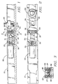
- FIGS 1 and 2 show elevation and plan views of the hold-open device together with an illustration of how it operates.
- the hold-open device consists, basically, of a substantially straight track 21, a roller assembly slide 29, and a door catch mechanism.
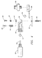
- Figure 4 shows an exploded view of the roller assembly slide 28 and 29 in a latched position relative to the door catch mechanism.
- the door catch assembly consists of a housing 24 which is mounted within track 21 by means of pivot pin 30 through a rearward end of housing 24.
- a longitudinal cavity in housing 24 is threaded at the rearward end of the housing to receive a power actuator 22 which may be either an electrical solenoid or an air cylinder.
- a plunger 23 Projecting from actuator 22 and into the longitudinal cavity of housing 24 is a plunger 23 which, in operation, is driven by actuator 22.
- the longitudinal cavity within housing 24 is diverted near a forward end of the housing to open onto the bottom surface of the "U" shaped channel forming track 21.
- a latch member consisting of retaining ball 31 and locking ball 32 is disposed within the cavity of housing 24.
- plunger 23 When plunger 23 is driven forward it drives retaining ball 31 forward also and forces locking ball 32 downward against the lower surface of track 21. If the door is open so that roller assembly 29 is moved to its leftward limit so that slide latch 28 is under housing 24 with latching or locking hole 35 aligned with the lateral exit of the housing cavity, locking ball 32 will act to hold the door open by preventing rightward movement of roller assembly 29.
- Adjustable bias force is provided through spring adjusting mounting screws 33, power springs 34, spring retaining nuts 25, and spring retainer clip 27.
- Spring adjusting mounting screws 33 extend upward through the bottom of track 21 and through loose holes in spring retainer clip 27.
- Power springs 34 sit atop spring retainer clip 27 surrounding spring adjusting mounting screws 33 and are held in place by spring retaining nuts 25.
- the hold-open device is activated by electric or pneumatic power applied to actuator 22. It automatically releases upon electrical failure or loss of air pressure. It also allows for manual override of the hold-open feature without interruption of the electric or pneumatic power.
- the door catch assembly is also designed to allow adjustment of hold-open force to require greater or lesser manual override effort for closing the door when actuator 22 is powered.
- the door catch mechanism is mounted in track 21 by means of pivot pin 30 and is biased in its operating position by means of spring adjusting mounting screws 33, spring retaining nuts 25, power springs 34, and spring retainer clip 27.
- actuator 22 When actuator 22 is energized by air or electric power, plunger 23 moves forward pushing retainer ball 31 against locking ball 32, thereby forcing locking ball 32 to press tightly against the bottom of track 21.
- roller assembly 29 and slide latch 28, to which roller assembly 29 is connected move leftward so that the beveled leading edge of slide latch 28 underrides housing 24 and forces locking ball 32 upward. This causes housing 24 to pivot around pivot pin 30 while slide latch 28 continues to move leftward until locking ball 32 is aligned with locking hole 35 of slide latch 28.
- the door catch mechanism then pivots back to its original position and captures slide latch 28 in the hold-open position.
- roller assembly 29 and slide latch 28 move in the rightward direction again causing the door catch mechanism to pivot to allow locking ball 32 to slip over the edge of hole 35 in slide latch 28.
- deenergizing actuator 22 by interrupting either the electrical or air supply.
- plunger 23 moves rearward to release retaining ball 31 and locking ball 32 so that slide latch 28 and roller assembly 29 move rightward without the necessity for pivoting of the door catch mechanism under the influence of the door closer.
- Power adjustment screw 26 can then be turned clockwise to lift spring retainer clip 27, thereby compressing power springs 34 and increasing downward pressure on power adjustment ledge 36 and thereby increasing hold-open force. By turning power adjustment screw 26 counterclockwise, the opposite effect is achieved and hold-open force is decreased. Screw retaining spring 37 prevents unintentional movement of power adjustment screw 26.
Landscapes
- Engineering & Computer Science (AREA)
- Mechanical Engineering (AREA)
- Power-Operated Mechanisms For Wings (AREA)
Applications Claiming Priority (2)
| Application Number | Priority Date | Filing Date | Title |
|---|---|---|---|
| US22132894A | 1994-03-31 | 1994-03-31 | |
| US221328 | 1994-03-31 |
Publications (1)
| Publication Number | Publication Date |
|---|---|
| EP0675256A1 true EP0675256A1 (fr) | 1995-10-04 |
Family
ID=22827359
Family Applications (1)
| Application Number | Title | Priority Date | Filing Date |
|---|---|---|---|
| EP95302186A Withdrawn EP0675256A1 (fr) | 1994-03-31 | 1995-03-31 | Dispositif pour tenir une porte ouverte ayant un déclencheur manuel ou automatique |
Country Status (2)
| Country | Link |
|---|---|
| EP (1) | EP0675256A1 (fr) |
| CA (1) | CA2145807A1 (fr) |
Cited By (3)
| Publication number | Priority date | Publication date | Assignee | Title |
|---|---|---|---|---|
| FR2752261A1 (fr) * | 1996-08-07 | 1998-02-13 | Gretsch Unitas Gmbh | Dispositif de blocage pour une porte |
| JP2012217734A (ja) * | 2011-04-12 | 2012-11-12 | Ryobi Ltd | 防火戸閉鎖装置 |
| EP3156574A1 (fr) * | 2015-10-15 | 2017-04-19 | Frinova GmbH | Systeme dote d'une porte coulissante et d'une partie fixe, sur laquelle la porte coulissante peut etre deplacee |
Citations (3)
| Publication number | Priority date | Publication date | Assignee | Title |
|---|---|---|---|---|
| DE2531314A1 (de) * | 1974-08-01 | 1976-02-19 | Rixson Firemark | Elektrische tuer-halte- und loesevorrichtung |
| DE2837943A1 (de) * | 1977-09-12 | 1979-03-22 | Mac Gregor International Sa | Tuerbetaetigungsvorrichtung |
| CH671802A5 (fr) * | 1986-11-05 | 1989-09-29 | Protor Ag |
-
1995
- 1995-03-29 CA CA002145807A patent/CA2145807A1/fr not_active Abandoned
- 1995-03-31 EP EP95302186A patent/EP0675256A1/fr not_active Withdrawn
Patent Citations (3)
| Publication number | Priority date | Publication date | Assignee | Title |
|---|---|---|---|---|
| DE2531314A1 (de) * | 1974-08-01 | 1976-02-19 | Rixson Firemark | Elektrische tuer-halte- und loesevorrichtung |
| DE2837943A1 (de) * | 1977-09-12 | 1979-03-22 | Mac Gregor International Sa | Tuerbetaetigungsvorrichtung |
| CH671802A5 (fr) * | 1986-11-05 | 1989-09-29 | Protor Ag |
Cited By (3)
| Publication number | Priority date | Publication date | Assignee | Title |
|---|---|---|---|---|
| FR2752261A1 (fr) * | 1996-08-07 | 1998-02-13 | Gretsch Unitas Gmbh | Dispositif de blocage pour une porte |
| JP2012217734A (ja) * | 2011-04-12 | 2012-11-12 | Ryobi Ltd | 防火戸閉鎖装置 |
| EP3156574A1 (fr) * | 2015-10-15 | 2017-04-19 | Frinova GmbH | Systeme dote d'une porte coulissante et d'une partie fixe, sur laquelle la porte coulissante peut etre deplacee |
Also Published As
| Publication number | Publication date |
|---|---|
| CA2145807A1 (fr) | 1995-10-01 |
Similar Documents
| Publication | Publication Date | Title |
|---|---|---|
| US5673514A (en) | Time delay release mechanism for a fire barrier | |
| US4050114A (en) | Door closer assembly | |
| US7299848B2 (en) | Closure member control systems, including door control systems for barrier housings, and associated methods | |
| US4161804A (en) | Heat-actuated door latch | |
| US5245879A (en) | Fail-safe fire door release mechanism having automatic reset | |
| CN212176889U (zh) | 一种防火门电动闭门器 | |
| US7755004B2 (en) | Motorized hinge system for oven door | |
| EP1126111B1 (fr) | Arrêt de porte détachable pour véhicule automobile | |
| US4005886A (en) | Flush bolt mechanisms | |
| US4106753A (en) | Automatic anti-fall device for power-driven lifting machinery | |
| DE19606204C1 (de) | Elektromechanische Feststellvorrichtung für Türflügel mit einem Türschließer | |
| US11851941B2 (en) | Hold-open arrester arrangement having a hold-open function to hold a door open | |
| US5484176A (en) | Latch mechanism | |
| CA2145807A1 (fr) | Dispositif de maintien de porte en position ouverte, avec commande automatique ou manuelle de fermeture | |
| EP3971378A1 (fr) | Système de bloc-porte pour maintenir en position ouverte ayant une fonction de maintien en position ouverte pour maintenir une porte ouverte | |
| EP0649961A1 (fr) | Arrêt pour porte | |
| EP0651848B1 (fr) | Dispositifs de fermeture de porte | |
| US6981538B2 (en) | Positional control device for sectional doors | |
| US5864986A (en) | Checking device for roller supported doors | |
| JP5580775B2 (ja) | 防火戸閉鎖装置 | |
| EP0789126B1 (fr) | Fenêtre avec une crémone et un dispositif de commande | |
| JPH0743213U (ja) | 扉開閉機構 | |
| GB2374118A (en) | Door Closing Mechanism | |
| CN210164375U (zh) | 一种防火闭窗器 | |
| JP4617057B2 (ja) | パーキングブレーキのケーブル引張り調節装置 |
Legal Events
| Date | Code | Title | Description |
|---|---|---|---|
| PUAI | Public reference made under article 153(3) epc to a published international application that has entered the european phase |
Free format text: ORIGINAL CODE: 0009012 |
|
| AK | Designated contracting states |
Kind code of ref document: A1 Designated state(s): DE FR GB IT |
|
| 17P | Request for examination filed |
Effective date: 19960319 |
|
| STAA | Information on the status of an ep patent application or granted ep patent |
Free format text: STATUS: THE APPLICATION HAS BEEN WITHDRAWN |
|
| 18W | Application withdrawn |
Withdrawal date: 19970523 |