EP0675285A1 - Profil de pale d'éolienne - Google Patents
Profil de pale d'éolienne Download PDFInfo
- Publication number
- EP0675285A1 EP0675285A1 EP95103694A EP95103694A EP0675285A1 EP 0675285 A1 EP0675285 A1 EP 0675285A1 EP 95103694 A EP95103694 A EP 95103694A EP 95103694 A EP95103694 A EP 95103694A EP 0675285 A1 EP0675285 A1 EP 0675285A1
- Authority
- EP
- European Patent Office
- Prior art keywords
- airfoil
- blade
- region
- chord line
- maximum lift
- Prior art date
- Legal status (The legal status is an assumption and is not a legal conclusion. Google has not performed a legal analysis and makes no representation as to the accuracy of the status listed.)
- Granted
Links
- 230000000694 effects Effects 0.000 claims abstract description 23
- 238000004140 cleaning Methods 0.000 description 7
- 241000238631 Hexapoda Species 0.000 description 5
- 238000009825 accumulation Methods 0.000 description 4
- 239000000356 contaminant Substances 0.000 description 4
- 230000007246 mechanism Effects 0.000 description 4
- 230000035945 sensitivity Effects 0.000 description 3
- 238000004519 manufacturing process Methods 0.000 description 2
- 238000000034 method Methods 0.000 description 2
- 230000001105 regulatory effect Effects 0.000 description 2
- 238000007493 shaping process Methods 0.000 description 2
- 238000007792 addition Methods 0.000 description 1
- 230000008859 change Effects 0.000 description 1
- 239000002131 composite material Substances 0.000 description 1
- 238000010276 construction Methods 0.000 description 1
- 238000011109 contamination Methods 0.000 description 1
- 239000003344 environmental pollutant Substances 0.000 description 1
- 230000003628 erosive effect Effects 0.000 description 1
- 239000011152 fibreglass Substances 0.000 description 1
- 231100000719 pollutant Toxicity 0.000 description 1
- 230000008569 process Effects 0.000 description 1
- 238000000926 separation method Methods 0.000 description 1
- 230000007704 transition Effects 0.000 description 1
- 239000002023 wood Substances 0.000 description 1
Images


Classifications
-
- F—MECHANICAL ENGINEERING; LIGHTING; HEATING; WEAPONS; BLASTING
- F03—MACHINES OR ENGINES FOR LIQUIDS; WIND, SPRING, OR WEIGHT MOTORS; PRODUCING MECHANICAL POWER OR A REACTIVE PROPULSIVE THRUST, NOT OTHERWISE PROVIDED FOR
- F03D—WIND MOTORS
- F03D1/00—Wind motors with rotation axis substantially parallel to the air flow entering the rotor
- F03D1/06—Rotors
- F03D1/0608—Rotors characterised by their aerodynamic shape
- F03D1/0633—Rotors characterised by their aerodynamic shape of the blades
- F03D1/0641—Rotors characterised by their aerodynamic shape of the blades of the section profile of the blades, i.e. aerofoil profile
-
- F—MECHANICAL ENGINEERING; LIGHTING; HEATING; WEAPONS; BLASTING
- F05—INDEXING SCHEMES RELATING TO ENGINES OR PUMPS IN VARIOUS SUBCLASSES OF CLASSES F01-F04
- F05B—INDEXING SCHEME RELATING TO WIND, SPRING, WEIGHT, INERTIA OR LIKE MOTORS, TO MACHINES OR ENGINES FOR LIQUIDS COVERED BY SUBCLASSES F03B, F03D AND F03G
- F05B2270/00—Control
- F05B2270/10—Purpose of the control system
- F05B2270/1016—Purpose of the control system in variable speed operation
-
- Y—GENERAL TAGGING OF NEW TECHNOLOGICAL DEVELOPMENTS; GENERAL TAGGING OF CROSS-SECTIONAL TECHNOLOGIES SPANNING OVER SEVERAL SECTIONS OF THE IPC; TECHNICAL SUBJECTS COVERED BY FORMER USPC CROSS-REFERENCE ART COLLECTIONS [XRACs] AND DIGESTS
- Y02—TECHNOLOGIES OR APPLICATIONS FOR MITIGATION OR ADAPTATION AGAINST CLIMATE CHANGE
- Y02E—REDUCTION OF GREENHOUSE GAS [GHG] EMISSIONS, RELATED TO ENERGY GENERATION, TRANSMISSION OR DISTRIBUTION
- Y02E10/00—Energy generation through renewable energy sources
- Y02E10/70—Wind energy
- Y02E10/72—Wind turbines with rotation axis in wind direction
-
- Y—GENERAL TAGGING OF NEW TECHNOLOGICAL DEVELOPMENTS; GENERAL TAGGING OF CROSS-SECTIONAL TECHNOLOGIES SPANNING OVER SEVERAL SECTIONS OF THE IPC; TECHNICAL SUBJECTS COVERED BY FORMER USPC CROSS-REFERENCE ART COLLECTIONS [XRACs] AND DIGESTS
- Y10—TECHNICAL SUBJECTS COVERED BY FORMER USPC
- Y10S—TECHNICAL SUBJECTS COVERED BY FORMER USPC CROSS-REFERENCE ART COLLECTIONS [XRACs] AND DIGESTS
- Y10S416/00—Fluid reaction surfaces, i.e. impellers
- Y10S416/02—Formulas of curves
-
- Y—GENERAL TAGGING OF NEW TECHNOLOGICAL DEVELOPMENTS; GENERAL TAGGING OF CROSS-SECTIONAL TECHNOLOGIES SPANNING OVER SEVERAL SECTIONS OF THE IPC; TECHNICAL SUBJECTS COVERED BY FORMER USPC CROSS-REFERENCE ART COLLECTIONS [XRACs] AND DIGESTS
- Y10—TECHNICAL SUBJECTS COVERED BY FORMER USPC
- Y10S—TECHNICAL SUBJECTS COVERED BY FORMER USPC CROSS-REFERENCE ART COLLECTIONS [XRACs] AND DIGESTS
- Y10S416/00—Fluid reaction surfaces, i.e. impellers
- Y10S416/05—Variable camber or chord length
Definitions
- This invention relates to the field of wind turbines and specifically to a family of airfoils for use in the blade of such a turbine.
- the instant invention is concerned with an improved family of airfoils for the blade of a horizontal-axis wind turbine, wherein the airfoil's maximum lift coefficient is designed to be largely insensitive to leading edge roughness.
- U. S. Patent No. 4,606,519 to Fertis et al. is directed to an airfoil having an offset in the upper surface.
- the airfoil is so designed to improve the lift and stall characteristics of the wing at high, cruising airspeeds, without substantially increasing the drag. Minimizing roughness sensitivity is not a concern of the patent.
- the instant invention in contrast, contemplates a smooth suction surface without the discrete step or offset feature of the patent.
- Laminar flow over an airfoil is the concern of U. S. Patent No. 4,619,423 to Holmes et al.
- the patent is concerned with shaping the interface mechanism at the juncture of the leading edge structure with both the upper and lower main wing skin panels, to allow laminar flow to occur over both the upper and lower surfaces of the airfoil.
- the patent uses passive geometric interface devices to help maintain laminar flow over a discontinuity in the airfoil surface.
- maintaining laminar flow by shaping an interface mechanism is not a concern nor a design requirement for the airfoils of the instant invention.
- the airfoil of U. S. Patent No. 4,830,315 to Presz, Jr. has a relatively thin trailing edge with a series of troughs and ridges to form wave-like surface undulations.
- the patent to Presy, Jr. et al. is not concerned with roughness created by insects and airborne contaminants. It is further noted that roughness is generally more pronounced on the leading edge of the airfoil, whereas the patent is concerned with trailing edge geometry to delay boundary layer separation without creating a noticeable drag penalty.
- a non-smooth surface shape is disclosed in U. S. Patent No. 5,114,099 to Gao.
- the surface of the instant invention is of the conventional, generally smooth, type.
- the surface shape of the patent attempts to reduce drag. Roughness and its effects are not the concern of the patent.
- the primary goal of new wind turbine blade designs is to convert the kinetic energy in the wind into mechanical energy as inexpensively and efficiently as possible. Any disruptions in the efficient operations of a wind turbine affect the total energy output. Thus, early generator replacement from excessive peak power and cleaning the large-sized wind turbine blades can be expensive to perform.
- the blades of horizontal-axis wind turbines typically become coated with insect accumulation and airborne contaminants. This collection of dirt, called roughness, predominantly happens at the leading edge of the blade. The roughness can interrupt the efficient operation of the blades, and diminish their overall energy output.
- the instant invention is directed to several families of airfoils for the blades of a wind turbine, and the airfoils are designed to have a maximum lift coefficient that is less sensitive to roughness effects.
- the blades range in length from 1 - 25 meters.
- the airfoils range from 16% (tip region) - 24% (root region) thickness, with thickness being defined by the airfoil depth perpendicular to the chord line divided by the cord line length, and are used in a blade having a length from 1 to 25 meters.
- the airfoils are designed with a Reynolds number in the range from 400,000 (root region) to 4,000,000 (outboard region), with a maximum lift coefficient of 1.0 (tip region) to 1.7 (root region).
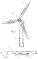
- Figure 1 is a perspective of a horizontal axis wind turbine that can incorporate the instant invention.
- Figure 2 is a perspective of a blade that incorporates the airfoils of the instant invention.
- Figure 3 is a profile of a first family airfoil for the tip region of a blade 15 to 25 meters in size, in accordance with the instant invention.
- Figure 4 is a profile of a first family airfoil for the outboard region of a blade 15 to 25 meters in size, in accordance with the instant invention.
- Figure 5 is a profile of a first family airfoil for the root region of a blade 15 to 25 meters in size, in accordance with the instant invention.
- Figure 6 is a profile of a second family airfoil for the tip region of a blade 5 to 10 meters in size, in accordance with the instant invention.
- Figure 7 is a profile of a second family airfoil for the outboard region of a blade 5 to 10 meters in size, in accordance with the instant invention.
- Figure 8 is a profile of a second family airfoil for the outboard region of a blade 5 to 10 meters in size in accordance with the instant invention.
- Figure 9 is a profile of a third family airfoil for the tip region of a blade 1 to 5 meters in size in accordance with the instant invention.
- Figure 10 is a profile of a third family airfoil for the root region of a blade 1 to 5 meters in size in accordance with the instant invention.
- Figure 1 shows a typical stall-regulated horizontal-axis wind turbine. Blades 5 rotate about center horizontal-axis shaft 4, having a center axis of rotation and the entire rotor mechanism is supported by support tower 3.
- the instant invention is particularly concerned with blades for such a wind turbine.
- a perspective of the blade is shown in Figure 2.
- the blades are typically made of either fiberglass or wood composite.
- the blades containing the airfoils of the subject invention range in size from 1 to 25 meters to form a rotor which can be as large as 50 meters in diameter.
- Blades typically have performance characteristics that are tailored to change from the blade tip 8, (80% - 100% radius from the center of rotation) to the blade outboard region 7, (50% - 80% from the center of rotation), to the root region 6 (up to 50% radius from the center of rotation). Effectively the root region is considered to be the region from 20% to 50% from the center of rotation.
- the airfoil in the tip region of the blade must have a maximum lift coefficient that is 25% to 40% lower than typical aircraft airfoils.
- an airfoil in the root region of the blade must have a high maximum lift coefficient to aid rotor start-up and energy production at medium wind speeds.
- the airfoil families of the instant invention are incorporated in a blade whose maximum lift coefficient increases in a continuous manner from blade tip to blade root for effective peak power control. This results in approximately a 15% - 30% greater swept disc area for a given generator size and results in increased energy production.
- All three airfoil families of the present invention are designed to have the maximum lift coefficient be less sensitive to roughness effects.
- the airfoil's shape is geometrically tailored to induce transition from laminar to turbulent flow near the leading edge of the airfoil as the maximum lift coefficient is approached.
- the first family of airfoils which are for a blade 15 to 25 meters in length are illustrated in Figures 3 through 5.
- Figure 3 is a profile of a tip airfoil 11 in accordance with the instant invention.
- the airfoil has specific geometric tailoring to achieve a maximum lift coefficient of 1.1 at a Reynolds number of 3,000,000. This maximum lift coefficient will be largely insensitive to roughness effects.
- the upper surface of the airfoil is shown at 13 and the lower surface at 14.
- the leading edge is at 15 and the trailing edge at 16.
- the airfoil has a thickness of 16%.
- the specific geometric tailoring of the airfoil 11 of Figure 3 is given in the form of the following table of coordinates.
- the x/c values are dimensionless locations on the blade chord line 12. They are given for both the upper and lower surfaces.
- the y/c values are the dimensionless heights from the chord line 12 to points either on the upper or lower surface.
- Figure 4 is a profile of another airfoil for use in a blade 15 to 25 meters in length.
- This airfoil is designed for the outboard region of the blade, that is, the region from 50% - 80% from the center of rotation.
- the airfoil has specific geometric tailoring to achieve a maximum lift coefficient of 1.2 at a Reynolds number of 4,000,000. This maximum lift coefficient will be largely insensitive to roughness effects.
- the upper surface of the airfoil is shown at 23 and the lower surface at 24.
- the leading edge is at 25 and the trailing edge at 26.
- the airfoil has a thickness of 21%.
- the specific geometric tailoring of the airfoil 21 of Figure 4 is also given in the form of the following table of coordinates.
- the x/c values are dimensionless locations on the blade chord line 22. They are given for both the upper and lower surfaces.
- the y/c values are the dimensionless heights from the chord line 22 to points either on the upper or lower surface.
- Figure 5 is a profile of another first family airfoil in accordance with the instant invention.
- This airfoil is designed for a particular region, namely the root region of the blade. This region typically extends from 20% - 50% from the center of rotation.
- the airfoil has specific geometric tailoring to achieve a maximum lift coefficient of 1.7 at a Reynolds number of 2,500,000. This maximum lift coefficient will also be largely insensitive to roughness effects.
- the upper surface of the airfoil is shown at 33 and the lower surface at 34.
- the leading edge is at 35 and the trailing edge at 36.
- the airfoil has a thickness of 24%.
- the specific geometric tailoring of the airfoil 31 of Figure 5 is also given in the form of the following table of coordinates.
- the x/c values are dimensionless locations on the blade chord line 32. They are given for both the upper and lower surfaces.
- the y/c values are the dimensionless heights from the chord line 32 to points either on the upper or lower surface.
- Figure 6 is a profile of a tip airfoil 41 in accordance with the instant invention.
- the airfoil has specific geometric tailoring to achieve a maximum lift coefficient of 1.1 at a Reynolds number of 1,300,000. This maximum lift coefficient will be largely insensitive to roughness effects.
- the upper surface of the airfoil is shown at 43 and the lower surface at 44.
- the leading edge is at 45 and the trailing edge at 46.
- the airfoil has a thickness of 16%.
- the specific geometric tailoring of the airfoil 41 of Figure 6 are given in the form of the following table of coordinates.
- the x/c values are dimensionless locations on the blade chord line 42. They are given for both the upper and lower surfaces.
- the y/c values are the dimensionless heights from the chord line 42 to points either on the upper or lower surface.
- Figure 7 is a profile of another airfoil 51 for use in a blade 5 to 10 meters in length.
- This airfoil is designed for the outboard region of the blade, that is, the region from 50% - 80% from the center of rotation.
- the airfoil has specific geometric tailoring to achieve a maximum lift coefficient of 1.2 at Reynolds number of 1,000,000. This maximum lift coefficient will be largely insensitive to roughness effects.
- the upper surface of the airfoil is shown at 53 and the lower surface at 54.
- the leading edge is at 55 and the trailing edge at 56.
- the airfoil has a thickness of 21%.
- the specific geometric tailoring of the airfoil 51 of Figure 7 is also given in the form of the following table of coordinates.
- the x/c values are dimensionless locations on the blade chord line 52. They are given for both the upper and lower surfaces.
- the y/c values are the dimensionless heights from the chord line 52 to points either on the upper or lower surface.
- Figure 8 is a profile of another second family airfoil 61 in accordance with the instant invention.
- This airfoil is designed for a particular region, namely the root region of the blade. This region typically extends from 20% - 50% from the center of rotation.
- the airfoil has specific geometric tailoring to achieve a maximum lift coefficient of 1.4 at a Reynolds number of 800,000. This maximum lift coefficient will also be largely insensitive to roughness effects.
- the upper surface of the airfoil is shown at 63 and the lower surface at 64.
- the leading edge is at 65 and the trailing edge at 66.
- the airfoil has a thickness of 24%.
- the specific geometric tailoring of the airfoil 61 of Figure 8 is also given in the form of the following table of coordinates.
- the x/c values are dimensionless locations on the blade chord line 62. They are given for both the upper and lower surfaces.
- the y/c values are the dimensionless heights from the chord line 62 to points either on the upper or lower surface.
- the third family of airfoils are designed for a blade 1 to 5 meters in length.
- Figure 9 is a profile of a tip airfoil 71 in accordance with the instant invention.
- the airfoil has specific geometric tailoring to achieve a maximum lift coefficient of 1.0 at a Reynolds number of 600,000. This maximum lift coefficient will be largely insensitive to roughness effects.
- the upper surface of the airfoil is shown at 73 and the lower surface at 74.
- the leading edge is at 75 and the trailing edge at 76.
- the airfoil has a thickness of 16%.
- the specific geometric characteristics of the airfoil 71 of Figure 9 is given in the form of the following table of coordinates.
- the x/c values are dimensionless locations on the blade chord line 72. They are given for both the upper and lower surfaces.
- the y/c values are the dimensionless heights from the chord line 72 to points either on the upper or lower surface.
- Figure 10 is a profile of another third family airfoil 81 in accordance with the instant invention.
- This airfoil is designed for a particular region, namely the root region of the blade. This region typically extends from 20% to 50% from the center of rotation.
- the airfoil has specific geometric tailoring to achieve a maximum lift coefficient of 1.2 at a Reynolds number of 400,000. This maximum lift coefficient will also be largely insensitive to roughness effects.
- the upper surface of the airfoil is shown at 83 and the lower surface at 84.
- the leading edge is at 85 and the trailing edge at 86.
- the airfoil has a thickness of 21%.
- the specific geometric tailoring of the airfoil 81 of Figure 10 is also given in the form of the following table of coordinates.
- the x/c values are dimensionless locations on the blade chord line 82. They are given for both the upper and lower surfaces.
- the y/c values are the dimensionless heights from the chord line 82 to points either on the upper or lower surface.
- the airfoils of the instant invention are part of three airfoil families which encompass blade airfoils in a range from 16% - 24% thickness, with Reynolds number in a range from 400,000 to 4,000,000 with a maximum lift coefficient of 1.0 to 1.7. Also, by using the airfoil families as described, a particular blade may be designed to achieve more effective peak power control that is largely insensitive to roughness effects.
- the disclosed airfoils were specifically designed for fixed-pitch, stall-regulated, horizontal-axis wind turbines, but it is contemplated that they can be used with variable-pitch or variable-speed wind turbines.
- the airfoils were specifically designed to reduce roughness sensitivity, it is contemplated the effects of erosion of 10 to 30 thousandths of an inch can also have a reduced effect with the airfoils of the instant invention.
- a family of airfoils for the blade of a wind turbine wherein the blade has a root region, and a tip region, and a length from 1 to 25 meters, said families of airfoils comprising: a plurality of airfoils tapering from an airfoil in the root region of said blade, to an airfoil in the tip region of said blade, and wherein each airfoil of said families is characterized by a maximum lift coefficient that is largely insensitive to roughness effects.
- the family of airfoils wherein each airfoil has a Reynolds number in a range from 400,000 to 4,000,000. 4.
- the family of airfoils wherein the blade has several airfoils between the tip and root region and further comprising an airfoil in the tip region having a maximum lift coefficient of 1.1, an airfoil in the outboard region having a maximum lift coefficient of 1.2 and an airfoil in the root region having a maximum lift coefficient of 1.7. 5.
- the family of airfoils wherein the blade is from 15 to 25 meters in length. 6.
- the family of airfoils wherein the tip region airfoil has a Reynolds number of 3,000,000, the outboard region airfoil has a Reynolds number of 4,000,000, and die root region airfoil has a Reynolds number of 2,500,000. 7.
- the family of airfoils wherein the blade is from 1 to 5 meters in length. 10.
- the family of airfoils wherein the blade is from 5 to 10 meters in length. 14.
- the tip region airfoil wherein the blade is 15 to 25 meters in length and the airfoil has a Reynolds number of 3,000,000. 18.
- the tip region airfoil wherein the maximum lift coefficient is 1.1.
- said tip region airfoil comprises an upper surface and a lower surface and a blade chord line wherein x/c values are dimensionless locations on the blade chord line and the y/c values are dimensionless heights from the chord line to points on the upper or lower surface, wherein said values correspond substantially to the following table for said surfaces: Upper Surface Lower Surface x/c y/c x/c y/c 0.00010 0.00117 0.00001 -0.00038 .00036 .00243 .00029 -.00169 .00443 .01001 .00107 -.00285 .01313 .01841 .00235 -.00398 .02661 .02718 .00925 -.00755 .04479 .03620 .02330 -.01157
- the tip region airfoil wherein said airfoil comprises an upper surface and a lower surface and a blade chord line wherein x/c values are dimensionless locations on the blade chord line and the y/c values are dimensionless heights from the chord line to points on the upper or lower surface, wherein said values correspond substantially to the following table for said surfaces: Upper Surface Lower Surface x/c y/c x/c y/c 0.00013 0.00133 0.00001 -0.00041 .00364 .00910 .00032 -.00178 .01172 .01811 .00117 -.00300 .02425 .02758 .00258 -.00423 .04120 .03708 .01207 -.00946 .06255 .04637 .02754 -.01514 .08815 .05531 .04834 -.02097 .11774 .06379 .07403 -.02684 .15102 .
- the tip region airfoil wherein said airfoil comprises an upper surface and a lower surface and a blade chord line wherein x/c values are dimensionless locations on the blade chord line and the y/c values are dimensionless heights from the chord line to points on the upper or lower surface, wherein said values correspond substantially to the following table for said surfaces: Upper Surface Lower Surface x/c y/c x/c y/c 0.00012 0.00132 0.00002 -0.00057 .00064 .00336 .00042 -.00244 .00176 .00603 .00126 -.00440 .00861 .01510 .00530 -.01010 .02029 .02464 .01536 -.01866 .03661 .03425 .03018 -.02713 .05742 .04366 .04956 -.03517 .08254 .05271 .07336 -.04253 .11172
- the tip region airfoil wherein the blade is 1 to 5 meters in length and the airfoil has a Reynolds number of 600,000. 23.
- the tip region airfoil wherein the maximum lift coefficient is 1.0. 24.
- the tip region airfoil wherein the blade is 5 to 10 meters in length and the airfoil has a Reynolds number of 1,300,000. 25.
- the tip region airfoil wherein the airfoil has a maximum lift coefficient of 1.1. 26.
- the outboard region airfoil wherein the blade is 15 to 25 meters in length and the airfoil has a Reynolds number of 4,000,000. 28.
- the outboard region airfoil wherein the maximum lift coefficient is 1.2. 29.
- the outboard region airfoil wherein said airfoil comprises an upper surface and a lower surface and a blade chord line wherein x/c values are dimensionless locations on the blade chord line and the y/c values are dimensionless heights from the chord line to points on the upper or lower surface, wherein said values correspond substantially to the following table for said surfaces: Upper Surface Lower Surface x/c y/c x/c y/c 0.00000 0.00009 0.00019 -0.00158 .00023 .00198 .00093 -.00314 .00302 .00863 .00220 -.00475 .01099 .01818 .00368 -.00620 .02379 .02836 .01412 -.01294 .04125
- the outboard region airfoil wherein said airfoil comprises an upper surface and a lower surface and a blade chord line wherein x/c values are dimensionless locations on the blade chord line and the y/c values are dimensionless heights from the chord line to points on the upper or lower surface, wherein said values correspond substantially to the following table for said surfaces: Upper Surface Lower Surface x/c y/c x/c y/c 0.00002 0.00077 0.00006 -0.00125 .00101 .00556 .00056 -.00298 .00673 .01572 .00177 -.00455 .01719 .02663 .00372 -.00622 .03213 .03768 .00891 -.00986 .05143 .04852 .02445 -.02021 .07486 .05890 .04415 -.03323 .10216 .06858 .06692 -.04746 .13302
- An airfoil in the root region of a blade of a wind turbine said airfoil having a cross-sectional shape characterized by a thickness in a range from about 21% to 24% and a maximum lift coefficient in a range from 1.2 to 1.7 to be substantially insensitive to roughness.
- the root region airfoil wherein the maximum lift coefficient is 1.2. 36.
- the root region airfoil wherein the blades are 5 to 10 meters in length and the airfoil has a Reynolds number of 800,000. 37.
- the root region airfoil wherein the maximum lift coefficient is 1.4. 38.
- the root region airfoil wherein said airfoil comprises an upper surface and a lower surface and a blade chord line wherein x/c values are dimensionless locations on the blade chord line and the y/c values are dimensionless heights from the chord line to points on the upper or lower surface, wherein said values correspond substantially to the following table for said surfaces: Upper Surface Lower Surface x/c y/c x/c y/c 0.00012 0.00170 0.00003 -0.00087 .00066 .00442 .00048 -.00341 .00374 .01205 .00141 -.00608 .01259 .02437 .00328 -.00985 .02619 .03717 .01232 -.02157 .04424 .05009 .02631 -.03391 .06647 .06284 .04486 -.04650 .09256 .07518 .06764 -.05923 .12213
- the root region airfoil wherein said airfoil comprises an upper surface and a lower surface and a blade chord line wherein x/c values are dimensionless locations on the blade chord line and the y/c values are dimensionless heights from the chord line to points on the upper or lower surface, wherein said values correspond substantially to the following table for said surfaces: Upper Surface Lower Surface x/c y/c x/c y/c 0.00004 0.00203 .00001 -.00076 .00037 .00550 .00243 -.01654 .00110 .00874 .00887 -.03393 .00234 .01186 .01876 -.05219 .00405 .01499 .03170 -.07058 .01212 .02520 .04745 -.08838 .02684 .03773 .06576 -.10493 .04636 .04980 .08643 -.11944 .07040
- the root region airfoil where said airfoil comprises an upper surface and a lower surface and a blade chord line wherein x/c values are dimensionless locations on the blade chord line and the y/c values are dimensionless heights from the chord line to points on the upper or lower surface, wherein said values correspond substantially to the following table for said surfaces: Upper Surface Lower Surface x/c y/c x/c y/c 0.00003 0.00081 0.00014 -0.00185 .00052 .00340 .00077 -.00476 .00153 .00610 .00235 -.00931 .00585 .01332 .00997 -.02397 .01696 .02508 .02096 -.04105 .03294 .03694 .03398 -.05895 .05346 .04855 .04870 -.07607 .07823 .05963 .06519 -.09082 .10699 .
Landscapes
- Engineering & Computer Science (AREA)
- Physics & Mathematics (AREA)
- Fluid Mechanics (AREA)
- Life Sciences & Earth Sciences (AREA)
- Sustainable Development (AREA)
- Sustainable Energy (AREA)
- Chemical & Material Sciences (AREA)
- Combustion & Propulsion (AREA)
- Mechanical Engineering (AREA)
- General Engineering & Computer Science (AREA)
- Wind Motors (AREA)
- Turbine Rotor Nozzle Sealing (AREA)
Applications Claiming Priority (2)
| Application Number | Priority Date | Filing Date | Title |
|---|---|---|---|
| US209250 | 1994-03-14 | ||
| US08/209,250 US5562420A (en) | 1994-03-14 | 1994-03-14 | Airfoils for wind turbine |
Publications (2)
| Publication Number | Publication Date |
|---|---|
| EP0675285A1 true EP0675285A1 (fr) | 1995-10-04 |
| EP0675285B1 EP0675285B1 (fr) | 1999-12-15 |
Family
ID=22778003
Family Applications (1)
| Application Number | Title | Priority Date | Filing Date |
|---|---|---|---|
| EP95103694A Expired - Lifetime EP0675285B1 (fr) | 1994-03-14 | 1995-03-14 | Profil de pale d'éolienne |
Country Status (6)
| Country | Link |
|---|---|
| US (1) | US5562420A (fr) |
| EP (1) | EP0675285B1 (fr) |
| AT (1) | ATE187803T1 (fr) |
| DE (1) | DE69513871T2 (fr) |
| DK (1) | DK0675285T3 (fr) |
| ES (1) | ES2141856T3 (fr) |
Cited By (16)
| Publication number | Priority date | Publication date | Assignee | Title |
|---|---|---|---|---|
| DE19963086C1 (de) * | 1999-12-24 | 2001-06-28 | Aloys Wobben | Rotorblatt für eine Windenergieanlage |
| EP1152148A1 (fr) * | 2000-05-01 | 2001-11-07 | Enron Wind Energy Systems Co. | Profils de pale pour éoliennes |
| JP2010133293A (ja) * | 2008-12-03 | 2010-06-17 | Keiji Kawachi | 風力発電機用ブレード |
| EP2275671A1 (fr) * | 2009-06-04 | 2011-01-19 | Technical University of Denmark | Système et procédé de conception de surfaces portantes |
| WO2010136357A3 (fr) * | 2009-05-25 | 2011-03-24 | Chongqing University | Profils aérodynamiques et procédé de conception de profils aérodynamiques |
| US8142162B2 (en) | 2005-07-15 | 2012-03-27 | Vestas Wind Systems A/S | Wind turbine blade |
| CN101832224B (zh) * | 2009-03-13 | 2012-04-18 | 东莞市金鑫智能机械设备有限公司 | 一种用于风力发电机的涡流风轮 |
| WO2012053424A1 (fr) * | 2010-10-22 | 2012-04-26 | 三菱重工業株式会社 | Pale de turbine éolienne, dispositif de génération d'énergie éolienne la comprenant, et procédé de conception de pale de turbine éolienne |
| EP2228534A4 (fr) * | 2007-11-28 | 2013-07-31 | Gamesa Innovation & Tech Sl | Profil aérodynamique pour la racine d'une pale d'éolienne à double bord d'attaque |
| KR101454258B1 (ko) * | 2013-05-14 | 2014-10-27 | 한국전력공사 | 두께비 25%의 대용량 풍력터빈 블레이드용 에어포일 |
| JP2015078667A (ja) * | 2013-10-18 | 2015-04-23 | 三菱重工業株式会社 | 風車翼及び風力発電装置 |
| EP2631474A4 (fr) * | 2010-10-22 | 2015-05-06 | Mitsubishi Heavy Ind Ltd | Eolienne, dispositif de génération d'énergie électrique d'origine éolienne et procédé de conception de l'éolienne |
| EP2910772A1 (fr) | 2014-02-21 | 2015-08-26 | Mitsubishi Heavy Industries, Ltd. | Pale d'éolienne, rotor d'éolienne et système de générateur d'éolienne |
| KR101710974B1 (ko) * | 2016-04-22 | 2017-02-28 | (주)설텍 | 수평축 풍력터빈 블레이드 익형 |
| EP2007981B1 (fr) | 2006-04-02 | 2021-01-20 | Wobben Properties GmbH | Éolienne à pales éffilées |
| DE102013006203B4 (de) * | 2012-04-30 | 2024-10-10 | HKB Turbinen GmbH & Co. KG | Rotorblatt für eine Windkraftanlage |
Families Citing this family (34)
| Publication number | Priority date | Publication date | Assignee | Title |
|---|---|---|---|---|
| US6068446A (en) * | 1997-11-20 | 2000-05-30 | Midwest Research Institute | Airfoils for wind turbine |
| WO2000046511A1 (fr) * | 1999-02-08 | 2000-08-10 | Midwest Research Institute | Profils de ventilateur a refroidissement |
| US6899524B1 (en) * | 1999-02-08 | 2005-05-31 | Midwest Research Institute | Cooling-tower fan airfoils |
| EP1214521B1 (fr) | 1999-08-25 | 2004-11-03 | Forskningscenter Riso | Profil modifie de turbine d'eolienne |
| US6419464B1 (en) * | 2001-01-16 | 2002-07-16 | Honeywell International Inc. | Vane for variable nozzle turbocharger |
| US6382921B1 (en) * | 2001-01-30 | 2002-05-07 | Seimens Vdo Automotive, Inc. | Low reynolds number, low drag, high lift airfoil |
| US6607164B2 (en) | 2001-10-22 | 2003-08-19 | Toyota Motor Sales, U.S.A., Inc. | Wing airfoil |
| DE10212467A1 (de) * | 2002-03-20 | 2003-10-09 | Edzard Hafner | Windkraftanlage und deren Teile |
| MXPA04011829A (es) * | 2002-06-05 | 2005-03-31 | Wobben Aloys | Aspa de rotor de una instalacion de energia eolica. |
| JP3451085B1 (ja) * | 2002-09-20 | 2003-09-29 | 常夫 野口 | 風力発電用の風車 |
| DE10319246A1 (de) * | 2003-04-28 | 2004-12-16 | Aloys Wobben | Rotorblatt einer Windenergieanlage |
| DE102004007487A1 (de) * | 2004-02-13 | 2005-09-01 | Aloys Wobben | Rotorblatt einer Windenergieanlage |
| GB0414874D0 (en) * | 2004-07-02 | 2004-08-04 | Rolls Royce Plc | Adaptable fluid flow device |
| EP1856408B1 (fr) | 2005-02-22 | 2017-04-05 | Vestas Wind Systems A/S | Pale d'eolienne |
| US7494325B2 (en) * | 2005-05-18 | 2009-02-24 | Hartzell Fan, Inc. | Fan blade with ridges |
| US7883324B2 (en) | 2007-01-09 | 2011-02-08 | General Electric Company | Wind turbine airfoil family |
| US8197218B2 (en) | 2007-11-08 | 2012-06-12 | Alliance For Sustainable Energy, Llc | Quiet airfoils for small and large wind turbines |
| US20090257884A1 (en) * | 2007-12-24 | 2009-10-15 | Clark Philip G | Wind turbine blade and assembly |
| US7614852B2 (en) * | 2007-12-24 | 2009-11-10 | Clark Philip G | Wind turbine blade and assembly |
| DE102008052858B9 (de) | 2008-10-23 | 2014-06-12 | Senvion Se | Profil eines Rotorblatts und Rotorblatt einer Windenergieanlage |
| US20110052400A1 (en) * | 2009-08-31 | 2011-03-03 | Sarbuland Khan | Horizontal axis wind turbine (HAWT) |
| CN101749193B (zh) * | 2009-12-09 | 2012-09-26 | 韩建景 | 可设定启动风速的高效风力发电机及其叶片 |
| DE102009060650A1 (de) * | 2009-12-22 | 2011-06-30 | Keller, Walter, 66994 | Aeroakustisches Rotorblatt für eine Windkraftanlage sowie damit ausgestattete Windkraftanlage |
| EP2366891B1 (fr) * | 2010-03-18 | 2014-07-23 | Nordex Energy GmbH | Pale de rotor d'éolienne |
| GB201109412D0 (en) * | 2011-06-03 | 2011-07-20 | Blade Dynamics Ltd | A wind turbine rotor |
| KR101296675B1 (ko) * | 2011-11-30 | 2013-08-14 | 현대로템 주식회사 | 풍력발전기용 블레이드의 팁 에어포일 |
| KR101296674B1 (ko) * | 2011-11-30 | 2013-08-14 | 현대로템 주식회사 | 풍력발전기용 블레이드의 루트 에어포일 |
| KR101299049B1 (ko) * | 2011-12-21 | 2013-08-21 | 한국항공우주연구원 | 풍력발전기용 블레이드 익형 |
| KR101298721B1 (ko) * | 2011-12-21 | 2013-08-21 | 한국항공우주연구원 | 풍력발전기용 블레이드 익형 |
| DE102012206109C5 (de) * | 2012-04-13 | 2022-06-09 | Wobben Properties Gmbh | Rotorblatt einer Windenergieanlage |
| EP3357953A1 (fr) | 2017-02-06 | 2018-08-08 | Nitto Denko Corporation | Composition et procédé pour la prévention de l'érosion de bord d'attaque dans des éoliennes |
| DE102017124861A1 (de) | 2017-10-24 | 2019-04-25 | Wobben Properties Gmbh | Rotorblatt einer Windenergieanlage und Verfahren zu dessen Auslegung |
| CN108468620A (zh) * | 2018-06-01 | 2018-08-31 | 天津超算科技有限公司 | 叶片翼型及风力发电机 |
| US20250059944A1 (en) * | 2023-04-07 | 2025-02-20 | Vincent Loccisano | Family of airfoils for fluid turbine with passive-pitching rotor blades |
Citations (3)
| Publication number | Priority date | Publication date | Assignee | Title |
|---|---|---|---|---|
| GB612413A (en) * | 1943-11-01 | 1948-11-12 | Wincharger Corp | Improvements in wind driven prime movers |
| US4830574A (en) * | 1988-02-29 | 1989-05-16 | United Technologies Corporation | Airfoiled blade |
| US4976587A (en) * | 1988-07-20 | 1990-12-11 | Dwr Wind Technologies Inc. | Composite wind turbine rotor blade and method for making same |
Family Cites Families (15)
| Publication number | Priority date | Publication date | Assignee | Title |
|---|---|---|---|---|
| US3173490A (en) * | 1962-07-25 | 1965-03-16 | Hiller Aircraft Company Inc | Propeller blade for vtol aircraft |
| US4459083A (en) * | 1979-03-06 | 1984-07-10 | The United States Of America As Represented By The Administrator Of The National Aeronautics And Space Administration | Shapes for rotating airfoils |
| US4408958A (en) * | 1980-12-23 | 1983-10-11 | The Bendix Corporation | Wind turbine blade |
| DE3113079C2 (de) * | 1981-04-01 | 1985-11-21 | Messerschmitt-Bölkow-Blohm GmbH, 8000 München | Aerodynamischer Groß-Flügel und Verfahren zu dessen Herstellung |
| CA1243993A (fr) * | 1983-07-04 | 1988-11-01 | Westland Plc | Pale de rotor d'helicoptere |
| ATE52977T1 (de) * | 1983-08-17 | 1990-06-15 | Oscar Asboth | Luftschraube. |
| US4619423A (en) * | 1983-11-10 | 1986-10-28 | The United States Of America As Represented By The Administrator Of The National Aeronautics And Space Administration | Geometries for roughness shapes in laminar flow |
| SE442659B (sv) * | 1984-01-13 | 1986-01-20 | Stubinen Utvecklings Ab | Vindrotorelement |
| US4606519A (en) * | 1984-08-06 | 1986-08-19 | Fertis Demeter G | Airfoil |
| US4830315A (en) * | 1986-04-30 | 1989-05-16 | United Technologies Corporation | Airfoil-shaped body |
| US4844698A (en) * | 1986-06-17 | 1989-07-04 | Imc Magnetics Corp. | Propeller blade |
| US4941803A (en) * | 1989-02-01 | 1990-07-17 | United Technologies Corporation | Airfoiled blade |
| US5114099A (en) * | 1990-06-04 | 1992-05-19 | W. L. Chow | Surface for low drag in turbulent flow |
| US5161952A (en) * | 1990-09-24 | 1992-11-10 | Rann, Inc. | Dual-plane blade construction for horizontal axis wind turbine rotors |
| US5417548A (en) * | 1994-01-14 | 1995-05-23 | Midwest Research Institute | Root region airfoil for wind turbine |
-
1994
- 1994-03-14 US US08/209,250 patent/US5562420A/en not_active Expired - Lifetime
-
1995
- 1995-03-14 DE DE69513871T patent/DE69513871T2/de not_active Expired - Lifetime
- 1995-03-14 ES ES95103694T patent/ES2141856T3/es not_active Expired - Lifetime
- 1995-03-14 EP EP95103694A patent/EP0675285B1/fr not_active Expired - Lifetime
- 1995-03-14 AT AT95103694T patent/ATE187803T1/de not_active IP Right Cessation
- 1995-03-14 DK DK95103694T patent/DK0675285T3/da active
Patent Citations (3)
| Publication number | Priority date | Publication date | Assignee | Title |
|---|---|---|---|---|
| GB612413A (en) * | 1943-11-01 | 1948-11-12 | Wincharger Corp | Improvements in wind driven prime movers |
| US4830574A (en) * | 1988-02-29 | 1989-05-16 | United Technologies Corporation | Airfoiled blade |
| US4976587A (en) * | 1988-07-20 | 1990-12-11 | Dwr Wind Technologies Inc. | Composite wind turbine rotor blade and method for making same |
Non-Patent Citations (2)
| Title |
|---|
| STOLLERY J L ET AL: "WING-SECTION EFFECTS ON THE FLIGHT PERFORMANCE OF A REMOTELY PILOTED VEHICLE", JOURNAL OF AIRCRAFT, vol. 26, no. 10, pages 932 - 938, XP000125520 * |
| TIMMER W A & R.P.J.O.M. VAN R00Y: "Thick airfoils for HAWT's", JOURNAL OF WIND ENGINEERING AND INDUSTRIAL AERODYNAMICS, vol. 39, AMSTERDAM, pages 151 - 160 * |
Cited By (29)
| Publication number | Priority date | Publication date | Assignee | Title |
|---|---|---|---|---|
| WO2001048377A1 (fr) | 1999-12-24 | 2001-07-05 | Aloys Wobben | Pale de rotor pour eolienne |
| US6899523B2 (en) | 1999-12-24 | 2005-05-31 | Aloys Wobben | Rotor blade for a wind power installation |
| DE19963086C1 (de) * | 1999-12-24 | 2001-06-28 | Aloys Wobben | Rotorblatt für eine Windenergieanlage |
| EP1152148A1 (fr) * | 2000-05-01 | 2001-11-07 | Enron Wind Energy Systems Co. | Profils de pale pour éoliennes |
| US8142162B2 (en) | 2005-07-15 | 2012-03-27 | Vestas Wind Systems A/S | Wind turbine blade |
| EP2007981B1 (fr) | 2006-04-02 | 2021-01-20 | Wobben Properties GmbH | Éolienne à pales éffilées |
| EP2228534A4 (fr) * | 2007-11-28 | 2013-07-31 | Gamesa Innovation & Tech Sl | Profil aérodynamique pour la racine d'une pale d'éolienne à double bord d'attaque |
| JP2010133293A (ja) * | 2008-12-03 | 2010-06-17 | Keiji Kawachi | 風力発電機用ブレード |
| CN101832224B (zh) * | 2009-03-13 | 2012-04-18 | 东莞市金鑫智能机械设备有限公司 | 一种用于风力发电机的涡流风轮 |
| WO2010136357A3 (fr) * | 2009-05-25 | 2011-03-24 | Chongqing University | Profils aérodynamiques et procédé de conception de profils aérodynamiques |
| EP2275671A1 (fr) * | 2009-06-04 | 2011-01-19 | Technical University of Denmark | Système et procédé de conception de surfaces portantes |
| EP3179094A1 (fr) * | 2010-10-22 | 2017-06-14 | Mitsubishi Heavy Industries, Ltd. | Pale de turbine éolienne, dispositif de génération d'énergie éolienne la comprenant, et procédé de conception de pale de turbine éolienne |
| CN103168172B (zh) * | 2010-10-22 | 2015-07-08 | 三菱重工业株式会社 | 风车叶片及具备该风车叶片的风力发电装置以及风车叶片的设计方法 |
| EP2631473A4 (fr) * | 2010-10-22 | 2014-07-02 | Mitsubishi Heavy Ind Ltd | Pale de turbine éolienne, dispositif de génération d'énergie éolienne la comprenant, et procédé de conception de pale de turbine éolienne |
| EP3179094B1 (fr) | 2010-10-22 | 2018-07-25 | Mitsubishi Heavy Industries, Ltd. | Pale de turbine éolienne, dispositif de génération d'énergie éolienne la comprenant, et procédé de conception de pale de turbine éolienne |
| US8911214B2 (en) | 2010-10-22 | 2014-12-16 | Mitsubishi Heavy Industries, Ltd. | Wind turbine blade, wind turbine generator including wind turbine blade, and method for designing wind turbine blade |
| CN103168172A (zh) * | 2010-10-22 | 2013-06-19 | 三菱重工业株式会社 | 风车叶片及具备该风车叶片的风力发电装置以及风车叶片的设计方法 |
| EP2631474A4 (fr) * | 2010-10-22 | 2015-05-06 | Mitsubishi Heavy Ind Ltd | Eolienne, dispositif de génération d'énergie électrique d'origine éolienne et procédé de conception de l'éolienne |
| EP3343024B1 (fr) | 2010-10-22 | 2019-05-22 | Mitsubishi Heavy Industries, Ltd. | Pale de turbine éolienne, dispositif de génération d'énergie éolienne la comprenant, et procédé de conception de pale de turbine éolienne |
| EP3343024A1 (fr) * | 2010-10-22 | 2018-07-04 | Mitsubishi Heavy Industries, Ltd. | Pale de turbine éolienne, dispositif de génération d'énergie éolienne la comprenant, et procédé de conception de pale de turbine éolienne |
| WO2012053424A1 (fr) * | 2010-10-22 | 2012-04-26 | 三菱重工業株式会社 | Pale de turbine éolienne, dispositif de génération d'énergie éolienne la comprenant, et procédé de conception de pale de turbine éolienne |
| JP2012092660A (ja) * | 2010-10-22 | 2012-05-17 | Mitsubishi Heavy Ind Ltd | 風車翼およびこれを備えた風力発電装置ならびに風車翼の設計方法 |
| EP3179095A1 (fr) * | 2010-10-22 | 2017-06-14 | Mitsubishi Heavy Industries, Ltd. | Pale de turbine éolienne, dispositif de génération d'énergie éolienne la comprenant, et procédé de conception de pale de turbine éolienne |
| US9790795B2 (en) | 2010-10-22 | 2017-10-17 | Mitsubishi Heavy Industries, Ltd. | Wind turbine blade, wind power generation system including the same, and method for designing wind turbine blade |
| DE102013006203B4 (de) * | 2012-04-30 | 2024-10-10 | HKB Turbinen GmbH & Co. KG | Rotorblatt für eine Windkraftanlage |
| KR101454258B1 (ko) * | 2013-05-14 | 2014-10-27 | 한국전력공사 | 두께비 25%의 대용량 풍력터빈 블레이드용 에어포일 |
| JP2015078667A (ja) * | 2013-10-18 | 2015-04-23 | 三菱重工業株式会社 | 風車翼及び風力発電装置 |
| EP2910772A1 (fr) | 2014-02-21 | 2015-08-26 | Mitsubishi Heavy Industries, Ltd. | Pale d'éolienne, rotor d'éolienne et système de générateur d'éolienne |
| KR101710974B1 (ko) * | 2016-04-22 | 2017-02-28 | (주)설텍 | 수평축 풍력터빈 블레이드 익형 |
Also Published As
| Publication number | Publication date |
|---|---|
| EP0675285B1 (fr) | 1999-12-15 |
| ES2141856T3 (es) | 2000-04-01 |
| ATE187803T1 (de) | 2000-01-15 |
| DE69513871T2 (de) | 2000-07-20 |
| DK0675285T3 (da) | 2000-05-29 |
| US5562420A (en) | 1996-10-08 |
| DE69513871D1 (de) | 2000-01-20 |
Similar Documents
| Publication | Publication Date | Title |
|---|---|---|
| EP0675285A1 (fr) | Profil de pale d'éolienne | |
| EP0663527A1 (fr) | Profil d'emplanture pour éolienne | |
| US6068446A (en) | Airfoils for wind turbine | |
| US8197218B2 (en) | Quiet airfoils for small and large wind turbines | |
| US9102397B2 (en) | Airfoils including tip profile for noise reduction and method for fabricating same | |
| CN104755703B (zh) | 无涵道的推力产生系统 | |
| CN1280538C (zh) | 风轮机翼型结构 | |
| US20160177914A1 (en) | Rotor blade with vortex generators | |
| US20100135806A1 (en) | Hinged wind turbine blade tips | |
| IL105107A (en) | Wind turbines | |
| US20160003049A1 (en) | Geared Turbofan Engine Having a Reduced Number of Fan Blades and Improved Acoustics | |
| JPS5826699A (ja) | 翼型ブレ−ド | |
| WO2013112299A1 (fr) | Rotor comportant un profil de pression de sortie aplati | |
| KR20160017083A (ko) | 풍력 발전 설비의 로터 블레이드 그리고 풍력 발전 설비 | |
| CA2336021A1 (fr) | Dispositif et procede dans lequel une turbine est utilisee pour participer a la poussee d'une l'helice sur une casserole | |
| US20150322916A1 (en) | Soiling shield for wind turbine blade | |
| US20110052400A1 (en) | Horizontal axis wind turbine (HAWT) | |
| EP2128435B1 (fr) | Aube d'éolienne avec l'extrémité tordue | |
| Tangler et al. | Root region airfoil for wind turbine | |
| Tangler et al. | Airfoils for wind turbine | |
| US6899524B1 (en) | Cooling-tower fan airfoils | |
| KR101454258B1 (ko) | 두께비 25%의 대용량 풍력터빈 블레이드용 에어포일 | |
| US12305611B2 (en) | Rotor blade of a wind turbine and corresponding wind turbine | |
| CN223035351U (zh) | 后导叶组件、轴流风机及空调器 | |
| CN120466139A (zh) | 一种叶轮、叶轮的设计方法和风力发电机 |
Legal Events
| Date | Code | Title | Description |
|---|---|---|---|
| PUAI | Public reference made under article 153(3) epc to a published international application that has entered the european phase |
Free format text: ORIGINAL CODE: 0009012 |
|
| AK | Designated contracting states |
Kind code of ref document: A1 Designated state(s): AT BE CH DE DK ES FR GB GR IE IT LI LU MC NL PT SE |
|
| 17P | Request for examination filed |
Effective date: 19960403 |
|
| 17Q | First examination report despatched |
Effective date: 19980513 |
|
| GRAG | Despatch of communication of intention to grant |
Free format text: ORIGINAL CODE: EPIDOS AGRA |
|
| GRAG | Despatch of communication of intention to grant |
Free format text: ORIGINAL CODE: EPIDOS AGRA |
|
| GRAH | Despatch of communication of intention to grant a patent |
Free format text: ORIGINAL CODE: EPIDOS IGRA |
|
| GRAH | Despatch of communication of intention to grant a patent |
Free format text: ORIGINAL CODE: EPIDOS IGRA |
|
| GRAA | (expected) grant |
Free format text: ORIGINAL CODE: 0009210 |
|
| AK | Designated contracting states |
Kind code of ref document: B1 Designated state(s): AT BE CH DE DK ES FR GB GR IE IT LI LU MC NL PT SE |
|
| PG25 | Lapsed in a contracting state [announced via postgrant information from national office to epo] |
Ref country code: SE Free format text: THE PATENT HAS BEEN ANNULLED BY A DECISION OF A NATIONAL AUTHORITY Effective date: 19991215 Ref country code: LI Free format text: LAPSE BECAUSE OF FAILURE TO SUBMIT A TRANSLATION OF THE DESCRIPTION OR TO PAY THE FEE WITHIN THE PRESCRIBED TIME-LIMIT Effective date: 19991215 Ref country code: IT Free format text: LAPSE BECAUSE OF FAILURE TO SUBMIT A TRANSLATION OF THE DESCRIPTION OR TO PAY THE FEE WITHIN THE PRE;WARNING: LAPSES OF ITALIAN PATENTS WITH EFFECTIVE DATE BEFORE 2007 MAY HAVE OCCURRED AT ANY TIME BEFORE 2007. THE CORRECT EFFECTIVE DATE MAY BE DIFFERENT FROM THE ONE RECORDED.SCRIBED TIME-LIMIT Effective date: 19991215 Ref country code: GR Free format text: LAPSE BECAUSE OF NON-PAYMENT OF DUE FEES Effective date: 19991215 Ref country code: FR Free format text: LAPSE BECAUSE OF FAILURE TO SUBMIT A TRANSLATION OF THE DESCRIPTION OR TO PAY THE FEE WITHIN THE PRESCRIBED TIME-LIMIT Effective date: 19991215 Ref country code: CH Free format text: LAPSE BECAUSE OF FAILURE TO SUBMIT A TRANSLATION OF THE DESCRIPTION OR TO PAY THE FEE WITHIN THE PRESCRIBED TIME-LIMIT Effective date: 19991215 Ref country code: BE Free format text: LAPSE BECAUSE OF FAILURE TO SUBMIT A TRANSLATION OF THE DESCRIPTION OR TO PAY THE FEE WITHIN THE PRESCRIBED TIME-LIMIT Effective date: 19991215 Ref country code: AT Free format text: LAPSE BECAUSE OF FAILURE TO SUBMIT A TRANSLATION OF THE DESCRIPTION OR TO PAY THE FEE WITHIN THE PRESCRIBED TIME-LIMIT Effective date: 19991215 |
|
| REF | Corresponds to: |
Ref document number: 187803 Country of ref document: AT Date of ref document: 20000115 Kind code of ref document: T |
|
| REG | Reference to a national code |
Ref country code: CH Ref legal event code: EP |
|
| REF | Corresponds to: |
Ref document number: 69513871 Country of ref document: DE Date of ref document: 20000120 |
|
| REG | Reference to a national code |
Ref country code: IE Ref legal event code: FG4D |
|
| PG25 | Lapsed in a contracting state [announced via postgrant information from national office to epo] |
Ref country code: LU Free format text: LAPSE BECAUSE OF NON-PAYMENT OF DUE FEES Effective date: 20000314 Ref country code: IE Free format text: LAPSE BECAUSE OF NON-PAYMENT OF DUE FEES Effective date: 20000314 |
|
| PG25 | Lapsed in a contracting state [announced via postgrant information from national office to epo] |
Ref country code: PT Free format text: LAPSE BECAUSE OF FAILURE TO SUBMIT A TRANSLATION OF THE DESCRIPTION OR TO PAY THE FEE WITHIN THE PRESCRIBED TIME-LIMIT Effective date: 20000315 Ref country code: GB Free format text: LAPSE BECAUSE OF NON-PAYMENT OF DUE FEES Effective date: 20000315 |
|
| REG | Reference to a national code |
Ref country code: ES Ref legal event code: FG2A Ref document number: 2141856 Country of ref document: ES Kind code of ref document: T3 |
|
| EN | Fr: translation not filed | ||
| REG | Reference to a national code |
Ref country code: DK Ref legal event code: T3 |
|
| REG | Reference to a national code |
Ref country code: CH Ref legal event code: PL |
|
| PG25 | Lapsed in a contracting state [announced via postgrant information from national office to epo] |
Ref country code: MC Free format text: LAPSE BECAUSE OF NON-PAYMENT OF DUE FEES Effective date: 20000930 |
|
| PLBE | No opposition filed within time limit |
Free format text: ORIGINAL CODE: 0009261 |
|
| STAA | Information on the status of an ep patent application or granted ep patent |
Free format text: STATUS: NO OPPOSITION FILED WITHIN TIME LIMIT |
|
| GBPC | Gb: european patent ceased through non-payment of renewal fee |
Effective date: 20000315 |
|
| 26N | No opposition filed | ||
| REG | Reference to a national code |
Ref country code: IE Ref legal event code: MM4A |
|
| PGFP | Annual fee paid to national office [announced via postgrant information from national office to epo] |
Ref country code: ES Payment date: 20130313 Year of fee payment: 19 Ref country code: DK Payment date: 20130226 Year of fee payment: 19 |
|
| PGFP | Annual fee paid to national office [announced via postgrant information from national office to epo] |
Ref country code: DE Payment date: 20130328 Year of fee payment: 19 |
|
| PGFP | Annual fee paid to national office [announced via postgrant information from national office to epo] |
Ref country code: NL Payment date: 20130312 Year of fee payment: 19 |
|
| REG | Reference to a national code |
Ref country code: DE Ref legal event code: R119 Ref document number: 69513871 Country of ref document: DE |
|
| REG | Reference to a national code |
Ref country code: DK Ref legal event code: EBP Effective date: 20140331 |
|
| REG | Reference to a national code |
Ref country code: NL Ref legal event code: V1 Effective date: 20141001 |
|
| REG | Reference to a national code |
Ref country code: DE Ref legal event code: R119 Ref document number: 69513871 Country of ref document: DE Effective date: 20141001 |
|
| PG25 | Lapsed in a contracting state [announced via postgrant information from national office to epo] |
Ref country code: DE Free format text: LAPSE BECAUSE OF NON-PAYMENT OF DUE FEES Effective date: 20141001 |
|
| PG25 | Lapsed in a contracting state [announced via postgrant information from national office to epo] |
Ref country code: NL Free format text: LAPSE BECAUSE OF NON-PAYMENT OF DUE FEES Effective date: 20141001 |
|
| REG | Reference to a national code |
Ref country code: ES Ref legal event code: FD2A Effective date: 20150427 |
|
| PG25 | Lapsed in a contracting state [announced via postgrant information from national office to epo] |
Ref country code: DK Free format text: LAPSE BECAUSE OF NON-PAYMENT OF DUE FEES Effective date: 20140331 |
|
| PG25 | Lapsed in a contracting state [announced via postgrant information from national office to epo] |
Ref country code: ES Free format text: LAPSE BECAUSE OF NON-PAYMENT OF DUE FEES Effective date: 20140315 |