EP0675465A1 - Appareil pour entreposer des feuilles et appareil de transaction - Google Patents
Appareil pour entreposer des feuilles et appareil de transaction Download PDFInfo
- Publication number
- EP0675465A1 EP0675465A1 EP95104617A EP95104617A EP0675465A1 EP 0675465 A1 EP0675465 A1 EP 0675465A1 EP 95104617 A EP95104617 A EP 95104617A EP 95104617 A EP95104617 A EP 95104617A EP 0675465 A1 EP0675465 A1 EP 0675465A1
- Authority
- EP
- European Patent Office
- Prior art keywords
- transport path
- notes
- sheet storage
- note
- sheets
- Prior art date
- Legal status (The legal status is an assumption and is not a legal conclusion. Google has not performed a legal analysis and makes no representation as to the accuracy of the status listed.)
- Granted
Links
Images




Classifications
-
- G—PHYSICS
- G07—CHECKING-DEVICES
- G07F—COIN-FREED OR LIKE APPARATUS
- G07F19/00—Complete banking systems; Coded card-freed arrangements adapted for dispensing or receiving monies or the like and posting such transactions to existing accounts, e.g. automatic teller machines
- G07F19/20—Automatic teller machines [ATMs]
-
- G—PHYSICS
- G07—CHECKING-DEVICES
- G07D—HANDLING OF COINS OR VALUABLE PAPERS, e.g. TESTING, SORTING BY DENOMINATIONS, COUNTING, DISPENSING, CHANGING OR DEPOSITING
- G07D11/00—Devices accepting coins; Devices accepting, dispensing, sorting or counting valuable papers
- G07D11/10—Mechanical details
- G07D11/12—Containers for valuable papers
-
- G—PHYSICS
- G07—CHECKING-DEVICES
- G07F—COIN-FREED OR LIKE APPARATUS
- G07F19/00—Complete banking systems; Coded card-freed arrangements adapted for dispensing or receiving monies or the like and posting such transactions to existing accounts, e.g. automatic teller machines
- G07F19/20—Automatic teller machines [ATMs]
- G07F19/202—Depositing operations within ATMs
Definitions
- the present invention relates generally to a sheet storage apparatus installed in, for example, a note dispenser or a note transacting machine and, more particularly, to a sheet storage apparatus and a transaction apparatus having an improved capability of accommodating or handling sheets , for example, papers or cards, of a varying size such as monetary notes.
- Fig. 11 depicts a conventional note transacting machine allowing transaction including deposit and withdrawal of notes.
- This note transacting machine has a body 101 formed with a note receiver 102 and a note outlet 106.
- the kinds of notes placed on the note receiver 102 are distinguished by a note distinguishing device 103, and the distinguished notes are reserved temporarily in a temporary note reservoir 104.
- the notes are accommodated in associated stackers 105 accommodated in the body 101.
- notes are fed out from an appropriate stacker or stackers 105, then distinguished by the note distinguishing device 103, and finally discharged to the note outlet 106.
- the note receiver 102 and the note outlet 106 both exposed outside, are communicated with all of the internal stackers 105 via a transport path 107 of a circulation type.
- the present invention has been developed to overcome the above-described disadvantages.
- the sheet storage apparatus is used to store sheets in a first sheet storage portion via a sheet transport path and is characterized in that an internal transport path formed in an apparatus body can be communicated with an external transport path communicated with a second sheet storage portion.
- the sheet transport path comprises a first transport path required to transport the sheets to the sheet storage portions for the storage of the sheets therein and a second transport path required to feed the sheets therefrom to the outside.
- a power transmission means is disposed at a connecting portion between the internal transport path and the external transport path to transmit a driving force.
- a driving means is disposed near the external transport path to drive the external transport path.
- a branched connection path is provided for communicating between the first transport path and the second transport path to transport the sheets from the first transport path to the second transport path.
- a direction-switching means is provided at a branched position of the branched connection path to switch the transport direction of the sheets introduced to the branched position.
- the sheet storage apparatus of the above-described type can be incorporated into a transaction apparatus.
- the external transport path communicated with the second sheet storage portion is communicated with the internal transport path of the apparatus body.
- the sheets in the sheet storage portions In storing the sheets in the sheet storage portions, they are transported thereto via the first transport path communicated therewith. The sheets stored in the sheet storage portions are fed out therefrom via the second transport path communicated therewith.
- the driving force is transmitted to the external transport path by the power transmission means provided at the connecting portion between the internal transport path and the external transport path.
- the external transport path provided outside the apparatus body is driven by the driving means disposed near it.
- the direction-switching means is used to switch the transport direction of the sheets that have arrived at the branched connection path.
- the sheet storage apparatus When the sheet storage apparatus is installed inside a transaction apparatus, the latter is effectively utilized for transaction such as, for example, deposit and withdrawal of notes.
- a required number of sheet storage portions can be provided outside the apparatus body, depending on the number of the kinds of sheets to be handled. Even if the number of the kinds of sheets varies, the sheet storage portions can be provided in correspondence thereto. Therefore, it does not occur that the number of the sheet storage portions is in excess or short. That is, the apparatus can be effectively used by providing an appropriate number of sheet storage portions in conformity to the object of utilization of the apparatus.
- a single apparatus is applicable to various objects in which the required number of sheet storage portions differs, and the effective utilization of the sheet storage portions can reduce the size and the manufacturing cost of the apparatus.
- sheets can be introduced in or fed out from the sheet storage portions via the first and second transport paths, effective transaction including deposit and withdrawal of monetary notes can be achieved.
- the external transport path when the external transport path is communicated with the internal transport path, the external transport path is driven by the power transmission means disposed therebetween so that the sheets may be appropriately transported from the internal transport path to the external transport path.
- the external transport path is provided with the driving means, the former is independently driven by the latter.
- the power transmission means for transmitting the driving force from the apparatus body to the external transport path is dispensed with.
- the provision of the branched connection path allows sheets introduced to the first transport path to be directed either continuously to the first transport path or immediately to the second transport path. Accordingly, the sheets introduced into the apparatus can be transported at a high speed by appropriately selecting the transport direction, thus increasing the speed of various transport operations such as introduction of the sheets into the sheet storage portions, collection of the sheets into, for example, a collection box or the like.
- Fig. 1 depicts a note transacting apparatus embodying the present invention which has a note receiver 12 and a note outlet 13 both provided at an upper front portion of an apparatus body 11. Notes received by the note receiver 12 are successively introduced inside the body 11 by means of a feed roller 25 and a separation roller 26 opposed to each other and disposed immediately below the note receiver 12. The introduction of the notes inside the body 11 is assisted by an auxiliary roller 27 adjoining the note receiver 12.
- the note transacting apparatus accommodates a note distinguishing device 14 for distinguishing the kinds of notes, a temporary note reservoir 15 for temporarily reserving notes received or those to be paid, first and second stackers S1 and S2 for storing associated notes, and a collection box 16 for collecting notes decided as being undistinguishable, damaged, and forgotten to be picked up by customers.
- the note distinguishing device 14 and the temporary note reservoir 15, both communicating with the note receiver 12 and the note outlet 13 are communicated with each other via a looped transport line L1, while the note distinguishing device 14, the first and second stackers S1 and S2, and the collection box 16 are communicated with one another via a looped transport line L2.
- the note transacting apparatus of Fig. 1 is made up of a transport system 17 for transporting notes and a storage system 18 disposed below the transport system 17 for storing the notes. More specifically, the transport system 17 is constituted by connecting the note receiver 12, the note outlet 13, the note distinguishing device 14, and the temporary note reservoir 15 via the upper transport line L1, and by connecting the note distinguishing device 14, the first and second stackers S1 and S2, and the collection box 16 via the lower transport line L2.
- notes placed on the note receiver 12 are stored in associated stackers S1 and S2 via the upper and lower transport lines L1 and L2.
- desired notes are fed out from the corresponding stacker or stackers S1 and S2 to the note outlet 13 via the lower transport line L2 and the upper transport line L1.
- the first stacker S1, the collection box 16, and the second stacker S2 are arranged in this order from the front side of the body 11 towards the rear side thereof.
- the second stacker S2 is incorporated in a connection unit or stacker unit U1, which is removably mounted on the body 11 on the rear side thereof. Because the connection unit U1 is removably mounted on the body 11, if only one or two Kinds of notes are transacted, they can be stored in one or both of the first and second stackers S1 and S2 shown in Fig. 1.
- the number of the kinds of notes is more than two, for example, four, two additional stacker units U2 and U3 incorporating respective stackers S3 and S4 are sandwiched between the body 11 and the connection unit U1, as shown in Fig. 2, so that the number of stackers S1 through S4 may become equal to the number of the kinds of notes to be transacted.
- the interposition of the additional stacker units U2 and U3 between the body 11 and the connection unit U1 allows deposit and withdrawal of four kinds of notes.
- connection unit U1 removably mounted on the body 11, accommodates a side end portion of the looped lower transport line L2 at an upper portion thereof and the second stacker S2 at a lower portion thereof, with the lower transport line L2 and the second stacker S2 communicated with each other for the storage of notes from the lower transport line L2 into the second stacker S2 and for the payment of notes from the second stacker S2 via the lower transport line L2.
- the connection unit U1 has line connection mechanisms 19 located at open ends of feed-in and feed-out lines L21 and L22 of the lower transport line L2, remote from a curved end line thereof, inside the connection unit U1.
- the feed-in and feed-out lines L21 and L22 extend generally horizontally in parallel with each other at the open ends thereof to horizontally introduce notes therein and feed them therefrom.
- Fig. 4 depicts the additional stacker unit U2.
- the lower transport line L2 of the additional unit U2 is positioned at the same level as that of the connection unit U1.
- the additional unit U2 has the third stacker S3 at a lower portion thereof.
- the lower transport line L2 and the second stacker S2 are communicated with each other for the storage of notes from the lower transport line L2 into the third stacker S3 and for the payment of notes from the third stacker S3 via the lower transport line L2.
- the lower transport line L2 inside the additional stacker unit U2 is made up of spaced feed-in and feed-out lines L21 and L22 extending generally horizontally in parallel with each other.
- the additional stacker unit U2 has line connection mechanisms 19 located at opposite open ends of the feed-in and feed-out lines L21 and L22 to introduce notes therein and feed them therefrom.
- the additional stacker unit U3 has the same construction as the additional stacker unit U2 referred to above.
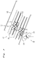
- each line connection mechanism 19 comprises upper and lower rotary shafts 22 each having two laterally spaced pulleys 21 mounted thereon for rotation together therewith.
- two laterally spaced endless belts 20 are trained between associated upper pulleys 21 on the leading side and those on the trailing side with respect to the direction of travel of notes.
- two laterally spaced endless belts 20 are trained between associated lower pulleys 21 on the leading side and those 21 on the trailing side.
- the line connection mechanisms 19 at the mating portions between two units enables power transmission from the body 11 to the connection unit U1.
- the line connection mechanisms 19 have a common connection construction, and the lower transport line L2 inside the body 11 and that inside each stacker unit are driven synchronously, thus transporting notes stably irrespective of the number of units.
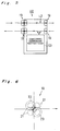
- Fig. 8 depicts each stacker unit having a vertically elongated box-like housing 30.
- the stacker unit has a storage space 34 defined therein and delimited by the housing 30, a vertically extending side wall 34a disposed inside the housing 30, and a horizontally extending elevating plate 35 mounted vertically movably inside the housing 30.
- Notes Y introduced into the stacker unit are stored one above the other on the elevating plate 35 and are fed out therefrom by a feed mechanism 36 disposed at an upper open end of the housing 30.
- the elevating plate 35 has a proximal end 35a vertically slidably mounted on a guide shaft 37 extending vertically along the side wall 34a of the storage space 34.
- the proximal end 35a of the elevating plate 35 is fixed to a belt 39 trained between upper and lower pulleys 38, which are rotatably mounted on upper and lower ends of the guide shaft 37, respectively.
- a drive motor (not shown) drives one of the pulleys 38 to rotate the belt 39 in an appropriate direction, thereby moving the elevating plate 35 up and down to allow storage of notes Y introduced in the storage space 34 or feed of such notes therefrom.
- the notes Y introduced in the storage space 34 fall to the elevating plate 35 and are horizontally placed one above the other thereon.
- a space required to allow the successively introduced notes Y to fall to the elevating plate 35 is formed above the elevating plate 35 because the vertical position of the elevating plate 35 is determined in accordance with the amount of notes Y stored in the storage space 34.
- the feed mechanism 36 comprises an auxiliary roller 40 disposed above the elevating plate 35 generally centrally of an open end of the storage space 34, a feed roller 41 disposed on the right-hand side of the open end of the storage space 34, as viewed in Fig. 8, a separation roller 42 disposed below and opposed to the feed roller 41, a contact roller (not shown) disposed immediately below the feed roller 41, and a pair of vaned discs 43 aligned with the contact roller on respective sides thereof and each having a plurality of radially extending vanes.
- the auxiliary roller 40 is allowed to intermittently rotate in only one direction to feed the notes Y placed on the elevating plate 35 with the topmost note held in contact with the auxiliary roller 40.
- the feed roller 41 is allowed to rotate in a direction to feed the notes Y into the storage space 34 and, also, in the opposite direction to feed the notes Y therefrom.
- the separation roller 42 can rotate in a direction to feed the notes Y into the storage space 34, but is prevented from rotating in the opposite direction.
- the contact roller and the vaned discs 43 can move vertically to move towards and away from the feed roller 41.
- the contact roller is brought into contact with the feed roller 41 so that the vaned discs 43 may rotate to knock off the notes Y onto the storage space 34.
- the contact roller and the vaned discs 43 are moved downwardly and are retained at a position spaced from the feed roller 41.
- the note transacting apparatus of the above-described construction operates as follows.
- the note transacting apparatus shown in Fig. 1 and having only the first and second stackers S1 and S2 incorporated in the body 11 thereof can be satisfactorily used for desired automatic transaction including deposit and withdrawal of notes.
- connection unit U1 When the note transacting apparatus is required to transact four kinds of notes or to store a single kind of notes in four separate stackers, the connection unit U1 is first removed from the body 11, and the additional stacker units U2 and U3 are subsequently interposed between the body 11 and the connection unit U1, as shown in Fig. 2.
- the number of stackers is made equal to that of the kinds of notes to be transacted or the single kind of notes can be stored in the four separate stackers, thus allowing an automatic transaction according to the object of utilization of the apparatus.
- the number of additional stacker units is not limited to two, but a required number thereof may be provided outside the body 11, depending on the object of utilization of the apparatus.
- a required number of stackers can be provided in correspondence to the number of the kinds of notes to be transacted. Therefore, it does not occur that the number of stackers is in excess or short.
- the note transacting apparatus of the present invention can be made compact and inexpensive because it can be effectively utilized in conformity with the number of the kinds of notes to be transacted.
- the additional stacker units are positioned outside the body 11, the driving power is synchronously transmitted from the latter to the former, thus enabling a stable transport.
- the elevating plate 35 is first moved downwardly to form a space thereabove required for the notes to fall thereto. Subsequently, the feed roller 41, the contact roller, and the vaned discs 43 are rotated to introduce the notes into the storage space 34. When falling, the notes are knocked off by the vanes of the vaned discs 43 onto the elevating plate 35 for the storage thereof inside the storage space 34. The elevating plate 35 is appropriately moved downwardly with an increase of the notes inside the storage space 34.
- the elevating plate 35 is moved upwardly to a position suited to feed the notes, while the auxiliary roller 40 is moved downwardly and held in contact with the topmost note to press the notes placed on the elevating plate 35 downwardly. Then, a continuous rotation of the feed roller 41 along with an intermittent rotation of the auxiliary roller 40 feeds a required number of notes successively from the elevating plate 35 to the outside of the storage space 34 via a transport path (not shown) with the notes separated by the separation roller 42 not rotating in the direction of feed of the notes. At this moment, the elevating plate 35 is appropriately moved upwardly with a decrease of the notes inside the storage space 34.
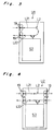
- FIGs. 9 and 10 depict modifications of the additional stacker units.
- An additional stacker unit U4 shown in Fig. 9 accommodates a lower transport line L2, a stacker S5 disposed below the lower transport line L2, and a driving motor M for driving the lower transport line L2.
- the driving motor M is disposed near the lower transport line L2 of the additional stacker unit U4 to drive it independently of the transport line L2 inside the body 11. Because the additional stacker unit U4 can generate the driving power, it is not necessary to transmit the driving power generated in the body 11 to the additional stacker unit U4. Accordingly, the transmission mechanism such as the power transmission gears or the like is dispensed with.
- An additional stacker unit U5 shown in Fig. 10 accommodates a lower transport line L2 made up of generally horizontally extending feed-in and feed-out lines L21 and L22, a stacker S6 disposed below the lower transport line L2, a curved connection line L23 branched from the feed-in line L21 to the feed-outline L22, and a direction-switching flapper F pivotally mounted at a branched position between the feed-in line L21 and the curved connection line L23.
- the direction-switching flapper F is operable to direct notes, that have arrived at the branched position, to either the horizontally extending feed-in line L21 or the curved connection line L23 extending downwardly therefrom.
- the curved connection line L23 provides a shortcut to the feed-out line L22.
- a required number of stackers can be prepared depending on the number of the kinds of notes to be transacted, by appropriately adjusting the number of the additional stacker units interposed between the body 11 and the existing connection unit U1. Because it does not occur that the number of stackers is in excess or short, the note transacting apparatus of the present invention can be effectively used in accordance with the object of utilization thereof.
- a single sheet transacting apparatus is applicable to various transactions in which the number of notes to be used differs, and the effective utilization of the stackers can reduce the size and the manufacturing cost of the apparatus.
- the claimed sheet storage apparatus corresponds to the body 11 of the apparatus.
- the claimed internal and external transport paths correspond to the lower transport line L2 inside the body 11 and the lower transport path L2 of the connection unit U1 or the additional stacker units U2 - U5, respectively.
- the claimed sheet storage portions communicated with the external transport path correspond to the stackers S2-S6 of the stacker units U2 - U5.
- the claimed first and second transport paths correspond to the feed-in and feed-out lines L21 and L22, respectively.
- the claimed power transmission means corresponds to the line connection mechanisms 19, while the claimed driving means corresponds to the driving motor M.
- the claimed branched connection path corresponds to the curved connection line L23, while the claimed direction-switching means corresponds to the direction-switching flapper F.
- the claimed transaction apparatus corresponds to the note transacting machine.
Landscapes
- Physics & Mathematics (AREA)
- General Physics & Mathematics (AREA)
- Business, Economics & Management (AREA)
- Accounting & Taxation (AREA)
- Finance (AREA)
- Pile Receivers (AREA)
- Separation, Sorting, Adjustment, Or Bending Of Sheets To Be Conveyed (AREA)
- Conveyance By Endless Belt Conveyors (AREA)
- Warehouses Or Storage Devices (AREA)
Applications Claiming Priority (3)
| Application Number | Priority Date | Filing Date | Title |
|---|---|---|---|
| JP08406694A JP3368347B2 (ja) | 1994-03-29 | 1994-03-29 | 紙葉類収納装置および取引処理装置 |
| JP8406694 | 1994-03-29 | ||
| JP84066/94 | 1994-03-29 |
Publications (2)
| Publication Number | Publication Date |
|---|---|
| EP0675465A1 true EP0675465A1 (fr) | 1995-10-04 |
| EP0675465B1 EP0675465B1 (fr) | 1999-07-07 |
Family
ID=13820128
Family Applications (1)
| Application Number | Title | Priority Date | Filing Date |
|---|---|---|---|
| EP95104617A Expired - Lifetime EP0675465B1 (fr) | 1994-03-29 | 1995-03-29 | Appareil de transaction avec des parties pour entreposer des feuilles |
Country Status (4)
| Country | Link |
|---|---|
| EP (1) | EP0675465B1 (fr) |
| JP (1) | JP3368347B2 (fr) |
| DE (1) | DE69510586T2 (fr) |
| ES (1) | ES2134968T3 (fr) |
Cited By (11)
| Publication number | Priority date | Publication date | Assignee | Title |
|---|---|---|---|---|
| WO2003038768A3 (fr) * | 2001-11-01 | 2003-11-13 | Jcm American Corp | Caisse d'argent liquide a double section et ensemble de validation de billet et de coupon |
| WO2003100735A1 (fr) | 2002-05-27 | 2003-12-04 | Japan Cash Machine Co., Ltd. | Dispositif de traitement de factures |
| EP1032477A4 (fr) * | 1997-11-28 | 2004-12-22 | Diebold Inc | Guichet automatique bancaire a recyclage des billets usages |
| DE102006058549A1 (de) * | 2006-12-12 | 2008-06-19 | Wincor Nixdorf International Gmbh | Vorrichtung und Verfahren zur Handhabung von Banknoten |
| DE102007028858A1 (de) * | 2007-06-22 | 2009-01-02 | Wincor Nixdorf International Gmbh | Wertscheinautomat |
| CN102874640A (zh) * | 2012-10-12 | 2013-01-16 | 深圳市怡化电脑有限公司 | 一种atm机下箱进出钞的方法和下箱结构 |
| DE102011115136A1 (de) * | 2011-10-07 | 2013-04-11 | Giesecke & Devrient Gmbh | Vorrichtung und Verfahren zur Bearbeitung von Banknoten |
| EP3333813A1 (fr) * | 2016-12-08 | 2018-06-13 | Masterwork Automodules Technology Corp., Ltd. | Appareil de manipulation de feuilles de papier |
| CN112753053A (zh) * | 2018-09-25 | 2021-05-04 | 劳雷尔银行机械株式会社 | 介质处理装置 |
| CN113646810A (zh) * | 2019-03-29 | 2021-11-12 | 劳雷尔银行机械株式会社 | 介质处理装置以及介质处理装置的单元连接方法 |
| US12223793B2 (en) | 2019-03-29 | 2025-02-11 | Laurel Bank Machines Co., Ltd. | Medium processing device and method of connecting units in medium processing device |
Families Citing this family (13)
| Publication number | Priority date | Publication date | Assignee | Title |
|---|---|---|---|---|
| EP0967581A3 (fr) | 1998-06-26 | 2004-06-09 | Hitachi, Ltd. | Machine pour déposer et distribuer des billets de banque |
| JP4135238B2 (ja) | 1998-12-08 | 2008-08-20 | 日立オムロンターミナルソリューションズ株式会社 | 紙幣入出金機 |
| JP4794715B2 (ja) * | 2000-02-22 | 2011-10-19 | グローリー株式会社 | 循環式紙幣入出金装置 |
| ES2287141T3 (es) | 2000-07-17 | 2007-12-16 | Japan Cash Machine Co., Ltd. | Un aparato de manejo de billetes. |
| JP4667663B2 (ja) * | 2001-07-09 | 2011-04-13 | 富士通コンポーネント株式会社 | プリンタ装置 |
| JP4408373B2 (ja) | 2004-01-23 | 2010-02-03 | 日立オムロンターミナルソリューションズ株式会社 | 紙幣入出金装置 |
| JP4733217B2 (ja) * | 2010-06-02 | 2011-07-27 | グローリー株式会社 | 紙葉類計数仕分機 |
| JP5039213B2 (ja) * | 2011-02-15 | 2012-10-03 | グローリー株式会社 | 紙葉類計数仕分機 |
| JP5091360B2 (ja) * | 2012-02-17 | 2012-12-05 | グローリー株式会社 | 紙葉類計数仕分機 |
| JP6380039B2 (ja) * | 2014-11-20 | 2018-08-29 | 沖電気工業株式会社 | 搬送路切替装置及び媒体取引装置 |
| CN104732650B (zh) * | 2015-03-27 | 2017-06-16 | 深圳怡化电脑股份有限公司 | 一种纸币的处理方法及系统 |
| JP6647110B2 (ja) * | 2016-03-29 | 2020-02-14 | ローレル精機株式会社 | 紙葉類処理装置の組立方法および紙葉類処理装置 |
| JP7171391B2 (ja) * | 2018-11-28 | 2022-11-15 | 日立チャネルソリューションズ株式会社 | 紙葉類仕分けシステム |
Citations (3)
| Publication number | Priority date | Publication date | Assignee | Title |
|---|---|---|---|---|
| DE2653979B2 (de) * | 1975-12-02 | 1979-09-06 | Inter Innovation Ab, Stockholm | Gerät zum Ausgeben von Banknoten, Fahrkarten o.dgl |
| EP0109743A2 (fr) * | 1982-09-29 | 1984-05-30 | Fujitsu Limited | Appareil pour le traitement de billets de banque |
| EP0473106A2 (fr) * | 1990-08-29 | 1992-03-04 | Hitachi, Ltd. | Appareil de traitement de billets de banque |
Family Cites Families (1)
| Publication number | Priority date | Publication date | Assignee | Title |
|---|---|---|---|---|
| GB9216806D0 (en) * | 1992-08-07 | 1992-09-23 | Ncr Int Inc | Apparatus for loading and picking sheets |
-
1994
- 1994-03-29 JP JP08406694A patent/JP3368347B2/ja not_active Expired - Fee Related
-
1995
- 1995-03-29 EP EP95104617A patent/EP0675465B1/fr not_active Expired - Lifetime
- 1995-03-29 DE DE69510586T patent/DE69510586T2/de not_active Expired - Lifetime
- 1995-03-29 ES ES95104617T patent/ES2134968T3/es not_active Expired - Lifetime
Patent Citations (3)
| Publication number | Priority date | Publication date | Assignee | Title |
|---|---|---|---|---|
| DE2653979B2 (de) * | 1975-12-02 | 1979-09-06 | Inter Innovation Ab, Stockholm | Gerät zum Ausgeben von Banknoten, Fahrkarten o.dgl |
| EP0109743A2 (fr) * | 1982-09-29 | 1984-05-30 | Fujitsu Limited | Appareil pour le traitement de billets de banque |
| EP0473106A2 (fr) * | 1990-08-29 | 1992-03-04 | Hitachi, Ltd. | Appareil de traitement de billets de banque |
Cited By (26)
| Publication number | Priority date | Publication date | Assignee | Title |
|---|---|---|---|---|
| EP1032477A4 (fr) * | 1997-11-28 | 2004-12-22 | Diebold Inc | Guichet automatique bancaire a recyclage des billets usages |
| US6889849B2 (en) | 2001-11-01 | 2005-05-10 | Jcm American Corporation | Dual cash box note and ticket validator |
| WO2003038768A3 (fr) * | 2001-11-01 | 2003-11-13 | Jcm American Corp | Caisse d'argent liquide a double section et ensemble de validation de billet et de coupon |
| GB2397159A (en) * | 2001-11-01 | 2004-07-14 | Jcm American Corp | Dual cash box note and ticket validator |
| GB2397159B (en) * | 2001-11-01 | 2005-03-02 | Jcm American Corp | Dual cash box note and ticket validator |
| RU2302038C2 (ru) * | 2002-05-27 | 2007-06-27 | Джэпэн Кэш Машин Ко., Лтд. | Автомат для обработки банкнот |
| KR101005835B1 (ko) * | 2002-05-27 | 2011-01-05 | 니혼긴센기카이가부시키가이샤 | 지폐취급 장치 |
| EP1510978A4 (fr) * | 2002-05-27 | 2007-08-01 | Nippon Kinsen Kikai Kk | Dispositif de traitement de factures |
| US7255216B2 (en) | 2002-05-27 | 2007-08-14 | Japan Cash Machine Co., Ltd. | Bill handling machine |
| AU2003241787B2 (en) * | 2002-05-27 | 2008-05-08 | Japan Cash Machine Co., Ltd. | Bill handling machine |
| CN100416614C (zh) * | 2002-05-27 | 2008-09-03 | 日本金钱机械株式会社 | 纸币处理装置 |
| WO2003100735A1 (fr) | 2002-05-27 | 2003-12-04 | Japan Cash Machine Co., Ltd. | Dispositif de traitement de factures |
| AU2003241787C1 (en) * | 2002-05-27 | 2009-01-15 | Japan Cash Machine Co., Ltd. | Bill handling machine |
| DE102006058549A1 (de) * | 2006-12-12 | 2008-06-19 | Wincor Nixdorf International Gmbh | Vorrichtung und Verfahren zur Handhabung von Banknoten |
| DE102007028858A1 (de) * | 2007-06-22 | 2009-01-02 | Wincor Nixdorf International Gmbh | Wertscheinautomat |
| US8985297B2 (en) | 2007-06-22 | 2015-03-24 | Wincor Nixdorf International Gmbh | Voucher machine |
| DE102011115136A1 (de) * | 2011-10-07 | 2013-04-11 | Giesecke & Devrient Gmbh | Vorrichtung und Verfahren zur Bearbeitung von Banknoten |
| CN102874640A (zh) * | 2012-10-12 | 2013-01-16 | 深圳市怡化电脑有限公司 | 一种atm机下箱进出钞的方法和下箱结构 |
| CN102874640B (zh) * | 2012-10-12 | 2015-11-18 | 深圳怡化电脑股份有限公司 | 一种atm机下箱进出钞的方法和下箱结构 |
| EP3333813A1 (fr) * | 2016-12-08 | 2018-06-13 | Masterwork Automodules Technology Corp., Ltd. | Appareil de manipulation de feuilles de papier |
| US10083563B2 (en) | 2016-12-08 | 2018-09-25 | Masterwork Automodules Tech Corp. Ltd | Paper sheet handling apparatus |
| CN112753053A (zh) * | 2018-09-25 | 2021-05-04 | 劳雷尔银行机械株式会社 | 介质处理装置 |
| CN112753053B (zh) * | 2018-09-25 | 2023-01-10 | 劳雷尔银行机械株式会社 | 介质处理装置 |
| US11842592B2 (en) | 2018-09-25 | 2023-12-12 | Laurel Bank Machines Co., Ltd. | Medium processing device |
| CN113646810A (zh) * | 2019-03-29 | 2021-11-12 | 劳雷尔银行机械株式会社 | 介质处理装置以及介质处理装置的单元连接方法 |
| US12223793B2 (en) | 2019-03-29 | 2025-02-11 | Laurel Bank Machines Co., Ltd. | Medium processing device and method of connecting units in medium processing device |
Also Published As
| Publication number | Publication date |
|---|---|
| JP3368347B2 (ja) | 2003-01-20 |
| DE69510586T2 (de) | 2000-03-02 |
| JPH07267513A (ja) | 1995-10-17 |
| EP0675465B1 (fr) | 1999-07-07 |
| ES2134968T3 (es) | 1999-10-16 |
| DE69510586D1 (de) | 1999-08-12 |
Similar Documents
| Publication | Publication Date | Title |
|---|---|---|
| EP0675465B1 (fr) | Appareil de transaction avec des parties pour entreposer des feuilles | |
| US6942207B2 (en) | Bill receiving/dispensing box | |
| US7428983B2 (en) | Banknote receipt and payout apparatus | |
| EP1489563A1 (fr) | Appareil pour recevoir et payer du papier-monnaie et machine automatique de guichet | |
| JPH02231360A (ja) | 紙葉類の搬送放出回収機構 | |
| KR100961578B1 (ko) | 금융자동화기기 및 금융자동화기기에서의 매체 리젝트 방법 | |
| KR900009173Y1 (ko) | 지폐출납기의 지폐누름 장치 | |
| JP3418896B2 (ja) | 紙葉類収納繰出し装置および紙葉類処理装置 | |
| JPH09227011A (ja) | 紙葉類の搬送装置および紙幣入出金機 | |
| JP3552819B2 (ja) | 紙幣収納庫 | |
| KR940001008Y1 (ko) | 현금 자동 지급기 | |
| JP3018719B2 (ja) | 紙幣識別装置 | |
| KR100603522B1 (ko) | 지폐자동지급기의 고객취납장치 | |
| JP4206242B2 (ja) | 紙幣取扱装置 | |
| US4708335A (en) | Sheet presenting assembly | |
| JP2581540B2 (ja) | 紙葉類搬送システム | |
| JP3502179B2 (ja) | 紙幣払出装置における札揃え装置 | |
| JPH0521174Y2 (fr) | ||
| JPS6337066A (ja) | 紙葉類処理装置 | |
| JP4161233B2 (ja) | 紙幣処理装置 | |
| JP4011195B2 (ja) | 紙幣入出金機 | |
| KR20090073737A (ko) | 금융자동화기기 | |
| JP2792805B2 (ja) | 紙葉保留装置 | |
| KR950004414Y1 (ko) | 현금 자동지급기의 지폐 정렬 장치 | |
| JPS6153301B2 (fr) |
Legal Events
| Date | Code | Title | Description |
|---|---|---|---|
| PUAI | Public reference made under article 153(3) epc to a published international application that has entered the european phase |
Free format text: ORIGINAL CODE: 0009012 |
|
| 17P | Request for examination filed |
Effective date: 19950427 |
|
| AK | Designated contracting states |
Kind code of ref document: A1 Designated state(s): DE ES FR GB IT NL PT SE |
|
| 17Q | First examination report despatched |
Effective date: 19961217 |
|
| GRAG | Despatch of communication of intention to grant |
Free format text: ORIGINAL CODE: EPIDOS AGRA |
|
| GRAG | Despatch of communication of intention to grant |
Free format text: ORIGINAL CODE: EPIDOS AGRA |
|
| GRAH | Despatch of communication of intention to grant a patent |
Free format text: ORIGINAL CODE: EPIDOS IGRA |
|
| GRAH | Despatch of communication of intention to grant a patent |
Free format text: ORIGINAL CODE: EPIDOS IGRA |
|
| GRAH | Despatch of communication of intention to grant a patent |
Free format text: ORIGINAL CODE: EPIDOS IGRA |
|
| GRAA | (expected) grant |
Free format text: ORIGINAL CODE: 0009210 |
|
| AK | Designated contracting states |
Kind code of ref document: B1 Designated state(s): DE ES FR GB IT NL PT SE |
|
| REF | Corresponds to: |
Ref document number: 69510586 Country of ref document: DE Date of ref document: 19990812 |
|
| ET | Fr: translation filed | ||
| ITF | It: translation for a ep patent filed | ||
| REG | Reference to a national code |
Ref country code: ES Ref legal event code: FG2A Ref document number: 2134968 Country of ref document: ES Kind code of ref document: T3 |
|
| REG | Reference to a national code |
Ref country code: PT Ref legal event code: SC4A Free format text: AVAILABILITY OF NATIONAL TRANSLATION Effective date: 19990929 |
|
| PLBE | No opposition filed within time limit |
Free format text: ORIGINAL CODE: 0009261 |
|
| STAA | Information on the status of an ep patent application or granted ep patent |
Free format text: STATUS: NO OPPOSITION FILED WITHIN TIME LIMIT |
|
| 26N | No opposition filed | ||
| REG | Reference to a national code |
Ref country code: GB Ref legal event code: IF02 |
|
| REG | Reference to a national code |
Ref country code: GB Ref legal event code: 732E |
|
| NLS | Nl: assignments of ep-patents |
Owner name: HITACHI-OMRON TERMINAL SOLUTIONS, CORP. Effective date: 20060327 |
|
| PGFP | Annual fee paid to national office [announced via postgrant information from national office to epo] |
Ref country code: PT Payment date: 20100316 Year of fee payment: 16 Ref country code: ES Payment date: 20100324 Year of fee payment: 16 |
|
| PGFP | Annual fee paid to national office [announced via postgrant information from national office to epo] |
Ref country code: IT Payment date: 20100323 Year of fee payment: 16 Ref country code: FR Payment date: 20100324 Year of fee payment: 16 |
|
| PGFP | Annual fee paid to national office [announced via postgrant information from national office to epo] |
Ref country code: GB Payment date: 20100322 Year of fee payment: 16 |
|
| PGFP | Annual fee paid to national office [announced via postgrant information from national office to epo] |
Ref country code: NL Payment date: 20100316 Year of fee payment: 16 Ref country code: DE Payment date: 20100429 Year of fee payment: 16 |
|
| PGFP | Annual fee paid to national office [announced via postgrant information from national office to epo] |
Ref country code: SE Payment date: 20100310 Year of fee payment: 16 |
|
| REG | Reference to a national code |
Ref country code: PT Ref legal event code: MM4A Free format text: LAPSE DUE TO NON-PAYMENT OF FEES Effective date: 20110929 |
|
| REG | Reference to a national code |
Ref country code: NL Ref legal event code: V1 Effective date: 20111001 |
|
| REG | Reference to a national code |
Ref country code: SE Ref legal event code: EUG |
|
| GBPC | Gb: european patent ceased through non-payment of renewal fee |
Effective date: 20110329 |
|
| REG | Reference to a national code |
Ref country code: FR Ref legal event code: ST Effective date: 20111130 |
|
| PG25 | Lapsed in a contracting state [announced via postgrant information from national office to epo] |
Ref country code: DE Free format text: LAPSE BECAUSE OF NON-PAYMENT OF DUE FEES Effective date: 20111001 Ref country code: FR Free format text: LAPSE BECAUSE OF NON-PAYMENT OF DUE FEES Effective date: 20110331 Ref country code: NL Free format text: LAPSE BECAUSE OF NON-PAYMENT OF DUE FEES Effective date: 20111001 |
|
| REG | Reference to a national code |
Ref country code: DE Ref legal event code: R119 Ref document number: 69510586 Country of ref document: DE Effective date: 20111001 |
|
| PG25 | Lapsed in a contracting state [announced via postgrant information from national office to epo] |
Ref country code: GB Free format text: LAPSE BECAUSE OF NON-PAYMENT OF DUE FEES Effective date: 20110329 Ref country code: IT Free format text: LAPSE BECAUSE OF NON-PAYMENT OF DUE FEES Effective date: 20110329 |
|
| REG | Reference to a national code |
Ref country code: ES Ref legal event code: FD2A Effective date: 20120424 |
|
| PG25 | Lapsed in a contracting state [announced via postgrant information from national office to epo] |
Ref country code: ES Free format text: LAPSE BECAUSE OF NON-PAYMENT OF DUE FEES Effective date: 20110330 |
|
| PG25 | Lapsed in a contracting state [announced via postgrant information from national office to epo] |
Ref country code: SE Free format text: LAPSE BECAUSE OF NON-PAYMENT OF DUE FEES Effective date: 20110330 |
|
| PG25 | Lapsed in a contracting state [announced via postgrant information from national office to epo] |
Ref country code: PT Free format text: LAPSE BECAUSE OF NON-PAYMENT OF DUE FEES Effective date: 20111012 |