EP0675480A2 - Keyboard musical instrument having variable contact point between jack and regulating button - Google Patents
Keyboard musical instrument having variable contact point between jack and regulating button Download PDFInfo
- Publication number
- EP0675480A2 EP0675480A2 EP95104834A EP95104834A EP0675480A2 EP 0675480 A2 EP0675480 A2 EP 0675480A2 EP 95104834 A EP95104834 A EP 95104834A EP 95104834 A EP95104834 A EP 95104834A EP 0675480 A2 EP0675480 A2 EP 0675480A2
- Authority
- EP
- European Patent Office
- Prior art keywords
- regulating
- hammer
- musical instrument
- keyboard musical
- buttons
- Prior art date
- Legal status (The legal status is an assumption and is not a legal conclusion. Google has not performed a legal analysis and makes no representation as to the accuracy of the status listed.)
- Granted
Links
- 230000001105 regulatory effect Effects 0.000 title claims abstract description 186
- 230000007246 mechanism Effects 0.000 claims abstract description 121
- 230000000712 assembly Effects 0.000 claims description 28
- 238000000429 assembly Methods 0.000 claims description 28
- 230000009471 action Effects 0.000 claims description 25
- 230000033001 locomotion Effects 0.000 claims description 20
- 230000000903 blocking effect Effects 0.000 claims description 11
- 230000008859 change Effects 0.000 claims description 7
- 230000005236 sound signal Effects 0.000 description 19
- 230000000994 depressogenic effect Effects 0.000 description 12
- 230000015654 memory Effects 0.000 description 12
- 230000001276 controlling effect Effects 0.000 description 9
- 230000000881 depressing effect Effects 0.000 description 7
- 241000251131 Sphyrna Species 0.000 description 6
- 239000004744 fabric Substances 0.000 description 6
- 230000004048 modification Effects 0.000 description 5
- 238000012986 modification Methods 0.000 description 5
- 238000001228 spectrum Methods 0.000 description 5
- 230000003247 decreasing effect Effects 0.000 description 4
- 238000001914 filtration Methods 0.000 description 4
- 230000000284 resting effect Effects 0.000 description 4
- 230000007423 decrease Effects 0.000 description 3
- 230000001681 protective effect Effects 0.000 description 3
- XEEYBQQBJWHFJM-UHFFFAOYSA-N Iron Chemical compound [Fe] XEEYBQQBJWHFJM-UHFFFAOYSA-N 0.000 description 2
- 230000006399 behavior Effects 0.000 description 2
- 239000010985 leather Substances 0.000 description 2
- 238000005070 sampling Methods 0.000 description 2
- 125000006850 spacer group Chemical group 0.000 description 2
- 229910000838 Al alloy Inorganic materials 0.000 description 1
- 238000013459 approach Methods 0.000 description 1
- 238000010586 diagram Methods 0.000 description 1
- 230000000694 effects Effects 0.000 description 1
- 230000008030 elimination Effects 0.000 description 1
- 238000003379 elimination reaction Methods 0.000 description 1
- 230000006870 function Effects 0.000 description 1
- 229910052742 iron Inorganic materials 0.000 description 1
- 230000002035 prolonged effect Effects 0.000 description 1
- 238000004080 punching Methods 0.000 description 1
- 230000004044 response Effects 0.000 description 1
- 229920003002 synthetic resin Polymers 0.000 description 1
- 239000000057 synthetic resin Substances 0.000 description 1
- 239000002023 wood Substances 0.000 description 1
- 230000003936 working memory Effects 0.000 description 1
Images


Classifications
-
- G—PHYSICS
- G10—MUSICAL INSTRUMENTS; ACOUSTICS
- G10C—PIANOS, HARPSICHORDS, SPINETS OR SIMILAR STRINGED MUSICAL INSTRUMENTS WITH ONE OR MORE KEYBOARDS
- G10C3/00—Details or accessories
- G10C3/16—Actions
Definitions
- This invention relates to a keyboard musical instrument and, more particularly, to a keyboard musical instrument having a variable contact point between a jack and a regulating button depending upon a mode of operation.
- the capstan button 110 After the contact with the drop screw 107e, the capstan button 110 still rises, and rotates the repetition lever 106d in the clockwise direction in figure 1 between point S and point B. As a result, the contact point between the hammer roller 107c and the repetition lever 106d gently rises.
- the rise h is about 0.4 millimeter.
- the silent system 200 comprises a shank stopper 210 changeable between a free position FP and a blocking position BP and a change-over mechanism 230 connected to the shank stopper 210.
- the shank stopper 210 is provided in a space between the strings 104 and the hammer shanks 107b at the home position, and is split into two stopper sections (see figure 10). One of the stopper sections is provided for the sets of strings assigned to low-pitched tones, and the other stopper section is provided for the sets of strings assigned to middle-pitched tones and high-pitched tones.
- the shank stopper 210 comprises a rod member 211 split into two sections 211a and 211b, cushion brackets 212a and 212b respectively attached to the two sections 211a and 211b, lower cushion members 213a and 213b attached to the cushion brackets 212a and 212b, upper cushion members 214a and 214b fixed to the lower cushion members 213a and 213b and protective skins 215a and 215b fixed to the upper cushion members 214a and 214b.
- the lower cushion members 213a and 213b, the upper cushion members 214a and 214b and the protective skins 215a and 215b form a cushion unit 216.
- the shank stopper 210 retracts the cushion unit 216 in an upper space higher than the lower surface of the pin board PB (see figure 1), and the keyboard 101, the key action mechanisms 106 and the hammer assemblies 107 can be taken out together without an interruption of the shank stopper 210 for a tuning operation.
- the plurality of key sensors 302 is respectively associated with the plurality of black and white keys 101a and 101b, and each of the key sensors 302 comprises a shutter plate fixed to the bottom surface of the associated key 101a/101b and photo-interrupters mounded on the key frame 102 along the respective paths of the associated shutter plates.
- the shutter plate is moved together with the associated key 101a/101b, and the photo-interrupters monitors the motion of the associated shutter plate and, accordingly, the motion of the associated key 101a/101b.
- the key sensors 302 supply the controlling unit 301 key position signals each indicative of a current key position of the associated key 101a/101b.
- the plurality sets of pcm data codes are produced with a sampler (not shown) through sampling of actual vibrations on the sets of strings 104 at appropriate sampling frequency.
- the set of pcm data codes may be produced by means of the data processor 301f in a real-time manner.
- the data processor 301f for sound spectrum can produce not only a group of pcm data codes indicative of frequency spectrum for original vibrations but also a set of pcm data codes indicative of frequency specular for resonant vibrations as described hereinbefore.
- the data processor 301f is further operative to cause the frequency specular to decay.
- original vibrations on a set of strings rapidly decays, because an associated damper head is brought into contact with the strings.
- the data processor 301f simulates the decay of the vibrations in the acoustic piano, and sequentially decreases the values of the pcm data codes.
- the audio signal generator 301j comprises a digital filter, a digital-to-analog converter and a low-pass filter, and produces the analog audio signal AD from the pcm data codes supplied from the data memories 301b and 301d and/ or the data processors 301c, 301e and 301f.
- the pcm data codes are subjected to a digital filtering, and are, then, converted into the analog audio signal AD. If a speaker system is employed, the vibration characteristics of the speaker system and vibratory characteristics of the speaker box are taken into account for the digital filtering, and the pcm data codes are modified in such a manner that the frequency spectrum of produced sounds becomes flat.
- the digital filter is of the FIR type. However, an IIR type digital filter is available. An oversampling type digital filter may follow the digital filtering for eliminating quantized noises.
- the regulating button mechanism 600 is simpler than that of the first embodiment, and the keyboard musical instrument implementing the fourth embodiment achieves all of the advantages described in conjunction with the first embodiment.
- the jack 650 has a long portion 650a and a short portion 650b, and the regulating button mechanism 651 comprises a rotatable shaft 651a and a plurality of projection 651b each opposed to the short portion 650b of the jack 650.
- the acoustic piano 800 is a standard upright piano, and parts of the acoustic piano 800 are labeled with the same references designating corresponding parts of the grand piano 100.
- the hammer assemblies 107 are resting on a hammer rail 801, and the long portion 106h of the jack 106e is held in contact with a hammer butt 802 of the hammer assembly 107.
- the capstan button 110 upwardly pushes the whippen assembly 106b, and rotates the whippen assembly 106b around the whippen flange 106a.
- the short portion 106i is brought into contact with a regulating button mechanism 850, and the jack 106e escapes from the hammer butt 802.
Landscapes
- Physics & Mathematics (AREA)
- Engineering & Computer Science (AREA)
- Acoustics & Sound (AREA)
- Multimedia (AREA)
- Electrophonic Musical Instruments (AREA)
Abstract
Description
- This invention relates to a keyboard musical instrument and, more particularly, to a keyboard musical instrument having a variable contact point between a jack and a regulating button depending upon a mode of operation.
- A piano is a typical example of the keyboard musical instrument. The piano generates a loud sound through an impact of a hammer on a set of strings, and the player is afraid that the loud sounds disturb the neighborhood. For this reason, a piano is equipped with a muting/silent mechanism for muting the loudness of the sounds.
- A prior art muting mechanism is constituted by a cushion member and a driving mechanism, and the driving mechanism moves the cushion member onto the strings. While a player is performing a music, the hammer assemblies rebound on the cushion member, and softly strike the sets of strings. The cushion member rapidly takes up the vibrations of the strings, and the strings generate soft sounds.
- U.S. Patent No. 2,250,065 discloses a prior art silent mechanism, and the disclosed silent mechanism picks up the hammer assemblies so as to cut off the functional relation between the key action mechanisms and the hammer assemblies. Even if a player depresses the keys, the depressed keys actuate only the associated key action mechanisms: however, the key action mechanisms do not drive the hammer assemblies for rotation. Thus, the strings are not struck by the hammer assemblies, and a sound is not generated by the piano. If key sensors and/or hammer sensors are provided for the piano equipped with the silent mechanism, a tone generator may generate electronic sounds on the basis of the detected key/hammer motions.
- The prior art muting mechanism can not perfectly eliminate the sounds from the piano, and the prior art silent mechanism changes the key-touch unique to the acoustic piano, because an escape of the jack from the hammer roller gives the unique key-touch to the player. Namely, while a player is depressing a key, the jack is escaped from the hammer roller, and players's finger suddenly feels light due to the elimination of the hammer weight.
- Japanese Patent Application No. 4-174813 proposed a silent mechanism for an acoustic piano, and U.S. Serial No. 08/073,092 was filed claiming the priority right on the basis of Japanese Patent Application No. 4-174813 together with other Japanese Patent Applications. Although several prior arts opposed against U.S. Serial No. 08/073,092, the U.S. Patent Application was patented, and U.S. Patent No. 5,374,775 was issued on December 20, 1994. The references cited in the patent prosecution are U.S. Patent documents 2,250,065, 4,633,753, 4,704,931 , 4,744,281 , 4,970,929, 5,115,705 and 5,247,129 and Foreign Patent documents 44782 (Germany), 68406 (Germany), 97885 (Germany), 3707591 (Germany) and 3707591C1 (Germany), To9-1U000077 (Italy), 51-67732 (Japan), 55-55880 (Japan), 62-32308 (Japan), 63-97997 (Japan) and 614303 (Switzerland).
- The silent mechanism disclosed in U.S. Patent No. 5,374,775 moves a stopper into and out of the paths of the hammer shanks, and the hammer shank rebounds on the stopper staying in the paths of the hammer shanks before an impact on the strings.
- However, the silent mechanism disclosed in U.S. Patent No. 5,374,775 requires a wide space between the strings and the hammer heads in the home position, and is hardly installed in a small-sized piano and some kind of piano with a narrow space between the hammers and the strings. In detail, when deformation of a hammer shank and the stopper is taken into account, the silent mechanism requires a gap ranging from 5 to 10 millimeters between the hammer heads and the strings at the reboud of the hammer shanks on the stopper so as to prevent the strings from the hammer heads. On the other hand, although the escape point is variable depending upon the notes assigned the strings, the escape point of a kind of piano is regulated to 3 millimeters for low-pitched tones, 2.5 millimeters for middle-pitched tones and 2 millimeters for high-pitched tones. If the silent mechanism is effective, the hammer shanks are brought into contact with the stopper before the escape of the jacks from the hammer rollers, and are caught between the stopper and the jacks.
- Japanese Patent Application No. 4-215400 discloses a regulating mechanism for changing the escape point, and U.S. Serial No. 08/174,179 and European Patent Application No. 93120645.2 were filed claiming the priority rights on the basis of Japanese Patent Application No. 4-215400 together with other Japanese Patent Applications. The regulating mechanism disclosed in Japanese Patent Application No. 4-215400 has a spacer insertable into a gap between the toe of the jack and the regulating button, and the spacer allows the jack to escape from the hammer butt (or the hammer roller) earlier than the escap after the direct contact between the jack and regulating button.
- However, the jack early escaping from the hammer butt or the hammer roller causes the player to feed the key-touch shallow. The shallow key-touch may not be serious to a beginner. However, professional pianists hate the shallow key-touch.
- It is therefore an important object of the present invention to provide a keyboard musical instrument which is equipped with a mechanism increasing a gap between a hammer head and strings at a finish of an escape without change of a starting point of the escape for a key-touch unique to a piano.
- To accomplish the object, the present invention proposes to change a contact point between a short portion of a jack and a regulating button mechanism.
- In accordance with the present invention, there is provided a keyboard musical instrument comprising: a plurality of keys respectively assigned notes of a scale, and selectively moved by a player; a plurality of string means associated with the plurality of keys for generating acoustic tones having the notes, respectively; a plurality of hammer assemblies respectively associated with the plurality of string means for striking the associated string means when the player selectively depresses the plurality of keys, a plurality of key action mechanisms functionally connected between the plurality of keys and the plurality of hammer assemblies, respectively, and each including a whippen assembly rotated by the associated key moved by the player, a regulating button mechanism, and a jack having a long portion and a short portion merged with the long portion at an intermediate portion rotatably supported by the whippen assembly and brought into contact with the regulating button mechanism for escaping from the associated hammer assembly; and a change-over means associated with the regulating button mechanism for changing a contact point between the short portion and the regulating button mechanism.
- The keyboard musical instrument may further comprise a stopper for preventing the plurality of string means from impacts of the hammer assemblies and an electronic sound generating system for generating electronic sounds in response to the keys depressed by the player.
- The features and advantages of the keyboard musical instrument according to the present invention will be more clearly understood from the following description taken in conjunction with the accompanying drawings in which:
- Fig. 1 is a cross sectional view showing the structure of a keyboard musical instrument according to the present invention;
- Fig. 2 is a side view showing a regulating button mechanism incorporated in the keyboard musical instrument at a starting point of an escape according to the present invention;
- Fig. 3 is a cross sectional view showing a second regulating button incorporated in the regulating button mechanism;
- Fig. 4 is a front view showing second regulating buttons incorporated in the keyboard musical instrument;
- Fig. 5 is a front view showing a part of the second regulating buttons;
- Fig. 6 is a graph showing relation between a key motion and a motion of capstan button;
- Fig. 7 is a graph showing relation between the key motion and a contact point between a repetition lever and a hammer roller;
- Fig. 8 is a graph showing relation between the key motion and a hammer motion;
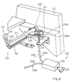
- Fig. 9 is a perspective view showing a silent system incorporated in the keyboard musical instrument;
- Fig. 10 is a perspective view showing the silent system from another angle;
- Fig. 11 is a block diagram showing the arrangement of an electronic sound generating system incorporated in the keyboard musical instrument;
- Fig. 12 is a side view showing a regulating button mechanism in a silent/muting modes incorporated in another keyboard musical instrument at a starting point of an escape according to the present invention;
- Fig. 13 is a side view showing the regulating button mechanism at a starting point of an escape in a standard acoustic sound mode;
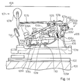
- Fig. 14 is a side view showing a regulating button mechanism incorporated in yet another keyboard musical instrument at a starting point of an escape according to the present invention;
- Fig. 15 is a side view showing a regulating button mechanism at a starting point of an escape in a silent/muting modes incorporated in still another keyboard musical instrument according to the present invention;
- Fig. 16 is a side view showing the regulating button mechanism at a starting point of an escape in a standard acoustic sound mode;
- Fig. 17 is a side view showing a jack and a regulating button mechanism incorporated in a keyboard musical instrument according to the present invention;
- Fig. 18 is a side view showing a regulating button mechanism incorporated in another keyboard musical instrument according to the present invention; and
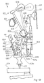
- Fig. 19 is a side view showing a regulating button mechanism incorporated in a keyboard musical instrument according to the present invention.
- Referring first to figure 1 of the drawings, a keyboard musical instrument embodying the present invention largely comprises a
grand piano 100, a silent system 200 and an electronicsound generating system 300, and selectively enters into at least a standard acoustic sound mode, a muting mode and a silent mode. The grand piano is a standard type, and a piano case (not shown) houses most of internal mechanisms of thegrand piano 100. In the following description, a rotational direction is determined in a figure to be referenced, and a player sits on the front side of the keyboard musical instrument during a performance. - The
grand piano 100 comprises akeyboard 101 supported by akey frame 102 mounted on akey bed 103. Eighty-eight black andwhite keys keyboard 101, and are turnable with respect tobalance pins 104. The black andwhite keys white keys white keys white keys white keys white keys - The
grand piano 101 further comprises a plurality of sets ofstrings 104 horizontally stretched between tuning pins (not shown) and hitch pins (not shown) over thekeyboard 101, awhippen rail 105 laterally extending over the rear end portions of the black andwhite keys key action mechanisms 106 supported by thewhippen rail 105 and a plurality ofhammer assemblies 107 turnably supported by ahammer shank rail 109. Action brackets support thewhippen rail 105 and theshank flange rail 109. Theaction brackets 108, the black andwhite keys 101a/101b and thekey frame 102 are laterally movable by means of a shift pedal (not shown), and cause thehammer assemblies 107 to strike the strings fewer than the normal number for lessening the softening the timbre and prolonging the tones. The sets ofstrings 104 respectively vibrate, and generate acoustic tones with the notes of the scale assigned to the black andwhite keys - The plurality of
key action mechanisms 106 are similar in structure to one another, and are functionally connected to the black andwhite keys white keys key action mechanisms 106 are actuated by the capstan screws 110, and rotate the associatedhammer assemblies 107 toward the sets ofstrings 104. Thehammer assemblies 107 rebound on the sets ofstrings 104, and return to respective home positions shown in figure 1. - The
grand piano 100 further comprises a plurality ofdamper mechanisms 111 movably supported by adamper lever rail 112. Thedamper mechanisms 111 are respectively held in contact with the sets ofstrings 104 while the black andwhite keys strings 104 to vibrate. Thedamper mechanisms 111 is respectively actuated by the rear end portions of the black andwhite keys strings 104. Then, thestrings 104 are allowed to vibrate, and generate the acoustic tones, respectively. - Each of the
key action mechanisms 106 comprises a whippen flange 106a fixed to thewhippen rail 105, anwhippen assembly 106b turnably supported by the whippen flange 106a, arepetition lever flange 106c fixed to an intermediate portion of thewhippen assembly 106b, arepetition lever 106d turnably supported by therepetition lever flange 106c, ajack 106e turnably supported by a front end portion of thewhippen assembly 106b, arepetition spring 106f urging therepetition lever 106d and thejack 106e in the counter clockwise direction and aregulating button mechanism 106g supported by thehammer shank rail 109. - The
hammer assemblies 107 are also similar to one another, and eachhammer assembly 107 comprises ahammer shank flange 107a fixed to thehammer shank rail 109, ahammer shank 107b turnably connected to thehammer shank flange 107b, ahammer roller 107c fixed to thehammer shank 107b and ahammer head 107d fixed to the leading end of thehammer shank 107b. - The
jack 106e has an L-shape, and is broken down into along portion 106h and ashort portion 106i. Thelong portion 106h passes through an aperture formed in therepetition lever 106d, and thehammer assembly 107 at the home position causes thehammer roller 107c to stay on the top surface of thelong portion 106h of thejack 106e. On the other hand, theshort portion 106i is opposed to theregulating button mechanism 106g while the black/white key 101a/101b is resting. Therepetition spring 106f urges thejack 106e in the counter clockwise direction at all times, and ajack button 106j backwardly projects from thelong portion 106h is pressed against ajack stop spoon 106k fixed to thewhippen assembly 106b while theshort portion 106i is spaced from theregulating button mechanism 106g. - The
repetition lever 106d is urged in the counter clockwise direction at all times, and arepetition lever button 106m is pressed against the rear end portion of thewhippen assembly 106b. - While the
hammer assembly 107 is staying at the home position, thehammer roller 107c rests on a top surface of thelong portion 106h of thejack 106e, and the hammer shank stop felt 106n is fixed to the rear end portion of thewhippen assembly 106b. Adrop screw 107e downwardly projects from thehammer shank flange 107a, and regulates the amount of return distance from the closest point when a player softly depressing the associated key. - As will be better seen in figures 2 and 3 of the drawings, first and second
semi-spherical portions 106o and 106p are formed on theshort portion 106i of thejack 106e, and the first semi-spherical portion 106o is usually called as "toe". - The
regulating button mechanism 106g associated with eachjack 106e comprises a first regulating screw 106q inserted into afirst regulating rail 113 screwed into thehammer shank rail 109, afirst regulating button 106r fixed to the first regulating screw 106q, asecond regulating button 106s engageable with the secondsemi-spherical portion 106p and a change-over sub-mechanism 106t shared with othersecond regulating buttons 106s. In this instance, the distance between the rotational axis of thejack 106e and the first semi-spherical portion 106o is twice as long as the distance between the rotational axis of thejack 106e and the secondsemi-spherical portion 106p. - Assuming now that the key 101a/101b is depressed at a certain speed, the
jack 106e brought into contact with thesecond regulating button 106s at the secondsemi-spherical portion 106p gives a smaller force to thehammer assembly 107 than thejack 106e brought into contact with theregulating button 106r at the first semi-spherical portion 106o. Moreover, the transmitting time period of the former is shorter than the transmitting time period of the latter. As a result, thehammer assembly 107 associated with the former slowly turns around theshank flange 107a, and gently rebounds on the strings for producing a soft acoustic tone. - However, the starting point of escape is not changed between the
first regulating button 106r and thesecond regulating button 106s, and the key-touch unique to the grand piano is given to the player in all of the modes of operation. - As will be better seen from figures 4 and 5, each of the
second regulating buttons 106s is associated with one of the plurality of groups ofkey action mechanisms 106, and, accordingly, thekey action mechanisms 106 of each group share thesecond regulating buttons 106s. - The change-
over sub-mechanism 106t comprises a secondregulating rail bracket 106u bolted to thehammer shank rail 109 and arod member 106v rotatably supported by means of bearingunits 106w on the secondregulating rail bracket 106u, and thesecond regulating buttons 106s are split into a plurality of sections respectively corresponding to the groups of thekey action mechanisms 106. Cloth members 106wa are inserted between the inner surfaces of the bearingunits 106w and therod member 106v, and allow therod member 106v to be smoothly rotated. - Each
second regulating button 106s comprises a threadedstem portion 106x screwed into each of bush members 106va inserted into through holes formed in therod member 106v at intervals, abracket 106y fixed to the leading end of the threadedstem portion 106x, cloth punchings 106za and 106zb inserted between thebracket 106y and the head portion of the threadedstem portion 106x and a cloth member 106zc attached to the lower surface of thebracket 106y. Thebracket 106y is split into two peaces, and the threadedstem portion 106x is rotatable in thebracket 106y. A cubic head 106xa is formed at the opposite end of the threadedstem portion 106x, and a tuner can rotate the threadedstem portion 106x with a wrench. Therefore, the gap between the secondsemi-spherical portion 106p and the cloth member 106zc is regulatable by turning the threadedstem portion 106x. Therod member 106v is shared between all of thesecond regulating buttons 106s, and a manipulatinggrip 116 is connected through aflexible wire 117 to connectingrods 118 implanted into therod member 106v. The manipulatinggrip 116 is slidable in acase 119 attached to thekey bed 103. - Though not shown in the drawings, a spring urges the connecting
rods 118 in the counter clockwise direction, and thesecond regulating buttons 106s are changed to an idling position indicated by dots-and-dash line in figure 2. While the keyboard musical instrument is being performed in the standard acoustic sound mode, the spring maintains thesecond regulating buttons 106s in the idling position. On the other hand, when the keyboard musical instrument enters into the muting mode or the silent mode, the manipulatinggrip 116 is pulled toward the front side, and the connectingrods 118 rotate therod member 106v in the clockwise direction against the elastic force of the spring (not shown). Then, thesecond regulating buttons 106s is changed to an active position, and the cloth members 106zc are opposed to the secondsemi-spherical portions 106p. - The regulating
rail 113 is split into a plurality of regulating rail sections, and the regulating rail sections are corresponding to a plurality of groups of action mechanisms. Thefirst regulating button 106r is opposed to the first semi-spherical portion 106o, and the gap d between the first semi-spherical portion 106o and thefirst regulating button 106r is regulatable by turning thefirst regulating button 106r. A starting point of escape of thejack 106e is determined by the gap d, and is usually regulated in such a manner that thehammer head 107d reaches 2-3 millimeters from the associated set ofstrings 104. If the gap d is decreased, the starting point of escape becomes early. On the other hand, if the gap d is increased, the starting point of escape becomes late. - Turning back to figure 1, while a black/white key 101a/101b is traveling from the rest position to the end position, the
capstan button 110 upwardly pushes thewhippen assembly 106b, and thewhippen assembly 106b and thejack 106e turn around the whippen flange 106a in the counter clockwise direction. Thejack 106e turning around the whippen flange 106a causes thehammer assembly 106d to turn around theshank flange 107a in the clockwise direction. When one of the first and secondsemi-spherical portions 106o and 106p is brought into contact with the first or second regulating button, thewhippen assembly 106b still turning around the whippen flange 106a causes thejack 106e to turn around a pin PN in the clockwise direction against the elastic force of therepetition spring 106f. Then, thejack 106e escapes from thehammer roller 107c, and thehammer assembly 107 rushes toward the set ofstrings 104. - The
hammer head 107d rebounds on the set ofstrings 104, and thehammer roller 107c is brought into contact with therepetition lever 106d. Thehammer roller 107c impacts on therepetition lever 106d, and therepetition lever 106d turns around therepetition flange 106c in the clockwise direction against the elastic force of therepetition spring 106f. Thehammer assembly 107 is finally received by a back-check 114. On the other hand, when the black/white key 101a/101b is slightly lifted from the end position, thehammer head 107d is released from theback check 114, and therepetition spring 106f rotates therepetition lever 106d in the counter clockwise direction. As a result, thehammer assembly 107 turns in the clockwise direction over a small angle, and thejack 106e comes into contact with thehammer roller 107c. - The
damper mechanism 111 comprises adamper lever flange 111a fixed to thedamper lever rail 112, a damper lever 111b turnably supported by thedamper lever flange 111a, a damper block 111c functionally connected to the leading end of the damper lever 111b, a damper wire 111d upwardly projecting from the damper block 111c and adamper head 111e connected to the leading end of the damper wire 111d. While the black/white key 101a/101b is resting, the rear end portion of the key 101a/101b is downwardly spaced from the leading end of the damper lever 111b, and thedamper head 111e is held in contact with the set ofstrings 104 by the self-weight. - When the player depresses the key 101a/101b, the rear end of the depressed key 101a/101b upwardly pushes the damper lever 111b, and the damper lever 111b turns around the
damper lever flange 111a in the counter clockwise direction. Adamper guide rail 115 guides the damper wire 111d, and the damper wire 111d causes thedamper head 111e to leave the set ofstrings 104. The set ofstrings 104 is allowed to vibrate, and generates the acoustic tone upon impact of thehammer head 107d. - When the player releases the key 101a/101b, the rear end portion sinks, and allows the damper lever 111b to turn around the
damper lever flange 111a in the clockwise direction. Thedamper head 111e is brought into contact with the set ofstrings 104, and the vibrations of thestrings 104 is taken up by thedamper head 111e. - The
key action mechanisms 106, thehammer assemblies 107 and thedamper mechanisms 111 behave as similar to those of a standard grand piano except for theregulating button mechanisms 106g. - The behavior of the
key action mechanism 106 is hereinbelow analyzed in detail. Assuming that thejack 106e escapes from thehammer roller 107c after a contact of the secondsemi-spherical portion 106p with thesecond regulating button 106s, the distance between the point of application and the fulcrum, i.e., between the secondsemi-spherical portion 106p and a pin member PN is decreased to a half of the distance between the firstsemi-spherical portion 106p and the pin PN, and the angular velocity of thejack 106e and the angle of the rotation are increased to the twice of those of thejack 106e escaping through the contact between the first semi-spherical portion 106o and thefirst regulating button 106r. When paying attention to the top surface of thelong portion 106h, the horizontal component force is rather large than the vertical component force due to the increased angular velocity, and allows thejack 106e to escape from thehammer roller 107c earlier than the escape through the contact between the first semi-spherical portion 106o and thefirst regulating button 106r. Thus, thejack 106e escapes from thehammer roller 107c at a longer distance between thehammer head 107d and thestrings 104. - In fact, when the first semi-spherical portion 106o was brought into contact with the
first regulating button 118, thejack 106e escaped from thehammer roller 107c at the distance of 3 millimeter. On the other hand, the contact between the secondsemi-spherical portion 106p and thesecond regulating button 106s caused thejack 106e to escape from thehammer roller 107c at the distance of about 5 millimeters, and the difference was about 2 millimeters. - The increased angular velocity makes the vertical component force decreased, and completes the escape early. The
jack 106e transmits the vertical force over a shorter time, and slowly rotates thehammer assembly 107. The hammer assembly gently strikes thestrings 104, and thestings 104 generate a soft acoustic tone through weak vibrations. Even though the distance between the hammer head and the strings becomes wider at the escape, the secondsemi-spherical portion 106p is brought into contact with thesecond regulating button 106s at the same timing as the contact between the firstsemi-spherical portion 106p and thefirst regulating button 118, and the key touch is not changed among the standard acoustic sound mode, the muting mode and the silent mode. - The ratio of the angular is variable together with the position of the second
semi-spherical portion 106p on theshort portion 106i, and affects the hammer motion as described hereinbefore. However, if the secondsemi-spherical portion 106p is too close to the pin PN, the angle of rotation of thelong portion 106h is excessively increased, and is violently brought into collision against the inner wall of therepetition lever 106d. The collision may break thekey action mechanism 106. On the other hand, if the secondsemi-spherical portion 106p is too close to the first semi-spherical portion 106o, the distance of the hammer head cloest to the strings is unchanged among the standard acoustic sound mode, the muting mode and the silent mode, and thehammer shank 107b may get between thejack 106e and a shank stopper which is described hereinlater. The present inventors took these problems into account, and decided the secondsemi-spherical portion 106p at the intermediate point of theshort portion 106i. - Figures 6 to 8 illustrate motions of the
key action mechanism 106, and each abscissa is indicative of a distance of the key 101a/101b from the rest position. Thejack 106e starts the escape at point S, and the key 101a/101b reaches the end position at point B. While a player is slowly depressing the key 101a/101b from the rest position to the end position, thecapstan button 110 roughly traces linear line L1 as shown in figure 4, and the contact point between thehammer roller 107c and therepetition lever 106d also roughly traces linear line L2 until point S (see figure 7). When thejack 106e starts the escape, the repetition lever is brought into contact with thedrop screw 107e. After the contact with thedrop screw 107e, thecapstan button 110 still rises, and rotates therepetition lever 106d in the clockwise direction in figure 1 between point S and point B. As a result, the contact point between thehammer roller 107c and therepetition lever 106d gently rises. The rise h is about 0.4 millimeter. - The
hammer assembly 107 traces real line L3 in the standard acoustic sound mode (see figure 8), and broken line L4 in the muting/ silent mode. In the muting/silent modes, the jack completes the escape at point A', and the finishing point of escape A' is earlier than the finishing point of escape B in the standard acoustic sound mode. Point C is indicative of the maximum height of the hammer when the key 101a/101b is gently depressed. Point C is spaced from thestrings 104 by 3 millimeters. Thejack 106e supports thehammer roller 107c along path S-C-B and or S-C'-A', and directly transfers the force due to the key motion to thehammer roller 107c. In the muting and silent mode, therepetition lever 106d supports thehammer roller 107c along path A'-B, and thehammer roller 107c gently rises together with therepetition lever 106d. For this reason, the force due to the key motion is indirectly transferred through therepetition lever 106d to thehammer roller 107c. Thehammer assembly 107 rises seven to eight times wider than thehammer roller 107c, and the gradient of the path between point A' and B is also seven to eight times larger than the height of therepetition lever 106d between point S and point B. While the key 101a/101b is being gently depressed, the key-touch like a click is given between the path S-C-B or S-C'-A' due to the friction force between thejack 106e and thehammer roller 107c. - Relation among points A', B, C, C' and S is expressed as C > B > C' > A' > S. In the muting/silent modes,
jack 106e approaches thehammer roller 107c to thestrings 104 by the distance between the point C' and thestrings 104; however, the distance of the hammer head closest to the strings h2 is 5 millimeters at the point B. Dots-and-dash line is representative of the motion of thehammer 107 pressed by therepetition lever 106d only, i.e., without thejack 106e, and the path of thehammer 107 is matched partially with the real line until point S and partially with the broken line L4 between A' and B. - In this instance, the distance between the
hammer head 107d and thestrings 104 is regulated as shown in the following table. The interrupt point with theshanks stopper 210 is further shown in the table. In the table, "distance" means the distance between the hammer head and the associated strings.Table Distance high tone range intermediate tone range middle tone range low tone range Standard acoustic sound mode 1.5 2.0 2.5 3 Silent mode 3.5 4.0 4.5 5.0 Interruption 3.0 3.0 4.0 5.0 - Referring to figures 9 and 10 concurrently with figure 1, the silent system 200 comprises a
shank stopper 210 changeable between a free position FP and a blocking position BP and a change-overmechanism 230 connected to theshank stopper 210. Theshank stopper 210 is provided in a space between thestrings 104 and thehammer shanks 107b at the home position, and is split into two stopper sections (see figure 10). One of the stopper sections is provided for the sets of strings assigned to low-pitched tones, and the other stopper section is provided for the sets of strings assigned to middle-pitched tones and high-pitched tones. - The
shank stopper 210 comprises arod member 211 split into twosections 211a and 211b,cushion brackets sections 211a and 211b,lower cushion members 213a and 213b attached to thecushion brackets upper cushion members lower cushion members 213a and 213b andprotective skins upper cushion members lower cushion members 213a and 213b, theupper cushion members protective skins cushion unit 216. - The section of the
shank stopper 210 for thestrings 104 assigned to the low-pitched tones is rotatably supported at one end thereof by a bearing unit (not shown) attached to an inner surface of aside board 217 and at the other end thereof by abearing unit 218a attached to aboard 219 by means of abracket 220. Though not shown in figures 9 and 10, the section of theshank stopper 210 for thestrings 104 assigned to the low-pitch tones is further supported at an intermediate portion by a bearing unit. - The section of the
shank stopper 210 for thestrings 104 assigned to the middle-pitched/high-pitched tones is rotatably supported at one end thereof by abearing unit 218b fixed to thebracket 220 and at the other end thereof by abearing unit 218c fixed through abracket 221 to an inner surface of theside board 217. The intermediate portion is also rotatably supported by a bearing unit (not shown). - The
cushion brackets upper cushion members lower cushion members 213a and 213b. Theprotective skins - The change-over
mechanism 230 comprises agrip 231 manipulated by a player, acase 232 slidably supporting thegrip 231, transmittingcords grip 231,bracket 234 fixed to the inner surfaces of theside board 217 andarm members 235 fixed to thesections 211a/211b of therod member 211. Each of thetransmitting cords flexible tube 233c and aflexible wire 233d. Theflexible tube 233c is fixed between thebracket 234 and thecase 232, and the movableflexible wire 233d is slidably inserted into theflexible tube 233c. The movableflexible wire 233d has aball 233e fixed to the leading end of theflexible wire 233d, and is engaged with thebracket member 235. - If the player pulls the
grip 231, theflexible wires 233d slides in theflexible tubes 233c, and pulls down thearm members 235. Then, theshank stopper 210 is changed from the free position FP to the blocking position BP, and thecushion unit 216 is opposed to thehammer shanks 107b. While theshank stopper 210 is resting in the free position FP, the hammer heads 107d rebound on the associated sets ofstrings 104 without an interruption of theshank stopper 210. However, theshank stopper 210 in the blocking position BP causes thehammer shanks 107b to rebound thereon without an impact on thestrings 104. Theshank stopper 210 enters into the blocking position BP in the silent mode, and rests in the free position FP in the standard acoustic sound mode and the muting mode. - The
shank stopper 210 retracts thecushion unit 216 in an upper space higher than the lower surface of the pin board PB (see figure 1), and thekeyboard 101, thekey action mechanisms 106 and thehammer assemblies 107 can be taken out together without an interruption of theshank stopper 210 for a tuning operation. - Turning back to figure 1 of the drawings, the electronic
sound generating system 300 largely a controllingunit 301, a plurality ofkey sensors 302, a plurality ofhammer sensors 303, a plurality ofpedal sensors 304 and aheadphone 305, and key codes are respectively assigned to the black andwhite keys 101a/101b. A speaker system may be incorporated in the electronicsound generating system 300 together with or instead of theheadphone 305. A typical example of thekey sensor 302 and a typical example of thehammer sensor 303 are disclosed in Japanese Patent Publication of Unexamined Application No. 59-24894. - The plurality of
key sensors 302 is respectively associated with the plurality of black andwhite keys key sensors 302 comprises a shutter plate fixed to the bottom surface of the associated key 101a/101b and photo-interrupters mounded on thekey frame 102 along the respective paths of the associated shutter plates. The shutter plate is moved together with the associated key 101a/101b, and the photo-interrupters monitors the motion of the associated shutter plate and, accordingly, the motion of the associated key 101a/101b. Thekey sensors 302 supply the controllingunit 301 key position signals each indicative of a current key position of the associated key 101a/101b. - The
hammer sensors 303 are respectively provided for thehammer assemblies 107, and a shutter plate and photo-interrupters form each of thehammer sensors 303. The photo-interrupters are positioned in such a manner as to detect the hammer motion immediately before the impact on thestrings 104, and thehammer sensors 303 supplies the controllingunit 301 hammer position signals each indicative of a variation of current position of the associatedhammer assembly 107. The final hammer velocity immediately before the impact on thestrings 104 is proportional to the strength of the impact, and the controllingunit 301 can determines the loudness of an electronic sound. Thehammer sensors 303 cooperates with the associatedkey sensors 302, and cause the controllingunit 301 to decide the notes of electronic sounds corresponding todepressed keys 101a/101b and the loudness of each electronic sound. - The
pedal sensors 304 monitor three pedals of thegrand piano 100 to see whether or not the player steps on any one of the three pedals. If the player steps on one of the pedals, the associatedpedal sensor 304 detects the motion of the pedal, and report the position of the manipulated pedal to the controllingunit 301. - Turning to figure 11 of the drawings, the controlling
unit 301 comprises asupervisor 301a, adata memory 301b for original vibrations, adata processor 301c for original vibrations, adata memory 301d for resonant vibrations, adata processor 301e for resonant vibrations, adata processor 301f for sound spectrum, a working memory 301g, a floppy disk controller 301h, afloppy disk driver 301i, anaudio signal generator 301j, an equalizer 301k, anamplifier 301m and abus system 301n. - The supervisor 207 sequentially scans signal input ports assigned to the mode control signal MODE, the key position signals supplied from the key sensors 202, the hammer position signals supplied from the
hammer sensors 303, the detecting signals from thepedal sensors 304, and supervises theother components 301b to 301h and 301j for producing a digital audio signal. Theaudio signal generator 301j generates an analog audio signal AD from the digital audio signal. - An internal table is incorporated in the
supervisor 301a, and the internal table defines relation between the key code, the final hammer velocity and timings for producing the audio signal. The audio signal AD is supplied from the equalizer 301k to theamplifier unit 301m, and the audio signal AD is transferred through thesocket 301n to theheadphone 305 for reproducing a music. - The
data memory 301b for original vibrations stores a plurality sets of pcm (Pulse Code Modulation ) data codes indicative of frequency specular of original vibrations on thestrings 104, and each set of pcm data codes is corresponding to one of the black andwhite keys hammer head 107d strongly strikes the associatedstring 104, higher harmonics are emphasized. - The plurality sets of pcm data codes are produced with a sampler (not shown) through sampling of actual vibrations on the sets of
strings 104 at appropriate sampling frequency. The set of pcm data codes may be produced by means of thedata processor 301f in a real-time manner. - Using a group of pcm data codes, original vibrations produced upon depressing the key 101a or 101b are restored, and the
supervisor 301a controls the sequential access to a group of pcm data codes stored in thedata memory 301b. - The
data processor 301c for original vibrations is provided in association with thedata memory 301b, and modifies a group of pcm data codes for an intermediate final hammer velocity. The modification with thedata processor 301c is also controlled by thesupervisor 301a. - As described hereinbefore, the intensity of frequency spectrum is dominated by the final hammer velocity. However, the intensities are variable with the type and model of the acoustic piano.
- The
data memory 301d for resonant vibrations stores a plurality sets of pcm data codes indicative of resonant vibrations, and the resonant vibrations take place under step on the damper pedal. While a player steps on the damper pedal, the damper heads 111e are held off, and some of thestrings 104 are resonant with thestrings 104 directly struck by the associatedhammer head 107d. The resonant tones range -10 dB and -20 dB with respect to the tone originally produced through strike with thehammer head 107d, and time delay of several milliseconds to hundreds milliseconds is introduced between the originally produced tone and the resonant tones. - If the player continuously steps on the damper pedal, the resonant tones continues several seconds. On the other hand, the player can rapidly terminate the original and resonant tones by releasing the damper pedal, and the
audio signal generator 301j is responsive to the detecting signal of thepedal sensors 304 for the rapid termination of the electronic sound. - The pcm data codes stored in the
data memory 301d are indicative of frequency specular of the resonant vibrations, and are also produced by means of the sampler or thedata processor 301e for resonant vibrations. - Each of the plurality sets of pcm data codes for the resonant tones is addressable with one of the
depressed keys resonant strings 104, and the second harmonic to the sixth harmonic are taken into account forstrings 104 one octave higher than low-pitched tones. However, if the depressed key 101a/101b is lower than the thirteenth key from the lowest key of the eighty-eight key arrangement, thestrings 104 one octave lower than the depressed key should be taken into account. - A set of pcm data codes are sequentially read out from the
data memory 301d depending upon the depressed key 101a or 101b under the control of thesupervisor 301a, and thedata processor 301e for resonant vibrations modifies the pcm data codes for an intermediate intensity. The memory capacity of thedata memory 301d may be large enough to store the pcm data codes at all of the detectable final hammer velocities, and thedata processor 301e may calculate each set of pcm data codes on the basis of parameters stored in thedata memory 301d. - The
data processor 301f for sound spectrum can produce not only a group of pcm data codes indicative of frequency spectrum for original vibrations but also a set of pcm data codes indicative of frequency specular for resonant vibrations as described hereinbefore. Thedata processor 301f is further operative to cause the frequency specular to decay. In detail, when a player releases a key of an acoustic piano, original vibrations on a set of strings rapidly decays, because an associated damper head is brought into contact with the strings. Thedata processor 301f simulates the decay of the vibrations in the acoustic piano, and sequentially decreases the values of the pcm data codes. The resonant tones continue for several seconds in so far as the player keeps the damper pedal in the depressed state. On the other hand, if the player releases the damper pedal, the resonant tones are rapidly decayed. Thedata processor 301f also simulates the decay, and sequentially decreases the values of the pcm data codes for the resonant vibrations. - The decay is not constant. If the player releases the damper pedal through a half pedal position, the tones decay at lower speed than the ordinary release. Moreover, some players use the half pedal in such a manner as to retard low-pitched tones rather than high-pitched tones, and such a pedal manipulation is called as an oblique contact. On the contrary, if the damper pedal causes all the dampers to be simultaneously brought into contact with the strings, the damper manipulation is referred to as simultaneous contact. The
data processor 301f can simulate the gentle decay for the release through the half pedal as well as the oblique contact, and the values of the pcm data codes are decreased at either high, standard or low speed in the simultaneous contact and at different speed in the oblique contact. Thedata processor 301f may change the ratio between the fundamental tone and the harmonics thereof for the half pedal, and decay high-order harmonics faster than the fundamental tone. The frame of an acoustic piano usually vibrates, and the frame noises participate the piano sound. Thedata processor 301f may take these secondary noises into account and modify the frequency ratio. - The
audio signal generator 301j comprises a digital filter, a digital-to-analog converter and a low-pass filter, and produces the analog audio signal AD from the pcm data codes supplied from thedata memories data processors - After the digital filtering, the digital-to-analog converter produces the analog audio signal AD, and the analog audio signal AD is filtered by the low-pass filter. The low-pass filter is of a Butterworth type for improving group delay. The analog audio signal AD thus filtered is supplied through the equalizer 301k to the
amplifier unit 301m, and theamplifier unit 301m amplifies the analog audio signal AD for driving theheadphone 305. - The
floppy disk driver 301i reads out music data codes formatted in accordance with the MIDI standards from a floppy disk under the control of the floppy disk controller 301h, and thesupervisor 301a allows theaudio signal generator 301j to reproduce sounds from the music data codes read out from the floppy disk. Therefore, a music can be reproduced in the timbre of another musical instrument such as, for example, a pipeorgan, a harpsichord or a wind musical instrument. - The
supervisor 301a may format pieces of key code information and pieces of music information produced from the key position signals, the hammer position signals and the detecting signals in accordance with the MIDI standards, and the MIDI codes are stored in a floppy disk under the control of the floppy disk controller 301h. If the keyboard instrument can record and reproduce a performance, the keyboard instrument has five modes of operation, i.e., the standard acoustic sound mode, the muting mode, the silent mode, the recording mode and the playback mode. - Description is hereinbelow made on the three modes of operation. When a player performs a music in the standard acoustic sound mode, the player maintains the
shank stopper 107b in the free position FP, and thesecond regulating buttons 106s are held in the idling position. While the player is selectively depressing the black andwhite keys capstan buttons 110 upwardly push thewhippen assemblies 106b, and the contact between the first semi-spherical portions 106o and thefirst regulating buttons 106r cause thejacks 106e escape from thehammer rollers 107c. Upon the escape, thejacks 106e kick thehammer rollers 107c for rotation, and the hammer heads 107d rebound on the sets ofstrings 104. Thestrings 104 vibrate for generating the acoustic tones. If the player step on the damper or shift pedal, the acoustic tones are prolonged or softened. Thus, the player performs the music on thekeyboard 101 of thegrand piano 100. - Assuming now that the player wants to decrease the loudness of the acoustic tones, the player changes the
second regulating buttons 106s into the active position, but maintains theshank stopper 210 in the free position FP. While the player is selectively depressing the black andwhite keys capstan buttons 110 push up thewhippen assemblies 106d, and rotate thewhippen assemblies 106d in the counter clockwise direction in figure 1. The secondsemi-spherical portions 106p are brought into contact with thesecond regulating buttons 106s, and the contact between the secondsemi-spherical portions 106p and thesecond regulating buttons 106s causes thejacks 106e to escape from thehammer rollers 107c. Since the starting point of the escape is substantially identical with the starting point of the escape through the contact between the first semi-spherical portion 106o and thefirst regulating button 106r, the player feels the key-touch identical. - As described hereinbefore, the
jacks 106e quickly escape from thehammer rollers 107c, and impart the driving forces smaller than those in the standard acoustic sound mode. For this reason, thehammer assemblies 107 is slowly rotated toward thestrings 104, and softly strike the sets ofstrings 104. Thestrings 104 generate soft acoustic sounds, and the damper/shift pedals can impart the same effects as in the standard acoustic sound mode. - Finally, the player is assumed to change the
shank stopper 210 into the blocking position BP and keep thesecond regulating buttons 106s at the active position. The keyboard musical instrument enters into the silent mode. Even though thecushion unit 216 enters into the paths of thehammer shanks 107b, thehammer shanks 107b do not get between thejacks 106e and theshank stopper 210, because the jacks escape from the hammer rollers before the hammer shanks are brought into contact with the shank stopper. - The
hammer assemblies 107 are rotated toward thestrings 104, but rebound on theshank stopper 210 before an impact of thehammer head 107d on thestrings 104. Thehammer assemblies 107 return to the home positions, and are received by theback checks 114 as described hereinbefore. - The
key sensors 302 and thehammer sensors 303 reports the key motions and the hammer motions to the controllingunit 301 , and the controllingunit 301 generates the analog audio signal AD from the key position signals and the hammer position signals. The analog audio signal AD is supplied to theheadphone 305, and the player enjoys the performance through theheadphone 305 without an acoustic tone. - While the player is selectively depressing the black and
white keys jacks 106 escape from thehammer rollers 107c through the contacts between the secondsemi-spherical portions 106p and thesecond regulating buttons 106s as similar to the muting mode. Although the starting point of the escape is the same as that of the standard acoustic sound mode, thejack 106 completes the escape earlier than that in the standard acoustic sound mode. - As will be appreciated from the foregoing description, the keyboard musical instrument according to the present invention allows a player to perform a music with the ordinary/soft acoustic piano tones or the electronic sounds, and the key touch is not changed in any mode.
- In the first embodiment, the player independently manipulates the
grips grips grip 231 to pull both of thewires other grip 116 to pull thewire 117 only. - The second modification may not enter into the muting mode, and the
grip 231 changes both of theshank stopper 210 and thesecond regulating buttons 106s. - The third modification may change the
shank stopper 210 and/or thesecond regulating buttons 106s by means of a foot pedal, and a motor unit or a solenoid-operated actuator unit is available for changing theshank stopper 210 and/or thesecond regulating buttons 106s. - In the standard acoustic sound mode, the jack may also be brought into contact with the second regulating button so that the jack escapes, and the distance between the hammer head and the strings at the finishing point of the escape becomes wider.
- Mufflers 400 (see figure 1) may be further incorporated in the keyboard musical instrument. The
mufflers 400 are out of the paths of the hammer heads 107d in the standard acoustic sound mode, and are brought into contact with thestrings 104 in the silent mode. Themufflers 400 do not allow the strings to vibrate, and perfectly remove the acoustic sounds. - Figures 12 and 13 illustrate a key action mechanism incorporated in another keyboard musical instrument embodying the present invention. The keyboard musical instrument implementing the second embodiment is similar to the first embodiment except for a
regulating button mechanism 500, and, for this reason, description is focused on theregulating button mechanism 500. The component parts of the second embodiment are labeled with the same references designating corresponding parts of the first embodiment, and description is omitted for avoiding repetition. - The
regulating button mechanism 500 comprises afirst regulating rail 113, a plurality offirst regulating buttons 106r, a plurality ofsecond regulating buttons 501,brackets 502 fixed to thewhippen rail 105, a plurality ofarm members 503 rotatably connected to thebrackets 502, asecond regulating rail 504 connected to the leading ends of thearm members 503 and a plurality of second regulating screws 505 for connecting thesecond regulating buttons 501 to thesecond regulating rail 504. Thesecond regulating buttons 501 are respectively provided for thejacks 106e, and are opposed to the secondsemi-spherical portions 106p. The second regulating screws 505 are turnable with respect to thesecond regulating rail 504, and adjust the gaps between the secondsemi-spherical portions 106p and thesecond regulating buttons 501 to appropriate values. Thus, thesecond regulating buttons 501 are similar to those of an upright piano, and a tuner can independently adjust the individual gaps between the secondsemi-spherical portions 106p and thesecond regulating buttons 501. Though not shown in figures 12 and 13, an appropriate driving mechanism is connected to thearm members 503, and changes thesecond regulating buttons 501 between the idling position (see figure 13) and the active position (see figure 12). - The keyboard musical instrument implementing the second embodiment also selectively enters into the standard acoustic sound mode, the muting mode and the silent mode. The driving mechanism (not shown) maintains the
second regulating buttons 501 in the active position in the muting and silent modes, and thejacks 106e escape from thehammer rollers 107c through the contact between the secondsemi-spherical portions 106p and thesecond regulating buttons 501. - On the other hand, while a player is performing a music in the standard acoustic sound mode, the driving mechanism (not shown) maintains the
second regulating buttons 501 in the idling position, and the first semi-spherical portions 106o are brought into contact with thefirst regulating buttons 106r so that thejacks 106e escape form thehammer rollers 107c. - The keyboard musical instrument implementing the second embodiment achieves all of the advantages described in conjunction with the first embodiment.
- Figures 14 illustrates a key action mechanism incorporated in yet another keyboard musical instrument embodying the present invention. The keyboard musical instrument implementing the third embodiment is similar to the first embodiment except for a
regulating button mechanism 550, and, for this reason, description is focused on theregulating button mechanism 550. The component parts of the third embodiment are labeled with the same references designating corresponding parts of the first embodiment, and description on these parts is omitted for the sake of simplicity. - The
regulating button mechanism 550 comprises afirst regulating rail 113, a plurality offirst regulating buttons 106r, arotatable shaft member 551, a plurality ofprojections 552 opposed to intermediate areas of theshort portions 106i and a plurality of cushion sheets 553 covering theprojections 552. The cushion sheets 553 are formed of felt, cloth or leather, and theshort portions 106i are brought into contact with the cushion sheets 553 in the muting and silent modes. Theprojections 552 covered with the cushion sheets 553 are so thin that the secondsemi-spherical portions 106p are not formed on theshort portions 106i. Theprojections 552 and the cushion sheets 553 form a plurality of second regulating buttons. - Though not shown in figure 14, an appropriate driving mechanism is connected to the
shaft member 551, and changes the second regulating buttons between the idling position and the active position. - The keyboard musical instrument implementing the third embodiment also selectively enters into the standard acoustic sound mode, the muting mode and the silent mode. The driving mechanism (not shown) maintains the second regulating buttons in the active position in the muting and silent modes, and the
jacks 106e escape from thehammer rollers 107c through the contact between the intermediate areas and the second regulating buttons. - On the other hand, while a player is performing a music in the standard acoustic sound mode, the driving mechanism (not shown) maintains the second regulating buttons in the idling position, and the first semi-spherical portions 106o are brought into contact with the
first regulating buttons 106r so that thejacks 106e escape form thehammer rollers 107c. - The keyboard musical instrument implementing the third embodiment achieves all of the advantages described in conjunction with the first embodiment.
- Figures 15 and 16 illustrate a key action mechanism incorporated in still another keyboard musical instrument embodying the present invention. The keyboard musical instrument implementing the fourth embodiment is similar to the first embodiment except for a
regulating button mechanism 600, and, for this reason, description is focused on theregulating button mechanism 600. The component parts of the fourth embodiment are labeled with the same references designating corresponding parts of the first embodiment, and description is omitted for avoiding repetition. - The
regulating button mechanism 600 comprises a plurality ofmovable regulating buttons 601 respectively associated with thejacks 106e, a regulatingrail 602 supporting themovable regulating buttons 601, arotating shaft 603 rotatably supporting the regulatingrail 602 and regulating screws 604. The regulating screws 604 are used for changing the gaps between themovable regulating buttons 601 and theshort portions 106i of thejacks 106e. Though not shown in figures 15 and 16, an appropriate driving mechanism is connected to theshaft member 603, and changes themovable regulating buttons 601 between a muting/silent position (see figure 15) and an acoustic position (see figure 16). - The keyboard musical instrument implementing the fourth embodiment also selectively enters into the standard acoustic sound mode, the muting mode and the silent mode. The driving mechanism (not shown) changes the
movable regulating buttons 601 in the muting/silent position in the muting and silent modes, and thejacks 106e escape from thehammer rollers 107c through the contact between the secondsemi-spherical portions 106p and themovable regulating buttons 601. - On the other hand, while a player is performing a music in the standard acoustic sound mode, the driving mechanism (not shown) changes the
movable regulating buttons 601 in the acoustic position, and the first semi-spherical portions 106o are brought into contact with themovable regulating buttons 601 so that thejacks 106e escape form thehammer rollers 107c. - The
regulating button mechanism 600 is simpler than that of the first embodiment, and the keyboard musical instrument implementing the fourth embodiment achieves all of the advantages described in conjunction with the first embodiment. - Figure 17 illustrates a
jack 650 and aregulating mechanism 651 both incorporated in a keyboard musical instrument embodying the present invention. The keyboard musical instrument implementing the fifth embodiment is similar to the first embodiment except for thejack 650 and theregulating button mechanism 651. - The
jack 650 has a long portion 650a and ashort portion 650b, and theregulating button mechanism 651 comprises arotatable shaft 651a and a plurality ofprojection 651b each opposed to theshort portion 650b of thejack 650. - While the key is staying in the rest position, the long portion 650a is held in contact with a hammer roller (not shown). The
short portion 650b has acurved surface 650c having the same radius of curvature as a trajectory of the leading end of theprojection 651b during a rotation of theregulating button mechanism 651. - Though not shown in figure 17, a driving mechanism is connected to the
rotatable shaft 651a, and changes a contact point between thecurved surface 650c and the associatedprojection 651b. - While the key is being downwardly moved by a player, the
short portion 651b is moved toward theprojection 651b, and theprojection 651b is brought into contact with thecurved surface 650c at the same timing regardless of the angular position of theprojection 651b. The hammer velocity is variable depending upon the contact point between theshort portion 650b and theprojection 651b, and the timbre and the loudness of the acoustic tones are arbitrary changed by the player. - Figures 18 illustrates a key action mechanism incorporated in a keyboard musical instrument embodying the present invention. The keyboard musical instrument implementing the sixth embodiment is similar to the first embodiment except for a
regulating button mechanism 700, and, for this reason, the component parts of the sixth embodiment are labeled with the same references designating corresponding parts of the first embodiment without detailed description. - The
regulating button mechanism 700 comprises afirst regulating rail 113, a plurality offirst regulating buttons 106r, aslidable plate 701 slidable with respect to theshank rail 109, asecond regulating rail 702 connected to theslidable plate 701, a plurality ofarm members 703 rearwardly projecting from thesecond regulating rail 702 and a plurality ofsecond regulating buttons 704 supported by thearm members 703, respectively. Thefirst regulating buttons 106r and thesecond regulating buttons 704 are respectively opposed to the first semi-spherical portions 106o and the secondsemi-spherical portions 106p, and one of thefirst regulating button 106r and thesecond regulating button 704 is brought into contact with the associated semi-spherical portion so that thejack 106e escapes from thehammer roller 107c. - Though not shown in figure 18, an appropriate driving mechanism is connected to the
slidable plate 701, and changes thesecond regulating buttons 704 between the idling position and the active position. - The keyboard musical instrument implementing the sixth embodiment also selectively enters into the standard acoustic sound mode, the muting mode and the silent mode. The driving mechanism (not shown) maintains the
second regulating buttons 704 in the active position in the muting and silent modes, and thejacks 106e escape from thehammer rollers 107c through the contact between the secondsemi-spherical portions 106p and thesecond regulating buttons 704. - On the other hand, while a player is performing a music in the standard acoustic sound mode, the driving mechanism (not shown) maintains the second regulating buttons in the idling position, and the first semi-spherical portions 106o are brought into contact with the
first regulating buttons 106r so that thejacks 106e escape from thehammer rollers 107c. - The keyboard musical instrument implementing the sixth embodiment achieves all of the advantages described in conjunction with the first embodiment.
- Referring to figure 19 of the drawings, a keyboard musical instrument implementing the seventh embodiment largely comprises an
acoustic piano 800, asilent mechanism 830 and an electronic sound generating system (not shown). The electronic sound generating system for the seventh embodiment is similar to that of the first embodiment, and no further description is incorporated hereinbelow for the sake of simplicity. - The
acoustic piano 800 is a standard upright piano, and parts of theacoustic piano 800 are labeled with the same references designating corresponding parts of thegrand piano 100. While the key 101a is staying in the rest position, thehammer assemblies 107 are resting on ahammer rail 801, and thelong portion 106h of thejack 106e is held in contact with ahammer butt 802 of thehammer assembly 107. While the key is being moved from the rest position to the end position, thecapstan button 110 upwardly pushes thewhippen assembly 106b, and rotates thewhippen assembly 106b around the whippen flange 106a. Theshort portion 106i is brought into contact with aregulating button mechanism 850, and thejack 106e escapes from thehammer butt 802. - The
regulating button mechanism 850 comprises abracket 851 supported by acenter rail 803, a regulatingrail 852, arotatable shaft member 853 rotatably connected to thebracket 851, a plurality of regulatingscrews 854 screwed into the regulatingrail 852 and a plurality ofmovable regulating buttons 855 supported by the regulatingscrews 854, respectively. Though not shown in figure 19, an appropriate driving mechanism is connected to therotatable shaft member 853, and moves the regulatingrail 852, the regulatingscrews 854 and themovable regulating buttons 855 around therotatable shaft member 853. - The
movable regulating buttons 855 are opposed to the first semi-spherical portions 106o in the standard acoustic sound mode and to the secondsemi-spherical portions 106p in the muting and silent modes. The function of themovable regulating buttons 855 is similar to the movable regulating buttons of the fourth embodiment, and description is omitted for the sake of simplicity. - The
silent mechanism 830 comprises ashank stopper 831 changed between the free position FP and the blocking position BP, and a change-over mechanism (not shown) manipulated by a player. The behavior of thesilent mechanism 830 is similar to that of the first embodiment, and description on thesilent system 830 is omitted for the sake of simplicity. - The
regulating button mechanism 850 is rather simple than the regulating button mechanism of the first embodiment, and the keyboard musical instrument implementing the seventh embodiment achieves all of the advantages of the first embodiment. - Although particular embodiments of the present invention have been shown and described, it will be obvious to those skilled in the art that various changes and modifications may be made without departing from the spirit and scope of the present invention.
- For example, a keyboard musical instrument according to the present invention may be equipped with an automatic playing system for performing a music instead of a player, and an acoustic piano is not limited to the grand and upright types.
- The shank stopper may be changed between the free position and the blocking position through a sliding motion in a longitudinal or lateral direction of the
keyboard 101. In order to change the shank stopper between the free position and the blocking position through a lateral motion, cushions may be provided on a board at intervals equal to the pitch of the hammer shanks, and a driving mechanism moves the board by a half of the pitch so as to deviate the cushion members from the opposing positions to the hammer shanks.
Claims (9)
- A keyboard musical instrument comprising:
a plurality of keys (101a/ 101b) respectively assigned notes of a scale, and selectively moved by a player;
a plurality of string means (104) associated with said plurality of keys (101a/101b) for generating acoustic tones having said notes, respectively;
a plurality of hammer assemblies (107) respectively associated with said plurality of string means (104) for striking the associated string means when said player selectively depresses said plurality of keys (101a/101b); and
a plurality of key action mechanisms (106) functionally connected between said plurality of keys (101a/101b) and said plurality of hammer assemblies (107), respectively, and each including
a whippen assembly (106b) rotated by the associated key (101a/101b) moved by said player,
a regulating button mechanism (106g; 500; 550; 600; 650; 700; 850), and
a jack (106e) having a long portion (106h) and a short portion (106i) merged with said long portion (106h) at an intermediate portion rotatably supported by said whippen assembly (106b) and brought into contact with said regulating button mechanism (106g; 500; 550; 600; 650; 700; 850) for escaping from the associated hammer assembly, characterized by
a change-over means (106s/106v/116/117/118/119; 501/502/503/504/505; 551/552/553; 602/603/604; 651a; 701/702/703/704; 851/ 852/ 853) associated with said regulating button mechanism for changing a contact point between said short portion and said regulating button mechanism. - The keyboard musical instrument as set forth in claim 1, in which said regulating button mechanism (106g; 500; 550; 700) includes
a plurality of first regulating buttons (106r) each engageable with a first area (106o) of said short portion (106i) of said jack (106e), and
said change-over means includes
a plurality of second regulating buttons (106s; 501; 552/553; 704) each engageable with a second area (106p) of said short portion (106i) different in distance to said intermediate portion from said first area (106o), and
a driving sub-means (106v/116/117/118/119; 502/503/551; 701/702/703) operative to change said second regulating buttons between an idling position and an active position, said second regulating buttons in said idling position being spaced from the short portions of said jacks when said first regulating buttons are brought into contact with said short portions of said jacks. - The keyboard musical instrument as set forth in claim 2, in which each of said plurality of first regulating button (106r) is brought into contact with said first area (106o) when the associated key reaches a predetermined point on the way between a rest position and an end position during said idling poistion of said plurality of second regulating buttons, and each of said plurality of second regulating button (106s; 501; 552/553; 704) is brought into contact with said second area (106p) when said associated key reaches said predetermined point during said active position of said plurality of second regulating buttons.
- The keyboard musical instrument as set forth in claim 2, in which said plurality of second regulating buttons are respectively formed by rotatable projections (552) covered with cushion members (553), and said change-over means changes said projections covered with said cushion members through an angular motion thereof.
- The keyboard musical instrument as set forth in claim 1, in which said regulating button mechanism (600; 650; 850) includes a plurality of movable regulating buttons (601; 651b; 855) respectively associated with said plurality of jacks (106e; 650; 106e), and
said change-over means swings said plurality of movable regulating buttons around a rotational axis for changing said contact point with said short portion. - The keyboard musical instrument as set forth in claim 5, in which said plurality of movable regulating buttons (651b) are swung around a rotational axis (651a) by said change-over means, and
said short portion (650b) of each jack includes a contact surface (650c) having a radius of curvature approximately equal to a distance between said rotational axis and a leading end of each of said plurality of movable regulating buttons. - The keyboard musical instrument as set forth in claim 1, in which said plurality of keys, said plurality of string means, said plurality of hammer assemblies and said plurality of key action mechanisms form one of a grand piano and an upright piano.
- The keyboard musical instrument as set forth in claim 1, further comprising
a silent mechanism (200; 830) changed between a free position (FP) and a blocking position (BP), said silent mechanism in said free position allowing said plurality of hammer assemblies to strike said plurality of string means, said silent mechanism in said blocking position causing said plurality of hammer assemblies to return to respective home positions without an impact on the associated string means. - The keyboard musical instrument as set forth in claim 8, in which further comprising
an electronic sound generating system (300) for generating electronic sounds when said silent mechanism is in said blocking position.
Applications Claiming Priority (6)
| Application Number | Priority Date | Filing Date | Title |
|---|---|---|---|
| JP8372694 | 1994-03-31 | ||
| JP8372694 | 1994-03-31 | ||
| JP83726/94 | 1994-03-31 | ||
| JP144139/94 | 1994-06-03 | ||
| JP14413994A JP3430638B2 (en) | 1994-03-31 | 1994-06-03 | Keyboard instrument |
| JP14413994 | 1994-06-03 |
Publications (3)
| Publication Number | Publication Date |
|---|---|
| EP0675480A2 true EP0675480A2 (en) | 1995-10-04 |
| EP0675480A3 EP0675480A3 (en) | 1998-12-30 |
| EP0675480B1 EP0675480B1 (en) | 2000-05-31 |
Family
ID=26424769
Family Applications (1)
| Application Number | Title | Priority Date | Filing Date |
|---|---|---|---|
| EP95104834A Expired - Lifetime EP0675480B1 (en) | 1994-03-31 | 1995-03-31 | Keyboard musical instrument having variable contact point between jack and regulating button |
Country Status (6)
| Country | Link |
|---|---|
| US (1) | US5557052A (en) |
| EP (1) | EP0675480B1 (en) |
| JP (1) | JP3430638B2 (en) |
| KR (1) | KR0136946B1 (en) |
| DE (1) | DE69517237T2 (en) |
| TW (1) | TW280902B (en) |
Cited By (2)
| Publication number | Priority date | Publication date | Assignee | Title |
|---|---|---|---|---|
| EP0689182A3 (en) * | 1994-06-13 | 1999-01-07 | Yamaha Corporation | Keyboard musical instrument having jacks changeable in escape speed between acoustic sound mode and silent mode |
| EP1156472A3 (en) * | 2000-05-19 | 2014-07-30 | Yamaha Corporation | Regulating button mechanism for easily regulating escape timing, silent system cooperative therewith and keyboard musical instrument equipped therewith |
Families Citing this family (16)
| Publication number | Priority date | Publication date | Assignee | Title |
|---|---|---|---|---|
| US20060272469A1 (en) * | 1998-09-04 | 2006-12-07 | David Meisel | Key actuation systems for keyboard instruments |
| US6888052B2 (en) | 1998-09-04 | 2005-05-03 | David Meisel | Key actuation systems for keyboard instruments |
| US6781046B2 (en) * | 1998-09-04 | 2004-08-24 | David Meisel | Key actuation systems for keyboard instruments |
| US6194643B1 (en) | 1998-09-04 | 2001-02-27 | David Meisel | Key actuation systems for keyboard instruments |
| DE10016122B4 (en) * | 1999-04-02 | 2006-01-19 | Yamaha Corp., Hamamatsu | A keyboard musical instrument capable of switching between an acoustic sound mode and a silent mode, and a silent system included therein |
| US6545205B2 (en) * | 1999-04-08 | 2003-04-08 | Yasuhiro Chono | Keyboard musical instrument |
| JP4576707B2 (en) * | 2000-12-04 | 2010-11-10 | ヤマハ株式会社 | Silencer for keyboard instrument and weak instrument for keyboard instrument |
| JP4923328B2 (en) * | 2001-03-01 | 2012-04-25 | ヤマハ株式会社 | Escape adjustment device for keyboard instrument and volume control device for keyboard instrument |
| US7439426B2 (en) * | 2005-02-15 | 2008-10-21 | David Meisel | Actuation system for keyboard pedal lyre |
| US7825312B2 (en) | 2008-02-27 | 2010-11-02 | Steinway Musical Instruments, Inc. | Pianos playable in acoustic and silent modes |
| US8148620B2 (en) * | 2009-04-24 | 2012-04-03 | Steinway Musical Instruments, Inc. | Hammer stoppers and use thereof in pianos playable in acoustic and silent modes |
| US8541673B2 (en) | 2009-04-24 | 2013-09-24 | Steinway Musical Instruments, Inc. | Hammer stoppers for pianos having acoustic and silent modes |
| JP5229359B2 (en) * | 2011-07-19 | 2013-07-03 | ヤマハ株式会社 | Escape adjustment device and volume control device for keyboard instrument |
| US9672797B2 (en) * | 2015-07-23 | 2017-06-06 | Yamaha Corporation | Support assembly and keyboard apparatus |
| JP6737040B2 (en) * | 2015-07-23 | 2020-08-05 | ヤマハ株式会社 | Support assembly and keyboard device |
| DE102022112615A1 (en) | 2022-05-19 | 2023-11-23 | Wilhelm Schimmel, Pianofortefabrik, Gesellschaft mit beschränkter Haftung | Muting a keyboard instrument using mechanical means |
Family Cites Families (20)
| Publication number | Priority date | Publication date | Assignee | Title |
|---|---|---|---|---|
| DE97885C (en) * | ||||
| DE44782C (en) * | J. P. DEVIGNEE, Professor der Musik in Verviers, Belgien; [ | Device for changing the strength of the hammer stroke on pianinos | ||
| DE68406C (en) * | O. THEIN in Bremen, Meinkenstrafse 50 | Connection of a pianino with a harmonium | ||
| DE356086C (en) * | 1921-03-10 | 1922-07-12 | Hermann Altenberger | Device for pianos to reduce the impact of the hammer |
| US2250065A (en) * | 1940-12-07 | 1941-07-22 | James A Kochl | Musical instrument |
| JPS5167732A (en) * | 1974-12-05 | 1976-06-11 | Dainippon Jochugiku Kk | KUKANEAZOOR USATSUCHUZAI |
| CH614303A5 (en) * | 1977-02-18 | 1979-11-15 | Martin Von Allmen | Electronic tone-generating device for installation into a piano, and piano having the tone-generating device |
| JPS5555880A (en) * | 1978-10-18 | 1980-04-24 | Canon Inc | Thermal printer |
| DE3516585A1 (en) * | 1984-05-15 | 1985-11-28 | Nippon Gakki Seizo K.K., Hamamatsu, Shizuoka | DAMPING MECHANISM FOR A PIANO |
| JPS61289393A (en) * | 1985-06-17 | 1986-12-19 | ヤマハ株式会社 | Keyed instrument |
| JPS6232308A (en) * | 1985-08-03 | 1987-02-12 | Fuji Photo Film Co Ltd | Position detector |
| EP0239917A3 (en) * | 1986-03-29 | 1989-03-29 | Yamaha Corporation | Automatic sound player system having acoustic and electronic sound sources |
| JPS6397997A (en) * | 1986-10-15 | 1988-04-28 | ヤマハ株式会社 | Damper for piano |
| US5115705A (en) * | 1989-02-16 | 1992-05-26 | Charles Monte | Modular electronic keyboard with improved signal generation |
| JPH02119693U (en) * | 1989-03-13 | 1990-09-26 | ||
| JP2995492B2 (en) * | 1990-11-08 | 1999-12-27 | 富士写真光機株式会社 | Zoom lens |
| US5247129A (en) * | 1991-06-10 | 1993-09-21 | Yamaha Corporation | Stringless piano-touch electric sound producer for directly driving a sound board on the basis of key actions |
| US5374775A (en) * | 1992-06-09 | 1994-12-20 | Yamaha Corporation | Keyboard instrument for selectively producing mechanical sounds and synthetic sounds without any mechanical vibrations on music wires |
| JPH0659667A (en) * | 1992-06-09 | 1994-03-04 | Yamaha Corp | Keyboard musical instrument |
| JP2988134B2 (en) * | 1992-07-21 | 1999-12-06 | ヤマハ株式会社 | Keyboard instrument |
-
1994
- 1994-06-03 JP JP14413994A patent/JP3430638B2/en not_active Expired - Fee Related
- 1994-08-01 TW TW083107022A patent/TW280902B/zh not_active IP Right Cessation
-
1995
- 1995-03-30 US US08/413,632 patent/US5557052A/en not_active Expired - Lifetime
- 1995-03-31 KR KR1019950007687A patent/KR0136946B1/en not_active Expired - Lifetime
- 1995-03-31 EP EP95104834A patent/EP0675480B1/en not_active Expired - Lifetime
- 1995-03-31 DE DE69517237T patent/DE69517237T2/en not_active Expired - Lifetime
Cited By (2)
| Publication number | Priority date | Publication date | Assignee | Title |
|---|---|---|---|---|
| EP0689182A3 (en) * | 1994-06-13 | 1999-01-07 | Yamaha Corporation | Keyboard musical instrument having jacks changeable in escape speed between acoustic sound mode and silent mode |
| EP1156472A3 (en) * | 2000-05-19 | 2014-07-30 | Yamaha Corporation | Regulating button mechanism for easily regulating escape timing, silent system cooperative therewith and keyboard musical instrument equipped therewith |
Also Published As
| Publication number | Publication date |
|---|---|
| TW280902B (en) | 1996-07-11 |
| EP0675480A3 (en) | 1998-12-30 |
| DE69517237T2 (en) | 2001-01-25 |
| DE69517237D1 (en) | 2000-07-06 |
| US5557052A (en) | 1996-09-17 |
| EP0675480B1 (en) | 2000-05-31 |
| JP3430638B2 (en) | 2003-07-28 |
| JPH07319452A (en) | 1995-12-08 |
| KR0136946B1 (en) | 1998-06-01 |
Similar Documents
| Publication | Publication Date | Title |
|---|---|---|
| EP0675480B1 (en) | Keyboard musical instrument having variable contact point between jack and regulating button | |
| EP0573963B1 (en) | Keyboard instrument for selectively producing mechanical sounds and synthetic sounds without any mechanical vibrations on music wires | |
| EP0665528B1 (en) | Keyboard instrument selectively entering into acoustic sound mode and silent mode | |
| EP0655729B1 (en) | Grand piano-like keyboard instrument for selectively producing acoustic sound and synthesized sound | |
| JP3567527B2 (en) | Keyboard instrument | |
| US5565636A (en) | Keyboard musical instrument equipped with driving unit for hammer stopper located in wide space in front of hammer assemblies | |
| US5583306A (en) | Keyboard musical instrument having jacks changeable in escape speed between acoustic sound mode and silent mode | |
| US5583310A (en) | Keyboard musical instrument selectively introducing time delay into hammer detecting signal between acoustic sound mode and electronic sound mode | |
| US5463184A (en) | Keyboard instrument having a catcher stopper for silent operation on keyboard | |
| US5434349A (en) | Keyboard instrument selectively entering into an acoustic mode and a silent mode through a sliding motion of a stopper | |
| US5444181A (en) | Keyboard instrument selectively entering into an acoustic sound mode and an electronic sound mode through a rotation of a stopper with a cushion sheet against damper wires | |
| US5608175A (en) | Keyboard musical instrument having regulable regulating buttons linked with hammer stopper | |
| US5594188A (en) | Keyboard musical instrument having key action mechanisms movable to and from strings | |
| JP3569660B2 (en) | Sound source for keyboard instruments | |
| JP3279307B2 (en) | Keyboard instrument | |
| JP3493743B2 (en) | Keyboard instrument | |
| JP3448948B2 (en) | Keyboard instrument and its silencer | |
| JPH05313656A (en) | Keyboard musical instrument | |
| JP3832500B2 (en) | Keyboard instrument | |
| JP2004094277A (en) | Keyboard instrument |
Legal Events
| Date | Code | Title | Description |
|---|---|---|---|
| PUAI | Public reference made under article 153(3) epc to a published international application that has entered the european phase |
Free format text: ORIGINAL CODE: 0009012 |
|
| 17P | Request for examination filed |
Effective date: 19950331 |
|
| AK | Designated contracting states |
Kind code of ref document: A2 Designated state(s): DE FR GB |
|
| PUAL | Search report despatched |
Free format text: ORIGINAL CODE: 0009013 |
|
| AK | Designated contracting states |
Kind code of ref document: A3 Designated state(s): DE FR GB |
|
| 17Q | First examination report despatched |
Effective date: 19990209 |
|
| GRAG | Despatch of communication of intention to grant |
Free format text: ORIGINAL CODE: EPIDOS AGRA |
|
| GRAG | Despatch of communication of intention to grant |
Free format text: ORIGINAL CODE: EPIDOS AGRA |
|
| GRAH | Despatch of communication of intention to grant a patent |
Free format text: ORIGINAL CODE: EPIDOS IGRA |
|
| GRAH | Despatch of communication of intention to grant a patent |
Free format text: ORIGINAL CODE: EPIDOS IGRA |
|
| GRAA | (expected) grant |
Free format text: ORIGINAL CODE: 0009210 |
|
| AK | Designated contracting states |
Kind code of ref document: B1 Designated state(s): DE FR GB |
|
| REF | Corresponds to: |
Ref document number: 69517237 Country of ref document: DE Date of ref document: 20000706 |
|
| ET | Fr: translation filed | ||
| PLBE | No opposition filed within time limit |
Free format text: ORIGINAL CODE: 0009261 |
|
| STAA | Information on the status of an ep patent application or granted ep patent |
Free format text: STATUS: NO OPPOSITION FILED WITHIN TIME LIMIT |
|
| 26N | No opposition filed | ||
| REG | Reference to a national code |
Ref country code: GB Ref legal event code: IF02 |
|
| PGFP | Annual fee paid to national office [announced via postgrant information from national office to epo] |
Ref country code: FR Payment date: 20140311 Year of fee payment: 20 |
|
| PGFP | Annual fee paid to national office [announced via postgrant information from national office to epo] |
Ref country code: GB Payment date: 20140326 Year of fee payment: 20 |
|
| PGFP | Annual fee paid to national office [announced via postgrant information from national office to epo] |
Ref country code: DE Payment date: 20140417 Year of fee payment: 20 |
|
| REG | Reference to a national code |
Ref country code: DE Ref legal event code: R071 Ref document number: 69517237 Country of ref document: DE |
|
| REG | Reference to a national code |
Ref country code: GB Ref legal event code: PE20 Expiry date: 20150330 |
|
| PG25 | Lapsed in a contracting state [announced via postgrant information from national office to epo] |
Ref country code: GB Free format text: LAPSE BECAUSE OF EXPIRATION OF PROTECTION Effective date: 20150330 |