EP0675570A2 - Kombinationssteckverbinder - Google Patents
Kombinationssteckverbinder Download PDFInfo
- Publication number
- EP0675570A2 EP0675570A2 EP95400679A EP95400679A EP0675570A2 EP 0675570 A2 EP0675570 A2 EP 0675570A2 EP 95400679 A EP95400679 A EP 95400679A EP 95400679 A EP95400679 A EP 95400679A EP 0675570 A2 EP0675570 A2 EP 0675570A2
- Authority
- EP
- European Patent Office
- Prior art keywords
- connector
- bnc
- housing
- contact
- extension
- Prior art date
- Legal status (The legal status is an assumption and is not a legal conclusion. Google has not performed a legal analysis and makes no representation as to the accuracy of the status listed.)
- Withdrawn
Links
- 239000012212 insulator Substances 0.000 claims abstract description 13
- 239000003990 capacitor Substances 0.000 claims description 11
- 238000001914 filtration Methods 0.000 description 9
- 238000013461 design Methods 0.000 description 4
- 239000002184 metal Substances 0.000 description 4
- 230000004048 modification Effects 0.000 description 4
- 238000012986 modification Methods 0.000 description 4
- 230000008901 benefit Effects 0.000 description 3
- 238000003780 insertion Methods 0.000 description 3
- 230000037431 insertion Effects 0.000 description 3
- 239000000463 material Substances 0.000 description 3
- 238000000465 moulding Methods 0.000 description 2
- 230000009467 reduction Effects 0.000 description 2
- 230000015572 biosynthetic process Effects 0.000 description 1
- 230000007423 decrease Effects 0.000 description 1
- 230000013011 mating Effects 0.000 description 1
- 238000000034 method Methods 0.000 description 1
- 230000002093 peripheral effect Effects 0.000 description 1
- 230000008569 process Effects 0.000 description 1
Images


Classifications
-
- H—ELECTRICITY
- H01—ELECTRIC ELEMENTS
- H01R—ELECTRICALLY-CONDUCTIVE CONNECTIONS; STRUCTURAL ASSOCIATIONS OF A PLURALITY OF MUTUALLY-INSULATED ELECTRICAL CONNECTING ELEMENTS; COUPLING DEVICES; CURRENT COLLECTORS
- H01R13/00—Details of coupling devices of the kinds covered by groups H01R12/70 or H01R24/00 - H01R33/00
- H01R13/648—Protective earth or shield arrangements on coupling devices, e.g. anti-static shielding
- H01R13/658—High frequency shielding arrangements, e.g. against EMI [Electro-Magnetic Interference] or EMP [Electro-Magnetic Pulse]
-
- H—ELECTRICITY
- H01—ELECTRIC ELEMENTS
- H01R—ELECTRICALLY-CONDUCTIVE CONNECTIONS; STRUCTURAL ASSOCIATIONS OF A PLURALITY OF MUTUALLY-INSULATED ELECTRICAL CONNECTING ELEMENTS; COUPLING DEVICES; CURRENT COLLECTORS
- H01R12/00—Structural associations of a plurality of mutually-insulated electrical connecting elements, specially adapted for printed circuits, e.g. printed circuit boards [PCB], flat or ribbon cables, or like generally planar structures, e.g. terminal strips, terminal blocks; Coupling devices specially adapted for printed circuits, flat or ribbon cables, or like generally planar structures; Terminals specially adapted for contact with, or insertion into, printed circuits, flat or ribbon cables, or like generally planar structures
- H01R12/70—Coupling devices
- H01R12/7005—Guiding, mounting, polarizing or locking means; Extractors
-
- H—ELECTRICITY
- H01—ELECTRIC ELEMENTS
- H01R—ELECTRICALLY-CONDUCTIVE CONNECTIONS; STRUCTURAL ASSOCIATIONS OF A PLURALITY OF MUTUALLY-INSULATED ELECTRICAL CONNECTING ELEMENTS; COUPLING DEVICES; CURRENT COLLECTORS
- H01R24/00—Two-part coupling devices, or either of their cooperating parts, characterised by their overall structure
- H01R24/60—Contacts spaced along planar side wall transverse to longitudinal axis of engagement
- H01R24/62—Sliding engagements with one side only, e.g. modular jack coupling devices
- H01R24/64—Sliding engagements with one side only, e.g. modular jack coupling devices for high frequency, e.g. RJ 45
Definitions
- the invention relates to electrical connectors, and in particular to electrical connectors of the type used to couple data communications cables with circuitry on a network or communications interface card.
- twisted pair cables are coupled to a network or data communications interface via connectors of the type popularly referred to as modular phone jack connectors because of their resemblance to the standard four wire telephone jack connector.
- This type of connector is commonly denoted by the letters RJ, followed by a numerical indicator (e.g., the RJ 45 connector often used in Ethernet applications).
- RJ modular phone jack connector
- An example of a state-of-the-art modular jack connector with advanced filtering capabilities is found in copending U.S. Patent Application Serial Number 08/043,544.
- Coaxial cable connections are usually accomplished by a type of connector known as the BNC connector.
- BNC connector An example of a state-of-the-art BNC connector with advanced filtering capabilities is shown in copending U.S. Patent Application Serial Number 08/075,876.
- Multiple wire cables utilize a variety of different multiple pin connectors, including mini-DIN connectors and D-sub connectors such as the RS-232 standard 25 pin (DB25) connector, or the 15 pin (DB15) connector commonly used in Ethernet cards.
- these connectors may be either shielded or unshielded, and may or may not include filter components such as capacitors.
- Ethernet network interface can interchangeably use all three of the above-mentioned types of cable and thus, in order to provide compatibility with a maximum number of external devices, it is common to provide as many as three different types of connectors on a single Ethernet interface or adapter card.
- additional reductions in the number of parts are achieved by, respectively, forming a board lock integrally with the common shield, and forming both the inner and outer insulators of the BNC section of the connector, which are conventionally formed separately, as integral parts of the single molded housing structure.
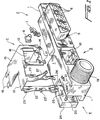
- Figure 1 is a perspective view of a connector constructed in accordance with the principles of a preferred embodiment of the invention.
- Figure 2 is a perspective view of a connector constructed in accordance with the principles of a second preferred embodiment of the invention.
- Figure 3 is a cross-sectional side view of the connector shown in Figure 2.
- Figure 4 is a front view of the outer contact for the BNC portion of the connector of Figure 2.
- the connector of the first preferred embodiment includes a combined housing 1 having a D-sub section 2, a modular jack section 3, and a BNC section 4.
- the shared housing 1 is preferably molded from a suitable plastic, in which case the housing can easily be made in a variety of configurations for different connector types, the illustrated types being typical of a network interface card.
- the D-sub section 2 of the first preferred embodiment is conventional in nature, except that its housing is integral with the housing of the modular jack section. Included in this section are a conventional metal shield 5 which surrounds a D-shaped front portion including apertures 6 for receiving correspondingly shaped male or female connector contacts (not shown). Unlike the standard D-sub connector, however, the illustrated D-sub connector section 2 requires only a single board lock 7 for securing the D-sub section on the board. An optional connecting pin 9 for electrically connecting shield 5 with the board lock to provide a ground path therethrough when the board lock is secured to the circuit board may also be provided. Those skilled in the art will recognize that the configuration of the rear portion of the connector section, which is arranged to permit connections between the contacts and the board, is conventional and may be varied according to the specific requirements of the type of D-sub being implemented.
- the modular jack section 3 of the connector has a shape identical to the shape of the standard modular jack connector, except that the housing is integrally molded with connector section 2 and 4.
- the jack receiving aperture 10 in the front of the section, and all internal components (not shown) are identical to those found in conventional jack connectors.
- the principal departure from conventional connectors in this section of the combination connector is that, instead of a conventional stamped and formed shield case which fits over at least four sides of the housing, a modified shield 11, which is also preferably stamped and formed, is provided which is shaped to take into account the fact that only three walls of the section are exposed, and which includes an extension 12 for providing, as will be explained below, grounding in the BNC section 4 of the combination connector.
- the portion of shield 11 which covers exposed walls of the modular jack section 3 includes a planar front portion 13 having a cutout 14 corresponding to the aperture 10 in the modular jack, a top portion 15 extending transversely to the front portion 13 which completely covers the top of modular jack section 3, and a single side portion 16 extending transversely to both the top and front portions of section 3, portion 16 being designed to fit between the D-sub connector section 2 and the modular jack section 3.
- pairs of tabs 17 and 18 which can be bent respectively over the bottom and back of the modular jack section to secure the shield on the housing, although those skilled in the art will appreciate that numerous other arrangements for securing the shield on the housing may also be utilized.
- Shield 11 includes a lateral extension 12, as noted above, which covers the top of the main body of BNC connector section 4 for use as a ground connection in case the BNC connector is filtered.
- the filtering arrangement and other aspects of the BNC section, including the shape of a threaded front mating portion 19, are similar to those disclosed in U.S. Patent Application 08/075,876, and includes filter components, e.g., chip capacitors 20 inserted into slots (not shown) which extend parallel to the direction of the BNC contact and which communicate with vertical passages 21 formed in the connector housing.
- Lateral extension 12 of shield 11 includes further extensions 22 which fit into passages 21 and which include upper tines 23 and lower tines 23' arranged to extend into corresponding ones of the chip capacitor slots when extensions 13 are inserted into passages 21, thereby biasing any chip capacitors present in the slots against a parallelepiped shaped rear portion 24 of a metal BNC contact 25 of the type disclosed in the above-mentioned application S.N. 08/075,876.
- the shield 11 also advantageously includes an integral board lock in the form of bifurcated portions 26 at the distal ends of extensions 22. Bifurcation of the ends of extensions results in the formation of fingers which can bend inwardly upon passage through a hole in a circuit board and then outwardly when the hole is cleared to lock the connector on the board in the manner of conventional board locks, but without the need for an extra piece or assembly step.
- a panel-engaging extension 27 similar to those described in copending patent application Serial Number 08/075,876 for providing a ground path from the shield 11 to a panel on the circuit card or device to which the connector is mounted.
- a combination connector according to a second preferred embodiment of the invention includes a modular jack section 103 having a shape identical to the shape of a standard modular jack connector, except that the housing is integrally molded with BNC connector section 104. Except as noted below, all components of both the modular jack section and the BNC section are standard, and thus only those features which represent improvements over conventional connectors of the subject types, or which are necessary for an understanding of the invention, are illustrated.
- the body of the modular jack portion 103 of the combination connector illustrated in Figures 2 and 3 is identical to the modular jack disclosed in copending U.S. Patent Application S.N. 08/043,544, and includes a jack receiving aperture 105, openings 106 at the top of aperture 105, and grooves 107 in the top surface of the jack section for receiving contacts 98 and 99 having a generally standard configuration.
- the contacts are positioned such that, when filter elements are place in the openings, electrodes on the filter elements engage the contacts.
- the combination connector of this embodiment includes a single stamped and formed shield member 109 which includes a front wall 110 having a cutout or opening 111 corresponding in shape to the shape of the jack-receiving aperture 105, a top 112, a side wall 113, and an extension 114 of the top which covers the top surface of the BNC section 104 of the combination connector. Also part of the single shield member 109 are side walls 115 and 116 for respectively shielding remaining exposed sides of the modular jack and BNC sections of the connector. In addition, the shield member may include extensions (not shown) at the rear of the respective connector sections. As is apparent in Figure 2, front wall 110, top portions 112,114, and side walls 113, 115, and 116 are all mutually perpendicular.
- the top of the shield member also includes, in the illustrated embodiment, downwardly extending tines 117 for engaging, in the manner disclosed in copending application S.N. 08/043,544, ground electrodes on any filter elements which have been inserted into openings 108.
- the shield member may be secured to the housing by tabs 118 which can be bent at a ninety degree angle to engage the bottom of the connector once the shield has been positioned on the housing, although those skilled in the art will appreciate that numerous alternative means may be sued to secure the shield on the connector.
- the BNC section 104 of the combination connector includes two unique features which may also be used in stand-alone BNC connectors:
- the first of these particularly unique and advantageous features is that all insulating portions of the BNC section, including the conventionally separate insulators 161 and 162, respectively, which surround the inner and outer coaxial contact, are molded in a single mold.
- the entire connector, including both the jack and BNC portions may be produced in a single step, without even the need for separate molding and assembly of the inner insulator.
- This feature is accomplished, as is best shown in Figure 3, by forming a single front insulating portion 119 of BNC section 103 with an annular groove 120 for accommodating the outer contact 121 and which separates insulators 140 and 141, and a cylindrical bore 122 in the portion of the insulator which lies within the groove 120 for accommodating the inner contact 123, and providing at the rear of the groove 120 which accommodates the outer contact 121 a through-hole 124.
- the outer contact 121 can thus be connected to the circuit board (not shown) on which the combination connector is mounted by providing an extension or a discrete contact pin 125 secured in bore 126 in the outer contact, and which is inserted through through-hole 124 as outer contact 121 is positioned from the front of the connector during assembly in the annular groove.
- pin 125 is normally bent so that it extends downward past the rear of the BNC section to engage the circuit board, although those skilled in the art will appreciate that the principles of the invention will also apply to a vertical, as opposed to right angle, connector configuration (particularly in the case of a stand-alone BNC connector), in which case pin 125 would not be bent.
- the inner contact also includes an extension which is bent downward after insertion of the inner contact to engage an appropriate lead on the circuit board.
- Filter capabilities are provided, according to a second unique and particularly advantageous feature of this embodiment, by an especially simple structure involving the inclusion of flanges 130 on the outer contact 121, as shown in Figures 2 and 4.
- Flanges 130 have an upwardly facing planar surface 131 for contacting the live electrode 132 of a chip capacitor or other filter element 133 placed into openings 136.
- the ground connection provided by the filter elements can then be completed simply by causing downwardly extending tines 134 cut out of the shield member 109 to engage a ground electrode 135 on the filter element, the tine biasing the filter element against the planar surface of outer contact 121 contact.
- shield member 109 of this embodiment also included as part of shield member 109 of this embodiment is a panel-engaging tongue 137 for directly grounding the shield member to a panel provided on the interface card, in the manner disclosed in copending application S.N. 08/075,876.
- a separate board lock 138 is illustrated for this embodiment, it would of course also be possible to modify the shield casing to include a board lock in the manner similar to that of the first embodiment.
- the modular jack, BNC, and, if applicable, multiple pin parallel-type connector contacts need to be inserted into the respective connector sections, followed by insertion of any desired filter chips, and placement of the combined shield casing over the plastic insulative one-piece molded housing.
- just two basic assembly steps three if filtering is desired, are necessary to complete assembly of a fully functional combination connector.
Landscapes
- Details Of Connecting Devices For Male And Female Coupling (AREA)
- Coupling Device And Connection With Printed Circuit (AREA)
Applications Claiming Priority (4)
| Application Number | Priority Date | Filing Date | Title |
|---|---|---|---|
| US219161 | 1994-03-28 | ||
| US08/219,161 US5401192A (en) | 1994-03-28 | 1994-03-28 | Combination connector |
| US252425 | 1994-06-01 | ||
| US08/252,425 US5407366A (en) | 1994-03-28 | 1994-06-01 | Combination connector |
Publications (2)
| Publication Number | Publication Date |
|---|---|
| EP0675570A2 true EP0675570A2 (de) | 1995-10-04 |
| EP0675570A3 EP0675570A3 (de) | 1998-03-04 |
Family
ID=22818134
Family Applications (1)
| Application Number | Title | Priority Date | Filing Date |
|---|---|---|---|
| EP95400679A Withdrawn EP0675570A3 (de) | 1994-03-28 | 1995-03-28 | Kombinationssteckverbinder |
Country Status (3)
| Country | Link |
|---|---|
| US (2) | US5401192A (de) |
| EP (1) | EP0675570A3 (de) |
| CA (1) | CA2144704A1 (de) |
Cited By (2)
| Publication number | Priority date | Publication date | Assignee | Title |
|---|---|---|---|---|
| WO2006020677A3 (en) * | 2004-08-10 | 2006-04-20 | Nvidia Corp | Vga connector with integral filter |
| WO2006079555A1 (de) * | 2005-01-28 | 2006-08-03 | Amphenol-Tuchel Electronics Gmbh | Steckverbinder |
Families Citing this family (42)
| Publication number | Priority date | Publication date | Assignee | Title |
|---|---|---|---|---|
| US5613880A (en) * | 1995-07-28 | 1997-03-25 | Wang; Tsan-Chi | Dual-plug BNC connector |
| JPH0963716A (ja) * | 1995-08-25 | 1997-03-07 | Hirose Electric Co Ltd | 携帯電話機用複合コネクタ |
| US5643008A (en) * | 1995-09-06 | 1997-07-01 | Hon Hai Precision Ind. Co., Ltd. | System for arrangement of different input/output connectors |
| KR0155639B1 (ko) * | 1995-10-04 | 1998-11-16 | 김광호 | 비엔씨/디-서브 자동선택회로 |
| USD377336S (en) * | 1995-12-08 | 1997-01-14 | Hon Hai Precision Ind. Co., Ltd. | Stacked connector |
| US5695362A (en) * | 1996-09-27 | 1997-12-09 | The Whitaker Corporation | Hybrid grounded and stacked connector assembly with audio jacks |
| US5755592A (en) * | 1996-09-27 | 1998-05-26 | The Whitaker Corporation | Combined ground strap and board lock for electrical connector assembly |
| US6033263A (en) * | 1996-10-15 | 2000-03-07 | The Whitaker Corporation | Electrically connector with capacitive coupling |
| US5984725A (en) * | 1997-04-30 | 1999-11-16 | Berg Technology, Inc. | Filtered universal serial bus |
| US6206724B1 (en) * | 1997-06-06 | 2001-03-27 | Tommy Y. Leung | Combined connector for ethernet and modem cables |
| USD416861S (en) * | 1997-06-14 | 1999-11-23 | Hon Hai Precision Ind. Co., Ltd. | Electrical connector |
| US6109971A (en) * | 1997-07-02 | 2000-08-29 | Adaptec, Inc. | High-speed serial data cable with improved electromagnetic performance |
| TW347156U (en) * | 1997-08-13 | 1998-12-01 | Molex Taiwan Ltd | Mixing-type universal connector |
| US5975958A (en) * | 1997-10-14 | 1999-11-02 | The Whitaker Corporation | Capactive coupling adapter for an electrical connector |
| US6036544A (en) * | 1998-01-16 | 2000-03-14 | Molex Incorporated | Coupled electrical connector assembly |
| US6200161B1 (en) | 1998-04-03 | 2001-03-13 | The Whitaker Corporation | Stacked electrical connector |
| JP3649584B2 (ja) | 1998-05-06 | 2005-05-18 | アルプス電気株式会社 | 高周波電子機器 |
| USD409572S (en) * | 1998-05-13 | 1999-05-11 | Focus Enhancements, Inc. | Electrical connector |
| DE19840413C1 (de) | 1998-09-04 | 2000-02-03 | Harting Kgaa | Abgeschirmter elektrischer Steckverbinder |
| USD420645S (en) * | 1998-09-22 | 2000-02-15 | Hon Hai Precision Ind. Co., Ltd. | Electrical connector |
| USD420979S (en) * | 1998-10-13 | 2000-02-22 | Hon Hai Precision Ind. Co., Ltd. | Electrical connector |
| TW405762U (en) | 1998-11-11 | 2000-09-11 | Molex Inc | Connector |
| TW446215U (en) * | 1999-07-06 | 2001-07-11 | Hon Hai Prec Ind Co Ltd | Electrical connector combination |
| US6394846B1 (en) | 1999-08-06 | 2002-05-28 | Fci Americas Technology, Inc. | Electrical connector with separate receptacles using common filter |
| US6422901B1 (en) | 1999-12-06 | 2002-07-23 | Fci Americas Technology, Inc. | Surface mount device and use thereof |
| US6296525B1 (en) | 2000-01-07 | 2001-10-02 | J. D'addario & Company, Inc. | Electrical plug and jack connectors |
| US6533617B1 (en) | 2000-01-07 | 2003-03-18 | J. D'addario & Company, Inc. | Electrical plug connectors |
| US6790052B2 (en) | 2000-02-14 | 2004-09-14 | Molex Incorporated | Circuit board straddle mounted connector |
| US6746279B1 (en) * | 2000-11-07 | 2004-06-08 | Ixos Limited | Power distribution system |
| US6632105B2 (en) * | 2001-08-17 | 2003-10-14 | Hon Hai Precision Ind. Co., Ltd. | Input/output connector having firmly assembled insulative housing and shell |
| JP3936859B2 (ja) * | 2001-11-09 | 2007-06-27 | 日本圧着端子製造株式会社 | 同軸コネクタ及びその製造方法、並びに当該同軸コネクタを用いた電磁波漏洩抑制方法 |
| US6953371B2 (en) * | 2002-04-30 | 2005-10-11 | Corning Gilbert Inc. | Apparatus for electrically coupling a linear conductor to a surface conductor and related method |
| US20050153598A1 (en) * | 2004-01-14 | 2005-07-14 | Meister Douglas L. | Connector assembly |
| US7037840B2 (en) * | 2004-01-26 | 2006-05-02 | Micron Technology, Inc. | Methods of forming planarized surfaces over semiconductor substrates |
| US6981892B1 (en) | 2004-05-28 | 2006-01-03 | Kostelnik Bradley D | Combination telephony and cable jack interface |
| JP2007005234A (ja) * | 2005-06-27 | 2007-01-11 | Hirose Electric Co Ltd | シールドケース付電気コネクタ |
| US7147517B1 (en) | 2005-09-22 | 2006-12-12 | Aines Manufacturing Corp. | Line tone adapter for a cable test system |
| US7901221B1 (en) * | 2009-01-09 | 2011-03-08 | Amazon Technologies, Inc. | Universal serial bus ground clip |
| US8192209B1 (en) | 2009-01-09 | 2012-06-05 | Amazon Technologies, Inc. | Surface mount clip for routing and grounding cables |
| US8011950B2 (en) * | 2009-02-18 | 2011-09-06 | Cinch Connectors, Inc. | Electrical connector |
| CN103545669A (zh) * | 2012-07-13 | 2014-01-29 | 鸿富锦精密工业(深圳)有限公司 | Usb连接器 |
| GB2533354B (en) * | 2014-12-17 | 2017-09-13 | Etl Systems Ltd | Connector assembly and related methods and assemblies |
Family Cites Families (41)
| Publication number | Priority date | Publication date | Assignee | Title |
|---|---|---|---|---|
| US3879103A (en) * | 1970-12-07 | 1975-04-22 | Tektronix Inc | Coaxial cable connector for circuit board |
| US3932020A (en) * | 1974-03-29 | 1976-01-13 | The United States Of America As Represented By The Secretary Of The Army | Electrical connectors |
| US3980382A (en) * | 1974-06-03 | 1976-09-14 | Raychem Corporation | Matched impedance coaxial cable to printed circuit board terminator |
| JPS5386387A (en) * | 1976-12-28 | 1978-07-29 | Haruyuki Fujii | Angling rods and method for producing same |
| US4412717A (en) * | 1982-06-21 | 1983-11-01 | Amp Incorporated | Coaxial connector plug |
| US4500159A (en) * | 1983-08-31 | 1985-02-19 | Allied Corporation | Filter electrical connector |
| US4602842A (en) * | 1984-12-03 | 1986-07-29 | Cts Corporation | Electrical connector receptacle |
| US4695105A (en) * | 1984-12-20 | 1987-09-22 | Amp Incorporated | Filtered electrical receptacle |
| US4618207A (en) * | 1985-06-05 | 1986-10-21 | Molex Incorporated | Two piece modular receptacle |
| US4629266A (en) * | 1985-06-13 | 1986-12-16 | Amp Incorporated | Electrical device, such as an electrical connector receptacle, for surface mounting on a circuit board |
| EP0211193A1 (de) * | 1985-07-10 | 1987-02-25 | Siemens Aktiengesellschaft | Vorrichtung zur Verbindung der Schirmung mehrpoliger Stecker mit der Erdpotentialschicht eines Baugruppenträgers |
| US4726638A (en) * | 1985-07-26 | 1988-02-23 | Amp Incorporated | Transient suppression assembly |
| US4690479A (en) * | 1985-10-10 | 1987-09-01 | Amp Incorporated | Filtered electrical header assembly |
| US4666231A (en) * | 1986-06-26 | 1987-05-19 | Amp Incorporated | Switching coaxial connector |
| US4695115A (en) * | 1986-08-29 | 1987-09-22 | Corcom, Inc. | Telephone connector with bypass capacitor |
| US4804332A (en) * | 1986-12-24 | 1989-02-14 | Amp Incorporated | Filtered electrical device and method for making same |
| US4772224A (en) * | 1987-09-02 | 1988-09-20 | Corcom, Inc. | Modular electrical connector |
| US4795352A (en) * | 1988-02-01 | 1989-01-03 | Amp Incorporated | Microcoaxial connector family |
| US4842529A (en) * | 1988-03-31 | 1989-06-27 | Amp Incorporated | Connector with two-piece ground strap |
| US5143868A (en) * | 1988-04-08 | 1992-09-01 | Panduit Corp. | Communication box assembly |
| US4850902A (en) * | 1988-04-11 | 1989-07-25 | Amp Incorporated | Electrical connector having improved characteristics for retaining leads to the connector housing and method of making the electrical connector |
| US4799901A (en) * | 1988-06-30 | 1989-01-24 | Pirc Douglas J | Adapter having transient suppression protection |
| JPH0517821Y2 (de) * | 1988-07-27 | 1993-05-12 | ||
| HU205219B (en) * | 1989-01-23 | 1992-03-30 | Kontakta Villamosszerelesi Val | Module system receptacle series |
| US4884982A (en) * | 1989-04-03 | 1989-12-05 | Amp Incorporated | Capacitive coupled connector |
| US5073123A (en) * | 1989-05-19 | 1991-12-17 | Amp Incorporated | Self terminating tap connector |
| US5106325A (en) * | 1990-01-19 | 1992-04-21 | Leviton Manufacturing Co. Inc. | Modular higher density communications coupling system |
| EP0461454B1 (de) * | 1990-06-11 | 1995-04-19 | Siemens Aktiengesellschaft | Verteilereinrichtung |
| US5057041A (en) * | 1990-06-29 | 1991-10-15 | Foxconn International | User configurable integrated electrical connector assembly |
| US5062811A (en) * | 1990-10-30 | 1991-11-05 | Amp Incorporated | Capacitive coupled connector for PCB grounding |
| US5083945A (en) * | 1991-02-01 | 1992-01-28 | Molex Incorporated | Shielded electrical connector assembly |
| US5102354A (en) * | 1991-03-02 | 1992-04-07 | Molex Incorporated | Filter connector |
| US5108300A (en) * | 1991-04-16 | 1992-04-28 | Amp Incorporated | Electrical connector with interlocked components |
| US5207597A (en) * | 1991-06-21 | 1993-05-04 | Amp Incorporated | Shielded connector with dual cantilever panel grounding beam |
| US5125854A (en) * | 1991-07-16 | 1992-06-30 | Molex Incorporated | Modular electrical connector |
| US5192228A (en) * | 1991-09-16 | 1993-03-09 | Amp Inc. | Shielded surface mount electrical connector with integral barbed board lock |
| US5145412A (en) * | 1991-10-18 | 1992-09-08 | Foxconn International, Inc. | Filter connector |
| US5167536A (en) * | 1992-02-20 | 1992-12-01 | Wang Tsan Chi | Capactive coupled BNC type connector |
| US5288246A (en) * | 1993-04-06 | 1994-02-22 | The Whitaker Corporation | Electrical connector for back panel mounting |
| US5397250A (en) * | 1993-04-06 | 1995-03-14 | Amphenol Corporation | Modular jack with filter |
| US5326280A (en) * | 1993-06-14 | 1994-07-05 | Amphenol Corporation | Coaxial connector with integral decoupling unit |
-
1994
- 1994-03-28 US US08/219,161 patent/US5401192A/en not_active Expired - Fee Related
- 1994-06-01 US US08/252,425 patent/US5407366A/en not_active Expired - Fee Related
-
1995
- 1995-03-15 CA CA002144704A patent/CA2144704A1/en not_active Abandoned
- 1995-03-28 EP EP95400679A patent/EP0675570A3/de not_active Withdrawn
Cited By (3)
| Publication number | Priority date | Publication date | Assignee | Title |
|---|---|---|---|---|
| WO2006020677A3 (en) * | 2004-08-10 | 2006-04-20 | Nvidia Corp | Vga connector with integral filter |
| WO2006079555A1 (de) * | 2005-01-28 | 2006-08-03 | Amphenol-Tuchel Electronics Gmbh | Steckverbinder |
| US7597562B2 (en) | 2005-01-28 | 2009-10-06 | Amphenol-Tuchel Electronics Gmbh | Plug-in connector |
Also Published As
| Publication number | Publication date |
|---|---|
| US5407366A (en) | 1995-04-18 |
| CA2144704A1 (en) | 1995-09-29 |
| US5401192A (en) | 1995-03-28 |
| EP0675570A3 (de) | 1998-03-04 |
Similar Documents
| Publication | Publication Date | Title |
|---|---|---|
| US5407366A (en) | Combination connector | |
| US5601451A (en) | Combination connector | |
| CA2120536C (en) | Modular jack with filter | |
| US6346009B1 (en) | Shielded multiple electrical connector assembly | |
| US5125854A (en) | Modular electrical connector | |
| USRE35159E (en) | Electrical connectors | |
| US5344342A (en) | Filtered VGA connector | |
| US6457993B1 (en) | Modular jack with LED | |
| US6923687B2 (en) | Audio jack having improved contacts | |
| EP1066663B1 (de) | Electrischer modularstecker mit niedrigem profil und damit ausgerüstete kommunikationskaste | |
| US5975954A (en) | Universal serial bus receptacle electric connector | |
| US20020048992A1 (en) | Vertically stacked usb connector | |
| US6234834B1 (en) | Stacked electrical connector assembly | |
| US4863393A (en) | Modular jack assembly with improved bridging arrangement | |
| EP0543300B1 (de) | Abgeschirmter schwimmender elektrischer Verbinder | |
| US6918791B2 (en) | Electrical connector having a reliable internal circuit board | |
| US7052329B2 (en) | Electrical connector with an internal modem | |
| US6739915B1 (en) | Electrical connector with rear retention mechanism of outer shell | |
| WO1998013904A1 (en) | Hybrid grounded and stacked connector assembly with audio jacks | |
| EP1089397B1 (de) | Elektrischer Verbinder mit Haltemitteln zur lösbaren Fixierung einer Bauelementenpackung | |
| US6641440B1 (en) | Electrical connector with power module | |
| US6089916A (en) | Cable assembly connector | |
| US6997754B2 (en) | Electrical connector assembly with low crosstalk | |
| US5827092A (en) | Filtered electrical adapter and connector | |
| JP2553012Y2 (ja) | 電気コネクタ |
Legal Events
| Date | Code | Title | Description |
|---|---|---|---|
| PUAI | Public reference made under article 153(3) epc to a published international application that has entered the european phase |
Free format text: ORIGINAL CODE: 0009012 |
|
| AK | Designated contracting states |
Kind code of ref document: A2 Designated state(s): DE FR GB |
|
| PUAL | Search report despatched |
Free format text: ORIGINAL CODE: 0009013 |
|
| AK | Designated contracting states |
Kind code of ref document: A3 Designated state(s): DE FR GB |
|
| STAA | Information on the status of an ep patent application or granted ep patent |
Free format text: STATUS: THE APPLICATION IS DEEMED TO BE WITHDRAWN |
|
| 18D | Application deemed to be withdrawn |
Effective date: 19980905 |