EP0675638A2 - Farbbildverarbeitungsverfahren und dieses benutzendes Gerät - Google Patents
Farbbildverarbeitungsverfahren und dieses benutzendes Gerät Download PDFInfo
- Publication number
- EP0675638A2 EP0675638A2 EP95302144A EP95302144A EP0675638A2 EP 0675638 A2 EP0675638 A2 EP 0675638A2 EP 95302144 A EP95302144 A EP 95302144A EP 95302144 A EP95302144 A EP 95302144A EP 0675638 A2 EP0675638 A2 EP 0675638A2
- Authority
- EP
- European Patent Office
- Prior art keywords
- color
- conversion
- signal
- conversion function
- color image
- Prior art date
- Legal status (The legal status is an assumption and is not a legal conclusion. Google has not performed a legal analysis and makes no representation as to the accuracy of the status listed.)
- Ceased
Links
Images


Classifications
-
- H—ELECTRICITY
- H04—ELECTRIC COMMUNICATION TECHNIQUE
- H04N—PICTORIAL COMMUNICATION, e.g. TELEVISION
- H04N1/00—Scanning, transmission or reproduction of documents or the like, e.g. facsimile transmission; Details thereof
- H04N1/46—Colour picture communication systems
- H04N1/56—Processing of colour picture signals
- H04N1/60—Colour correction or control
- H04N1/6058—Reduction of colour to a range of reproducible colours, e.g. to ink- reproducible colour gamut
Definitions
- This invention relates to a color image processing method and an apparatus utilizing the same and, more particularly, to a color image processing method and an apparatus utilizing the same for obtaining identical color reproduction characteristics between apparatuses, e.g., a color image input device, a display device, and an output device, having different color reproduction characteristics from each other.
- apparatuses e.g., a color image input device, a display device, and an output device, having different color reproduction characteristics from each other.
- a CRT color monitor reproduces an image by using additive color mixing in which luminance signals, for each RGB phosphors, are changed, whereas a color printer reproduces an image by using subtractive color mixing in which ink density of each YMCK color is changed. Therefore, when an image displayed on such a CRT color monitor is reproduced by an ink-jet type color printer, for instance, the color displayed on the monitor and the color outputted by the color printer are quite different from each other in most cases because of the different color reproduction characteristics of these two devices.
- the printer may outputs an image deteriorated and having less tones, which has been a conventional problem.
- Fig. 12 there is one shown in Fig. 12.
- reference numeral 71 denotes a first conversion function for converting a first color signal representing a color on a monitor into a standard color signal
- reference numeral 72 denotes data showing color reproduction characteristics of the monitor analyzed in advance. Coefficients of the first conversion function are determined based on the data.
- a standard color space signal 73 is expressed in the XYZ color system defined by the CIE (Comission Internationale de l'Eclairage) in 1931.
- reference numeral 74 denotes a second conversion function for converting the standard color space signal 73 expressed by the XYZ color system into a second color signal for printer output
- reference numeral 75 denotes data showing color reproduction characteristics of the printer. The second conversion function is determined in accordance with the data.
- Fig. 12 the idea illustrated in Fig. 12 is to convert an image on the monitor into an image outputted by the printer having an identical color reproduction characteristics to those of the monitor by using the two conversion functions via the standard color space signal which is expressed in the XYZ color system.
- a color signal is converted twice by operating the two conversion functions, thus it requires considerable processing time. It is possible to make another function by synthesizing the two functions in advance, then perform conversion of the color signal. However, when characteristics of a device to be used are changed or a conversion result is to be outputted to another device having different output characteristics, the synthesized function must be generated each time, which makes an operational sequence of the image processing complicated.
- the second conversion function includes a process to adjust differences between the color gamuts of devices, it is difficult to change only the part of the adjusting process, or select the adjusting process out of plural kinds of processes.
- a color image processing apparatus comprising: memory means for storing a first conversion function for converting a first color image signal into a signal in a predetermined color space and a second conversion function for converting the signal in the predetermined color space into a second color image signal, and a third conversion function used for performing a color signal conversion in consideration with color gamuts of units, which output the first and the second color image signals, in the predetermined color space; first synthesize means for obtaining a fourth conversion function by synthesizing the third conversion function and at least the first or the second conversion functions; and first conversion means for converting the first color image signal into the second color image signal by operating the fourth conversion function obtained by the first synthesize means.
- the foregoing object is attained by providing a color image processing method, based on a first conversion function used for converting a first color image signal into a signal in a predetermined color space, a second conversion function used for converting the signal in the predetermined color space into a second color image signal, and a third conversion function used for performing color signal conversion in consideration with color gamuts, in the predetermined color space, of units which output the first and the second color image signals, where all of the functions are stored in a storage medium, comprising: synthesize step of obtaining a fourth conversion function by synthesizing the third conversion function and at least the first or the second conversion functions; and conversion step of converting the first color image signal into the second color image signal by operating the fourth conversion function obtained in the synthesize step.
- a fourth conversion function is obtained by synthesizing the third conversion function and at least the first or the second conversion functions, and the first color image signal is converted into the second color image signal by operating the fourth conversion function.
- the invention is particularly advantageous since the adjustment of the differences between the color gamut including the first color image signal and the color gamut including the second color image signal is performed by using the third conversion function, the adjustment can be easily and more flexibly performed only by changing, adding, or selecting the third conversion function. Further, selection designating processes regarding color characteristics of input image signal, a method of color matching process, and color characteristics of an output image signal are performed independently, thus it is easy to select, add, and change each process.
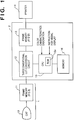
- Fig. 1 is a block diagram illustrating a configuration of an image processing system as a typical embodiment of the present invention.
- This system comprises a display 1, a color conversion unit 2, and an electrophotographic type color printer 14.
- An image displayed on a CRT monitor 10 of the display 1 is outputted to the color printer 14 via the color conversion unit 2.
- reference numeral 10 denotes the CRT color monitor; 11, a frame memory for storing color image signals (RGB signals) to be displayed on the CRT color monitor 10; 12, a three dimensional look-up table (LUT) conversion circuit for performing color signal conversion; 13, a frame memory for storing converted R'G'B' signals; 15, a CPU; 15a a ROM for storing a control program to be executed by the CPU 15; and 16, a memory for storing a plurality of color signal conversion functions or conversion coefficients for converting color signals.
- LUT three dimensional look-up table
- the CPU 15 executes the program stored in the ROM 15a, it reads the plurality of color signal conversion functions stored in the memory 16, and executes the conversion processing, e.g., by controlling, a RAM (not shown) used as a work area.
- a RAM not shown
- the frame memory 13 transmits a R'G'B' signal obtained by the three dimensional LUT conversion circuit 12 to the color printer 14 which outputs a visual image. Further, the CPU 15 reads the plurality of color signal conversion functions or conversion coefficients stored in the memory 16, then sets the read functions or coefficients to the three dimensional LUT conversion circuit 12, and controls execution of signal conversion.
- the CPU 15 comprises a designating unit (not shown) capable of designating color characteristics and inputting a visual display instruction (to output an image displayed on the display 1 to the color printer 14) from the outside.
- the designating unit may be, for example, a keyboard or a numeric keyboard, or have a configuration capable of connecting to a floppy disk drive which can read information in a floppy so that a large amount of color characteristic information (e.g., conversion coefficients corresponding to a plurality of devices), designation, and instructions can be inputted at a time.
- the memory 16 stores color characteristics of plural kinds of displays and color printers which may be used as color signal conversion functions or conversion coefficients
- the selective input of the specific number, symbol and character string from the designating unit enables the apparatus to designate the color characteristics.
- the designation of color characteristics in the following explanation is performed by using the above-mentioned approach.
- Fig. 2 is a block diagram illustrating a configuration of the three dimensional LUT conversion circuit 12.
- an input RGB signal is divided into upper bit(s) data 61 and lower bit(s) data 62, and a table memory 63 stores output signals corresponding only to the upper bit(s) data, and the output value 64 corresponding to the upper bit(s) data 61 is inputted into an interpolation circuit 65.
- the lower bit(s) data 62 is inputted into the interpolation circuit 65 where the output value 64 is linearly interpolated by using the lower bit(s) data 62 to obtain an output signal 66.
- only a R' signal is shown as the output signal 66, however, G' and B' signals are also outputted after being applied with the same process as described above, needless to say.
- the signal conversion can be performed by re-writing contents of the table memory 63 when not only matrix conversion but also an arbitrary conversion function are used.
- the content of the table memory 63 is determined in an operational sequence which will be described later.
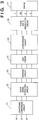
- Fig. 3 is a block diagram illustrating a detailed configuration of the color printer 14.
- the color printer 14 includes a logarithmic conversion circuit 21, a black signal extracting circuit 22, a masking circuit 23, a UCR circuit 24, a ⁇ -conversion circuit 25, a pulse width modulation circuit 26, and a printer engine 27.
- the R'G'B' signal When a R'G'B' signal is inputted from the frame memory 13 to the color printer 14, the R'G'B' signal is converted into a YMC signal at the logarithmic conversion circuit 21.
- the YMC signal is converted into a YMCK signal after being applied with well-known color correction processes at the black signal extracting circuit 22, the masking circuit 23, the UCR circuit 24, and the ⁇ -conversion circuit 25.
- Each color component of the YMCK signal is applied with the pulse width modulation by the pulse width modulation circuit 26, and eventually becomes a pulse signal which triggers emission of a laser beam for electrophotographically forming an image on an electrostatic drum.
- the pulse signal is transmitted to the printer engine 27 which drives a semiconductor laser (not shown), to emit the laser beam.
- the laser beam is controlled by a polygon mirror rotating at high speed so as to scan the electrostatic drum (not shown), thereby a latent image is formed on it.
- the latent image is developed to a visual image with toner of four colors, namely, Y, M, C, and K, then transferred to a print sheet and fixed. Then, the color printer 14 discharges the print sheet.
- Fig. 4 is the flowchart briefly showing a brief color conversion processing executed by the CPU 15.
- the color conversion processing converts a first color image signal, stored in the frame memory 11, which is a display color signal of the CRT color monitor 10 into a third color image signal which is an output color signal to the printer 14 used for permanent visible representation, and output it.
- a first conversion function for converting the first color image signal into a standard color space signal a second conversion function for converting the standard color space signal into a second color image signal
- a third conversion function for converting the standard color space signal which is converted by the first conversion function, by color matching process based on a color gamut of an output device are selected in accordance with a processing which will be described later.
- the first to third conversion functions are synthesized, and the first color image signal is converted into the third color image signal by using the synthesized new conversion function.
- the color signal at the display 1 side is called “the first color signal”, and the color signal at the color printer 14 side is called as “the record color signal”, hereinafter.
- the CPU 15 selects characteristics of the first color signal, in accordance with an input designation, which is at the image input side stored in advance in a predetermined area, for instance, of the memory 16. This process corresponds to designation of color reproduction characteristics of the CRT monitor 10 in which an input image data is displayed, and this designation input is performed by a user or a maintenance engineer, for instance, by designating name of manufacturer and supplier, or of type of the device in a predetermined operational sequence.
- the CPU 15 selects characteristics of the second color signal which is at the image output side stored in advance in a predetermined area, for instance, of the memory 16. This process corresponds to the designation of the color reproduction characteristics of the printer 14, and, similarly to step S1, the designation is performed by designating name of a manufacturer and a supplier, or type of the device.
- step S3 there is selected a color matching method including a color space compression processing, based on the selected result, for converting the first color signal stored in the frame memory 11 into a color signal adjusted to a color gamut of the printer 14 which is the output device at the three dimensional LUT conversion circuit 12.
- a color matching method including a color space compression processing, based on the selected result, for converting the first color signal stored in the frame memory 11 into a color signal adjusted to a color gamut of the printer 14 which is the output device at the three dimensional LUT conversion circuit 12.
- the CPU 15 waits until the user inputs a visualized image output instruction at step S4.
- the process moves to step S5, and the CPU 15 which received the instruction fetches the first conversion function from the memory 16 for converting the first color signal at the input side into the standard color space signal in accordance with the color characteristic information selected at step S1.
- the second conversion function for converting the standard color space signal into the second color signal at the output side is fetched from the memory 16 based on the color characteristic information selected at step S2.
- the third conversion function stored in the memory 16 for adjusting the standard color space signal to suit for the color gamut of the printer 14 is fetched based on the method selected at step S3, for instance.
- the first and the second conversion functions selected out of the conversion functions are three dimensional LUT conversion functions, and the LUT data is determined in advance in accordance with the color characteristics of the CRT color monitor 10, the color characteristics of the printer 14, and the definition of the standard color space, and the data values are stored in the memory 16.
- relationship between the input first color signal (R, G, B) and the standard color space signal (L, M, N) is defined by three dimensional functions, F L , F M , F N , as the first conversion functions, selected in the aforesaid process, as follow.
- the relationship between the standard color space signal (L, M, N) and the second color signal (R', G', B') as an output is also defined by three dimensional functions, H R , H G , H B , as the second conversion functions as follow.
- the relationship between the standard color space signal (L, M, N) and the standard color space signal (L', M', N') converted by a color matching process is defined by three dimensional functions, K L , K M , K N , as the third conversion functions as follow.
- step S8 the CPU 15 generates synthesized functions of the first to the third conversion functions selected at the processes of step S5 through step S7.
- step S9 the LUT data based on the synthesized functions are written in the table memory 63 of the three dimensional LUT conversion circuit 12.
- the CPU 15 sequentially generates such the R, G, B signals at step S9. Further, the CPU 15 finds L, M, and N corresponding each generated signal by using the equations (1), then L', M', and N' are found by substituting the obtained L, M, N into the equations (3), then the obtained L', M', N' are substituted into the equations (2) to obtain R', G' and B', finally the obtained values are written in the table memory 63. The aforesaid processes are repeated at step S9.
- step S10 color signals R, G, B to be printed is read out of the frame memory 11 which stores the input color image designated to be printed out. Further, at step S11, the three dimensional LUT 12 performs color signal conversion in accordance with the synthesized functions set at step S9, and the converted color signals R', G', and B' are stored in the frame memory 13. Successively, the color converted color signals R', G', and B' are read from the frame memory 13, then outputted to the printer 14. The printer 14 performs a predetermined color conversion process to convert the input R', G', B' brightness signals into corresponding Y, M, C, and K density signals, then forms an image for permanent visible representation.
- Fig. 6 shows a color gamut of a typical color monitor and that of a typical printer in the CIE 1931 - xy chromaticity diagram shown in Fig. 5.
- reference numeral 501 denotes the color gamut of the typical color monitor and reference numeral 502 denotes the color gamut of the typical printer.
- the input color image signals as color signals inside of the expressible range of the color monitor includes color signals, represented by points 503(A) and 503(B), which can not be reproduced by the printer.
- these signals are printed out as an image without any particular processing, it is predicted that these signals may be printed out as a color on the outermost portion of the color gamut of the printer, as represented by a point 504 in Fig. 6.
- the conversion method is preferably selected by a user.
- the third conversion function shown as the equations (3), that converts the input color signal expressed by the point 503 into the color signal expressed by the point 505.
- the equations (3) converts a standard color space signal by the color matching process, and several functions used as the equations (3) are prepared in advance in consideration with the aforesaid situations. The user can select one set of equations out of these functions.
- the user can select the third functions in consideration with characteristics of an input image or user's preference, thus an image expressed with user's desired colors can be outputted.
- the third conversion function is defined to perform a processing of adjusting the differences between the color gamut of the CRT color monitor 10 and the color gamut of the printer 14 regarding the first color signal. Therefore, it is easy to change, add, and select the processing for the adjustment.
- conversion functions in each processing can be selected anytime, thus a better color conversion can be performed in accordance with characteristics of a signal to be processed. Accordingly, it is possible to provide a color image processing method and apparatus capable of performing better color reproduction.
- an input image signal is converted by using synthesized functions of the first, second and third functions, deterioration of the image caused during the image conversion is reduced, thereby it is possible to obtain a better quality image. Further, according to the embodiment, it is possible to arrange a system capable of effectively adjusting the difference of color gamuts between different devices.
- the color conversion device of the embodiment converts a color signal by using a LUT
- the present invention is not limited to this.
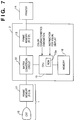
- the device can be arranged by using a matrix conversion circuit 51 in the place of the three dimensional LUT circuit, as shown in Fig. 7.
- a first color signal (R, G, B) and a standard color space signal (L, M, N) are linearly related by a 3 ⁇ 3 matrix
- a second color signal (R', G', B') and the standard color space signal are linearly related by another 3 ⁇ 3 matrix
- the standard color space signal (L, M, N) and the standard color space signal (L', M', N') obtained after the color matching process, are linearly related by another 3 ⁇ 3 matrix
- the color conversion in the embodiment can be performed by executing an application program by the CPU 15, without using a LUT and an operational circuit, thus the apparatus can be constructed to use the application program.
- color conversion from a signal to be displayed on a monitor to another to be printed by a printer taking the differences between the color gamuts of the monitor and the printer into consideration is considered in the embodiment, however, the present invention is not limited to this.
- the embodiment can be applied to difference between color gamuts of a scanner and monitor as shown by 101 in Fig. 8, difference between color gamuts of a scanner and a printer as shown by 102, and difference between color gamuts of a printer and a monitor, and a conversion function considering the scanner as an image signal input device can be the first conversion function, a conversion function considering the printer as an image signal output device can be the second conversion function.
- the present invention is not limited to the apparatus in which a user selects the characteristics of the first color signal and of the second color signal, and the image signal may be added with a header or the like in front of it so that characteristics of the color signal can be automatically selected in accordance with the instruction of the header or the like.
- the synthesized functions are obtained from the first and second conversion functions without considering the third functions described in the previous embodiment, and the first color signal (R, G, B) is converted into the second color signal (R', G', B') in accordance with the synthesized functions.
- the apparatus having the same constitution as described in the previous embodiment is also used in this embodiment, thus the explanation of it is omitted.
- the same processing steps of the color conversion process in this embodiment as those in the previous embodiment are referred by the same step reference numbers, and the explanation of them is also omitted.
- the matrix conversion circuit 51 converts the input RGB signal into a R'G'B' signal by using followinq equation:
- steps S1 and S2 characteristics of a color signal in the display 1 side (RGB signal) and characteristics of a color signal in the color printer 14 side (R'G'B' signal) are selected, respectively. After the selected characteristics are inputted into the CPU 15, the process proceeds to step S33 where the user inputs a visual display instruction to the CPU 15.
- the first conversion function and the second conversion function are fetched from the memory 16 at steps S5 and S6, respectively.
- the process goes back to step S1 or S2 as an error condition has occurred, similarly to the previous embodiment.
- the first and the second conversion functions perform the 3 ⁇ 3 matrix conversion similarly to the equation (4)
- Conversion coefficients of matrices are fixed in advance in accordance with the color gamut of the monitor, that of the printer, and the definition of such a standard color space that is already described with reference to Fig. 5.
- the values of the coefficients are stored in the memory 16.
- step S36 If the conversion coefficients of the equations (5) and (6) are stored in the memory 16 in advance, the CPU 15 reads the coefficients out of the memory 16, then the process proceeds to step S36.
- a new matrix which gives relationship between R', G', B' and R, G, B is generated by synthesizing the equations (5) and (6) as follow. In other words, by performing the following matrix operation, the conversion coefficients of the new matrix are found.
- the conversion coefficients in the equation (7) constructs a function for directly converting the color signal in the input side (RGB signal) into a color signal in the output side (R'G'B' signal).
- the process moves to step S37 where the CPU 15 sets the coefficients (a ij ) of the obtained equation (7) in the matrix conversion circuit 51.
- step S10 the input color image is read from the frame memory 11, and the color conversion processing is performed in accordance with the set coefficients (a ij ) at step S11.
- a conversion function that can define color characteristics of an image input device (a display in this embodiment) and of an image output device (a printer in this embodiment) to be connected to a system in a common standard color space, then determines a conversion function which expresses the input image signal from various devices or the output image signal to various devices by a linear transform representation in the standard color space.
- a conversion matrix for directly connects the image input device and the image output device by using the conversion functions from/to input/output devices.
- the conversion matrix directly connecting the input and the output devices is generated by a simple designating operation to the CPU, and the color conversion can be performed by using the synthesized conversion matrix.
- both the first and the second conversion functions are 3 ⁇ 3 matrix conversion functions
- the synthesized function can be easily obtained by multiplying the two matrices.
- the three dimensional LUT can be used as shown in Fig. 1 instead of the matrix conversion circuit 51 for converting a RGB signal into a R'G'B' signal by a simple operation, as explained in the previous embodiment.
- the relationship between the first color signal R, G, B and the standard color space signal L, M, N is defined by the three dimensional functions F L , F M , F N , as the first conversion functions as the equations (1), and the relationship between the standard color space signal L, M, N and the second color signal R', G', B' as an output is also defined by the three dimensional functions, H R , H G , H B as the equations (2).
- the CPU 15 operates by following the flowchart in Fig. 9, and in the flowchart, synthesized functions of the equations (1) and (2) are generated at step S36, and the results are written in the table memory 63 of the three dimensional LUT conversion circuit 12 at step S37.
- the color conversion is performed by using the LUT, therefore color conversion can be performed without performing complicated operations even if there exists a complicated conversion relationship between the color characteristics of the input and output devices and the standard color space. This results in performing the color conversion at high speed.
- the above-described embodiment relates to a processing between a color display and a color printer, however, the present invention is not limited to this.
- the present invention can be applied to various kinds combinations of image input devices and image output devices, e.g., a case of outputting a color image separated by a flat bed scanner to a color printer, or outputting the same color separated image obtained by the flat bed scanner on the CRT monitor, and the like.
- the present invention can be applied to a system having a "preview” system, for instance, which predicts and reproduces the output result on the monitor without actually printing out an image visualized from the color image data inputted from the image input device.
- a color image signal to be outputted to the output device is converted into an image signal in the standard color space by using a fourth conversion function, then further converted into a color image signal for a preview image display device (such as a monitor) by using a fifth conversion function.
- the color conversion in the above embodiments are performed by using an operational circuit or the LUT, however, the present invention is not limited to this.
- the color conversion can also be performed by executing an application program.
- the aforesaid two embodiments describe the apparatuses constructed so that (1) when the color gamuts of the image signal input device and of the image signal output device differ, the difference is adjusted by using the first to third conversion functions and (2) when difference in the color gamuts do not have to be adjusted in accordance with the user's preference, or color gamuts of the image signal input device and of the image signal output device do not quite differ from each other, thus only the color characteristics of the two devices have to be considered, the color characteristics of the image input device is converted into the color characteristics of the image output device by using the first and the second conversion functions.
- the apparatus can be constructed as follow.
- the apparatus may be provided with two conversion modes, one of which is for performing the color conversion by using the first to third conversion functions, which corresponds to the aforesaid case (1), and the other is for performing the color conversion by using the first and second conversion functions, which corresponds to the aforesaid case (2) depending upon the color gamuts of the image input/output devices to be used and the user's preference, and the two modes can be changed over.
- the change over of the modes can be performed by constructing the apparatus so that the user can designate one of the conversion modes, as shown in Fig. 11.
- the present invention can be applied to a system constituted by a plurality of devices, or to an apparatus comprising a single device. Furthermore, the invention is applicable also to a case where the object of the invention is attained by supplying a program to a system or apparatus.
Landscapes
- Engineering & Computer Science (AREA)
- Multimedia (AREA)
- Signal Processing (AREA)
- Facsimile Image Signal Circuits (AREA)
- Color Image Communication Systems (AREA)
Applications Claiming Priority (4)
| Application Number | Priority Date | Filing Date | Title |
|---|---|---|---|
| JP63405/94 | 1994-03-31 | ||
| JP63408/94 | 1994-03-31 | ||
| JP6063408A JPH07274025A (ja) | 1994-03-31 | 1994-03-31 | 画像処理方法及び装置 |
| JP6063405A JPH07274024A (ja) | 1994-03-31 | 1994-03-31 | カラー画像処理方法及びその装置 |
Publications (2)
| Publication Number | Publication Date |
|---|---|
| EP0675638A2 true EP0675638A2 (de) | 1995-10-04 |
| EP0675638A3 EP0675638A3 (de) | 1996-01-24 |
Family
ID=26404525
Family Applications (1)
| Application Number | Title | Priority Date | Filing Date |
|---|---|---|---|
| EP95302144A Ceased EP0675638A3 (de) | 1994-03-31 | 1995-03-30 | Farbbildverarbeitungsverfahren und dieses benutzendes Gerät. |
Country Status (2)
| Country | Link |
|---|---|
| US (2) | US5801855A (de) |
| EP (1) | EP0675638A3 (de) |
Cited By (3)
| Publication number | Priority date | Publication date | Assignee | Title |
|---|---|---|---|---|
| AU695071B2 (en) * | 1995-02-14 | 1998-08-06 | Canon Information Systems Research Australia Pty Ltd | Colour conversion method |
| WO2004028143A1 (en) | 2002-08-30 | 2004-04-01 | Canon Kabushiki Kaisha | Image processing apparatus and method |
| US8199184B2 (en) | 2007-11-06 | 2012-06-12 | Cisco Technology, Inc. | Visually enhancing a conference |
Families Citing this family (29)
| Publication number | Priority date | Publication date | Assignee | Title |
|---|---|---|---|---|
| EP0675638A3 (de) * | 1994-03-31 | 1996-01-24 | Canon Kk | Farbbildverarbeitungsverfahren und dieses benutzendes Gerät. |
| JPH08130655A (ja) * | 1994-10-31 | 1996-05-21 | Canon Inc | 画像処理方法及び装置 |
| US5920358A (en) * | 1997-01-30 | 1999-07-06 | Fuji Photo Film Co., Ltd. | Method of transforming colors of image |
| US6151135A (en) * | 1997-03-19 | 2000-11-21 | Victor Company Of Japan, Ltd. | Method and apparatus for color reproduction |
| JPH10271344A (ja) * | 1997-03-27 | 1998-10-09 | Sharp Corp | カラー画像処理装置 |
| JP3733200B2 (ja) | 1997-05-12 | 2006-01-11 | キヤノン株式会社 | 画像処理装置及び画像処理方法 |
| EP0967792B1 (de) * | 1998-06-26 | 2011-08-03 | Sony Corporation | Drucker mit Bildkorrekturfähigkeit |
| JP3740322B2 (ja) | 1998-07-02 | 2006-02-01 | キヤノン株式会社 | 変換装置およびその方法 |
| JP2000022975A (ja) * | 1998-07-02 | 2000-01-21 | Canon Inc | データ変換装置および方法 |
| JP3960694B2 (ja) * | 1998-10-26 | 2007-08-15 | 富士通株式会社 | 色信号変換方法、色信号変換装置、記録媒体、デバイスドライバ及び色変換テーブル |
| US6122012A (en) * | 1999-03-03 | 2000-09-19 | Oplus Technologies Ltd. | Method of selective color control of digital video images |
| JP2000278540A (ja) * | 1999-03-23 | 2000-10-06 | Toshiba Corp | 画像処理装置 |
| US6552731B1 (en) * | 1999-04-16 | 2003-04-22 | Avid Technology, Inc. | Multi-tone representation of a digital image on a digital nonlinear editing system |
| US6516089B1 (en) * | 1999-04-30 | 2003-02-04 | Hewlett-Packard Company | In-gamut image reproduction using spatial comparisons |
| JP3969899B2 (ja) * | 1999-07-15 | 2007-09-05 | 富士フイルム株式会社 | 画像表示方法およびこれに用いる画像表示装置 |
| JP2001045310A (ja) | 1999-07-28 | 2001-02-16 | Canon Inc | 画像処理装置、方法および記録媒体 |
| GB0011506D0 (en) * | 2000-05-12 | 2000-06-28 | Pethania Allarakho | Colour space transformer |
| JP4193342B2 (ja) * | 2000-08-11 | 2008-12-10 | コニカミノルタホールディングス株式会社 | 3次元データ生成装置 |
| US6724435B2 (en) * | 2001-08-06 | 2004-04-20 | Oplus Technologies Ltd. | Method for independently controlling hue or saturation of individual colors in a real time digital video image |
| JP2003136783A (ja) * | 2001-10-31 | 2003-05-14 | Mitsumi Electric Co Ltd | プリンタ |
| JP3962642B2 (ja) * | 2002-07-08 | 2007-08-22 | キヤノン株式会社 | 画像処理装置およびその方法 |
| JP2005354414A (ja) * | 2004-06-10 | 2005-12-22 | Canon Inc | 画像処理装置及びその方法 |
| US20060034509A1 (en) * | 2004-08-16 | 2006-02-16 | Ning Lu | Color remapping |
| TWI252467B (en) * | 2004-12-17 | 2006-04-01 | Realtek Semiconductor Corp | Method and apparatus of image processing |
| KR100698331B1 (ko) * | 2005-01-28 | 2007-03-23 | 삼성전자주식회사 | 영상표시장치 및 그의 색 조절 방법 |
| US7499060B2 (en) * | 2005-03-21 | 2009-03-03 | Microsoft Corporation | Robust interactive color editing |
| KR100667818B1 (ko) * | 2005-09-27 | 2007-01-11 | 삼성전자주식회사 | 객체별 미리보기 화상의 생성장치 및 방법 |
| EP3029926A1 (de) * | 2014-12-02 | 2016-06-08 | Thomson Licensing | Verfahren und Vorrichtung für interaktive Farbmanipulation |
| JP2021009439A (ja) | 2019-06-28 | 2021-01-28 | キヤノン株式会社 | 画像処理システム及びプログラム。 |
Citations (1)
| Publication number | Priority date | Publication date | Assignee | Title |
|---|---|---|---|---|
| EP0531891A2 (de) * | 1991-09-12 | 1993-03-17 | Eastman Kodak Company | Verfahren besonders geeignet zur Anwendung in einer Druckvorschaufunktion zur Anpassung der Kolorimetrie der Kathodenstrahlröhren an den Bedingungen der Umgebungsbeleuchtung |
Family Cites Families (15)
| Publication number | Priority date | Publication date | Assignee | Title |
|---|---|---|---|---|
| US4758885A (en) * | 1985-06-17 | 1988-07-19 | Canon Kabushiki Kaisha | Method of processing color image |
| DE3839299C2 (de) * | 1987-11-20 | 1995-06-01 | Canon Kk | Bildverarbeitungseinrichtung |
| JPH01186094A (ja) | 1988-01-20 | 1989-07-25 | Mitsubishi Electric Corp | 色変換処理方式 |
| JPH03131173A (ja) * | 1989-10-17 | 1991-06-04 | Canon Inc | 画像処理方式 |
| JPH0478896A (ja) | 1990-07-21 | 1992-03-12 | Fuji Xerox Co Ltd | 画像処理装置 |
| EP0703701A3 (de) * | 1990-09-28 | 1996-06-12 | Eastman Kodak Co | Farbbildverarbeitungssystem und Verfahren zur Vorbereitung eines zusammengesetzten Bildtransformationsmoduls für mehrere ausgewählte Bildtransformationen |
| US5257097A (en) * | 1991-09-27 | 1993-10-26 | Eastman Kodak Company | Method and apparatus for selective interception of a graphics rendering operation for effecting image data modification |
| JPH05292303A (ja) | 1992-04-09 | 1993-11-05 | Hitachi Ltd | カラー画像印刷装置 |
| JP3285941B2 (ja) | 1992-07-31 | 2002-05-27 | キヤノン株式会社 | 色処理方法、色処理装置、及びカラー画像処理システム |
| JPH0668219A (ja) * | 1992-08-17 | 1994-03-11 | Fuji Xerox Co Ltd | 色彩値処理装置 |
| JPH0670148A (ja) * | 1992-08-20 | 1994-03-11 | Fuji Xerox Co Ltd | 色変換方法および色変換装置 |
| US5377025A (en) * | 1992-11-24 | 1994-12-27 | Eastman Kodak Company | Optimal color quantization for addressing multi-dimensional color calibration look-up-table |
| KR950004881A (ko) * | 1993-07-31 | 1995-02-18 | 김광호 | 칼라화상처리방법 및 장치 |
| JPH07177367A (ja) | 1993-12-20 | 1995-07-14 | Hitachi Ltd | カラー画像記録装置 |
| EP0675638A3 (de) * | 1994-03-31 | 1996-01-24 | Canon Kk | Farbbildverarbeitungsverfahren und dieses benutzendes Gerät. |
-
1995
- 1995-03-30 EP EP95302144A patent/EP0675638A3/de not_active Ceased
-
1997
- 1997-08-25 US US08/917,296 patent/US5801855A/en not_active Expired - Lifetime
-
1998
- 1998-04-27 US US09/067,002 patent/US6608927B2/en not_active Expired - Lifetime
Patent Citations (1)
| Publication number | Priority date | Publication date | Assignee | Title |
|---|---|---|---|---|
| EP0531891A2 (de) * | 1991-09-12 | 1993-03-17 | Eastman Kodak Company | Verfahren besonders geeignet zur Anwendung in einer Druckvorschaufunktion zur Anpassung der Kolorimetrie der Kathodenstrahlröhren an den Bedingungen der Umgebungsbeleuchtung |
Cited By (5)
| Publication number | Priority date | Publication date | Assignee | Title |
|---|---|---|---|---|
| AU695071B2 (en) * | 1995-02-14 | 1998-08-06 | Canon Information Systems Research Australia Pty Ltd | Colour conversion method |
| WO2004028143A1 (en) | 2002-08-30 | 2004-04-01 | Canon Kabushiki Kaisha | Image processing apparatus and method |
| EP1532806A4 (de) * | 2002-08-30 | 2005-09-14 | Canon Kk | Bildverarbeitungsvorrichtung und verfahren |
| US7173736B2 (en) | 2002-08-30 | 2007-02-06 | Canon Kabushiki Kaisha | Image processing apparatus and method |
| US8199184B2 (en) | 2007-11-06 | 2012-06-12 | Cisco Technology, Inc. | Visually enhancing a conference |
Also Published As
| Publication number | Publication date |
|---|---|
| US20010035966A1 (en) | 2001-11-01 |
| US6608927B2 (en) | 2003-08-19 |
| EP0675638A3 (de) | 1996-01-24 |
| US5801855A (en) | 1998-09-01 |
Similar Documents
| Publication | Publication Date | Title |
|---|---|---|
| US6608927B2 (en) | Color image processing method and apparatus utilizing the same | |
| US5572632A (en) | Universal frame buffer for a rendering device | |
| US5581376A (en) | System for correcting color images using tetrahedral interpolation over a hexagonal lattice | |
| EP0800150B1 (de) | Bildverarbeitungsgerät und -verfahren | |
| JP2734237B2 (ja) | カラー画像シミュレート方法 | |
| US6701011B1 (en) | Image processing apparatus and image processing method and storage medium | |
| US5615312A (en) | Color management system having business graphics rendering mode | |
| US6225974B1 (en) | Gamut correction with color separation and methods and apparatuses for performing same | |
| JP3869910B2 (ja) | 画像処理方法及び装置及び記憶媒体 | |
| US7545532B2 (en) | Image processing apparatus and image processing program storage medium | |
| US5949427A (en) | Color image processing apparatus and method and color image output apparatus each using a color matching/processing method based on the color imput | |
| EP1281274B1 (de) | Verfahren und vorrichtung zur farbverwaltungseinstellung im expertenmodus | |
| US7239425B2 (en) | Color processing method and apparatus for generating a conversion condition for converting data in a device independent color space into data in a device dependent color space | |
| US7193746B2 (en) | Image processing device image processing method, and record medium | |
| JPH0371717B2 (de) | ||
| US7589864B2 (en) | Color conversion apparatus and color conversion program storage medium | |
| US8259348B2 (en) | Image processing apparatus and method, image output apparatus, image processing system, recording medium in which image processing program is stored, and recording medium in which image output program is stored | |
| JP2001157074A (ja) | 色変換方法、色変換装置、および色変換定義記憶媒体 | |
| US5915075A (en) | Image processing apparatus for converting input color chart data into color data for an output device | |
| US5732151A (en) | Computerized memory mapping method for transforming color data | |
| JP2001111862A (ja) | 画像処理方法及び画像処理システム | |
| JPH0946529A (ja) | 画像処理装置及び方法 | |
| JPH07274024A (ja) | カラー画像処理方法及びその装置 | |
| JP2009017473A (ja) | 色域生成装置、色域生成方法、色域生成プログラム、及び色変換装置 | |
| JPH06268856A (ja) | 画像処理方法、装置及び電子機器 |
Legal Events
| Date | Code | Title | Description |
|---|---|---|---|
| PUAI | Public reference made under article 153(3) epc to a published international application that has entered the european phase |
Free format text: ORIGINAL CODE: 0009012 |
|
| AK | Designated contracting states |
Kind code of ref document: A2 Designated state(s): DE FR GB IT |
|
| PUAL | Search report despatched |
Free format text: ORIGINAL CODE: 0009013 |
|
| AK | Designated contracting states |
Kind code of ref document: A3 Designated state(s): DE FR GB IT |
|
| 17P | Request for examination filed |
Effective date: 19960607 |
|
| 17Q | First examination report despatched |
Effective date: 19961121 |
|
| STAA | Information on the status of an ep patent application or granted ep patent |
Free format text: STATUS: THE APPLICATION HAS BEEN REFUSED |
|
| 18R | Application refused |
Effective date: 20030113 |