EP0675643B1 - Verfahren und Gerät zur Reduzierung von Umwandlungsartefakten - Google Patents
Verfahren und Gerät zur Reduzierung von Umwandlungsartefakten Download PDFInfo
- Publication number
- EP0675643B1 EP0675643B1 EP19950104170 EP95104170A EP0675643B1 EP 0675643 B1 EP0675643 B1 EP 0675643B1 EP 19950104170 EP19950104170 EP 19950104170 EP 95104170 A EP95104170 A EP 95104170A EP 0675643 B1 EP0675643 B1 EP 0675643B1
- Authority
- EP
- European Patent Office
- Prior art keywords
- motion
- fields
- field
- backward
- search window
- Prior art date
- Legal status (The legal status is an assumption and is not a legal conclusion. Google has not performed a legal analysis and makes no representation as to the accuracy of the status listed.)
- Expired - Lifetime
Links
- 238000000034 method Methods 0.000 title claims description 19
- 238000006243 chemical reaction Methods 0.000 title claims description 7
- 230000033001 locomotion Effects 0.000 claims description 81
- 239000013598 vector Substances 0.000 claims description 47
- 230000000750 progressive effect Effects 0.000 claims description 9
- 230000003111 delayed effect Effects 0.000 claims description 5
- 238000012805 post-processing Methods 0.000 claims description 4
- 101000969688 Homo sapiens Macrophage-expressed gene 1 protein Proteins 0.000 claims description 2
- 102100021285 Macrophage-expressed gene 1 protein Human genes 0.000 claims description 2
- 101100281642 Saccharomyces cerevisiae (strain ATCC 204508 / S288c) FRM2 gene Proteins 0.000 claims description 2
- 230000005540 biological transmission Effects 0.000 claims 2
- 238000012545 processing Methods 0.000 description 4
- 230000002123 temporal effect Effects 0.000 description 3
- 101100257062 Leishmania major IPCS gene Proteins 0.000 description 2
- 238000005259 measurement Methods 0.000 description 2
- 230000000737 periodic effect Effects 0.000 description 2
- 210000004556 brain Anatomy 0.000 description 1
- 230000007547 defect Effects 0.000 description 1
- 230000001934 delay Effects 0.000 description 1
- 230000001419 dependent effect Effects 0.000 description 1
- 238000006073 displacement reaction Methods 0.000 description 1
- 230000000694 effects Effects 0.000 description 1
- 230000006870 function Effects 0.000 description 1
- 239000000463 material Substances 0.000 description 1
- 238000005070 sampling Methods 0.000 description 1
- 230000011664 signaling Effects 0.000 description 1
- 230000000007 visual effect Effects 0.000 description 1
Images


Classifications
-
- H—ELECTRICITY
- H04—ELECTRIC COMMUNICATION TECHNIQUE
- H04N—PICTORIAL COMMUNICATION, e.g. TELEVISION
- H04N7/00—Television systems
- H04N7/01—Conversion of standards, e.g. involving analogue television standards or digital television standards processed at pixel level
- H04N7/0112—Conversion of standards, e.g. involving analogue television standards or digital television standards processed at pixel level one of the standards corresponding to a cinematograph film standard
-
- H—ELECTRICITY
- H04—ELECTRIC COMMUNICATION TECHNIQUE
- H04N—PICTORIAL COMMUNICATION, e.g. TELEVISION
- H04N7/00—Television systems
- H04N7/01—Conversion of standards, e.g. involving analogue television standards or digital television standards processed at pixel level
- H04N7/0117—Conversion of standards, e.g. involving analogue television standards or digital television standards processed at pixel level involving conversion of the spatial resolution of the incoming video signal
- H04N7/012—Conversion between an interlaced and a progressive signal
-
- H—ELECTRICITY
- H04—ELECTRIC COMMUNICATION TECHNIQUE
- H04N—PICTORIAL COMMUNICATION, e.g. TELEVISION
- H04N7/00—Television systems
- H04N7/01—Conversion of standards, e.g. involving analogue television standards or digital television standards processed at pixel level
- H04N7/0135—Conversion of standards, e.g. involving analogue television standards or digital television standards processed at pixel level involving interpolation processes
- H04N7/014—Conversion of standards, e.g. involving analogue television standards or digital television standards processed at pixel level involving interpolation processes involving the use of motion vectors
-
- H—ELECTRICITY
- H04—ELECTRIC COMMUNICATION TECHNIQUE
- H04N—PICTORIAL COMMUNICATION, e.g. TELEVISION
- H04N5/00—Details of television systems
- H04N5/14—Picture signal circuitry for video frequency region
- H04N5/144—Movement detection
- H04N5/145—Movement estimation
Definitions
- the present invention relates to a method and to an apparatus for reducing conversion artefacts when film source images are converted into interlace format pictures of at least doubled picture frequency.
- 50Hz television systems transmit one complete image every 1/25th of a second, using a system known as interlace which transmits one half image every 1/50th of a second, followed by the other half image 1/50th of a second later.
- Television cameras also operate using this interlace system, and so the original scene captured by the camera is displayed on a receiver with no motion problems.
- This is represented diagrammatically in Fig. 1.
- Time T is shown along the horizontal axis with the parallel arrows representing the sampling of the image which consists of alternate first FI1 and second FI2 fields. In this case, one half image is sampled every 1/50th of a second, that is the field period FIP.
- Horizontal position X is shown along the vertical axis, and the length of the arrows represents the position of the object as it moves. By drawing a line through the tips of the arrows, the trajectory TOO of the object may be observed. For this example, an object is depicted moving horizontally with a constant velocity.
- Film is a sequence of complete images, generated at a rate of one new image every 24 times of a second.
- the projection rate is 25 images a second to give simple compatibility with the television system. Inaccuracies in movement speed and audio pitch are ignored.
- Fig. 2 using the same conventions as for Fig. 1 and a frame period FRP.
- the same trajectory TOO is traced by the object as it moves across the image.
- the same frame of film is used to generate both interlace television fields. This results in the information carried by the second field being temporally displaced from the original by 20ms. This is shown in Fig. 3. This displacement gives rise to two perceptible artefacts in the received image.
- the first is a double image, and arises from the expectancy of the human visual system that objects move with a constant or smoothly changing velocity.
- the brain perceives two objects moving with the same velocity, separated by the distance which the original object travels in 20ms. This is represented by the double trajectory DTOO drawn through the tips of the arrows.
- the second artefact is that of judder, caused by the apparent updating of the position of each object only once every 1/25th of a second, a time interval sufficiently long for individual images to be perceived as such rather than combining together to give the appearance of smooth motion.
- This invention is suited for the removal of film judder in TV systems and may be applied either in a television receiver or video signal decoder or in the television studio before the television signal is transmitted.
- the intermediate fields are generated from the original film frames by a process of motion compensated interpolation.
- the motion compensation measures the velocities of moving objects and generates the intermediate fields having moving objects correctly positioned so as to remove the above mentioned artefacts and to create, in this example, a single corrected trajectory CST.
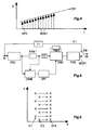
- Fig. 4 Each original first field OFFI is followed by a motion compensated second field MCSFI depicted by a dashed line.
- the invention can be used for 100Hz upconversion of a film source, suitable for display on a TV receiver with 100Hz scanning. In this case each original first field OFFI is followed by three interpolated fields MCSFI (dashed and dotted lines).
- the inventive method is suited for reducing conversion artefacts when film source images are converted into interlace format of at least doubled picture frequency, wherein motion compensated fields of one type of said interlace format - e.g. second fields - are generated between non-motion compensated fields of the other type - e.g. first fields - of said interlace format.
- the inventive apparatus is suited for reducing conversion artefacts when film source images are converted into interlace format of at least doubled picture frequency and includes:
- FIG. 5 One implementation of an inventive apparatus is shown in Fig. 5.
- this would be placed on the output of a telecine or other film projection device.
- this would be enabled when film was being transmitted, either by a signalling means external to the video signal, or by a film mode detector, for example that described in EP-A-0567072.
- a film mode detector for example that described in EP-A-0567072.
- it is checked for every vertically adjacent pixel pair, if the amplitudes of the vertically intermediate pixels of the both adjacent fields lay between the amplitudes of the pixel pair.
- the film mode is switched off if this specific number is exceeded.
- the first field, or half image, OFFI of the input signal IN contains the information in the correct temporal position. This field undergoes no further processing and is output directly after a suitable compensating delay ⁇ 1.
- the motion compensated second field MCSFI is generated by the subsequent processing.
- the first processing step is to combine the two received fields in interlace-to-progressive converter means IPCS to recreate the original film image.
- the function of IPCS is depicted in Fig. 6. Time T is again represented by the horizontal axis. The vertical axis represents the vertical position V.
- the progressive scan image output frame OFR is recreated by delaying the first field FI1 with respect to the second field FI2 by one field period FIP.
- the next step in the process is to calculate the motion of each point in the image within motion estimation means DSME. This may be done by a number of different means, using different types of motion estimation and a frame memory FRM1. As long as the result of the process is a motion vector associated with each point in the image, centred on the temporal position of the desired output field MCSFI, the precise means to provide these vectors is unimportant, aside from the fact that different methods will provide different levels of performance for different costs.
- this motion estimation is done using double sided motion estimation based on the luminance signal, described fully in WO-A-95/07591 of the applicant.
- this is a full search block matching process with the search window centered on the current block position CBP of the interpolated output field IFI, as shown in Fig. 7.
- the backward half of the motion vector BHMV has a landing point within the backward search window BSW of a backward field BFI.
- the forward half of the motion vector FHMV has a landing point within the forward search window FSW of a forward field FFI.
- Each successive pixel block CBP of a current field or frame IFI is matched with respective candidate pixel blocks within search window BSW - which has a preselected window width - of the backward field or frame having a half of said preselected width and with the corresponding pixel blocks within the corresponding search window FSW of the forward field or frame having a half of said preselected width in order to select a motion vector, the first part of which is related to the location of the best matching block of the backward field or frame and the second part of which is related to the location of the best matching block of the forward field or frame, whereby the current position of said search windows BSW and FSW is related to the position of the current pixel block of said current field or frame.
- the result of this block matching yields a number of candidate vectors for each block which are then post-processed in subsequent vector post-processing means VPP.
- the motion vectors are corrected, i.e. are made reasonable, and smoothed.
- This can be performed as described in EP-A-0 648 052 of the applicant to provide a final output vector for each pixel, representing the best estimate of the motion of that pixel.
- a motion vector related to each block is calculated and for any pixel of the current block, a pixel motion vector is calculated using four motion vectors, that is the motion vector of the current block and the motion vectors of the three adjacent blocks.
- the post-processing means VPP may also attempt to correct for the effects of repeated structures as described in EP-A-0 647 919 and localise the block based motion vectors to provide one motion vector per pixel.
- Such correction of motion vectors includes the following steps:
- a measure of confidence of the motion vector can be generated in VPP on a pixel by pixel basis as described in EP-A-0 648 047 of the applicant.
- the confidence is low, there is a high probability that the motion vector is incorrect (for example, on material newly uncovered by the passage of a moving object for which no motion information can be correctly found).
- a default motion vector of 0 in both the horizontal and vertical directions is taken.
- signal paths with different interpolation processing - in particular motion compensated interpolation and fallback interpolation - are formed, whereby the output signals of said different signal paths are combined in relation to a measure of confidence which is derived from a minimum motion estimation error of the input video signal, which is in particular block based.
- DSME may use a non-uniform measurement of candidate motion vectors as described in EP-A-0 639 926 of the applicant to calculate the motion vectors.
- the accuracy of this measurement is made non-uniform within the search window by dividing the window into, at least, an area of high precision and an area of lower precision, whereby the density of the used pixel values of the input signal for the motion vector calculation is less than in the area of less precision.
- the output vectors of VPP are applied to double sided motion compensated interpolation means DMCI, shown in more detail in Fig. 8, which may use a further frame memory FRM2 and which generate from the appropriately delayed (further delay means ⁇ 2) progressive picture signal a motion compensated output image IFI2 (progressive frame or field) in the temporal position of the second field FI2 of the television image.
- Each output pixel IP at the position of zero vector ZV is the average of one pixel in the current film frame CFR and one pixel in the previous film frame PFR.
- the two pixels used in the average are selected by applying the measured motion vector (one half HMMVP in frame PFR and one half HMMVC in frame CFR) for the desired output pixel.
- this vector represents accurately the direction of motion DM
- these two pixels will correspond to the same part of the same object in each frame.
- a complete progressively scanned image can be generated in the position of field FI2.
- output DMCI interpolates three intermediate motion compensated output images IFI2 (progressive frames or fields), whereby respective percentages of the components of the motion vectors can be applied to the interpolation of a specific of the three images.
- the final step which may be combined in the interpolator DMCI by directly interpolating a field or three fields only, respectively, is to produce the output field, or fields, MCSFI from the interpolated information. This is done by taking every second line from the progressive image.
- Switch means SW select either field FI1 or the newly generated field, or fields, MCSFI at the output OU of the inventive apparatus depending on the field being transmitted.
- Colour information can be handled in exactly the same way as luminance for the interpolation process, using the motion vectors derived for the luminance signal.
- the invention can also be used in a video signal decoder (TV, VCR, PC, CD-I, CD Video) if the transmitted or recorded signals have been coded using data reduction, e.g. MPEG1 or MPEG2.
- the transmitted/recorded motion information can be used in, or instead of, circuits DSME and/or VPP.
- field OFFI can be the second field FI2.
Landscapes
- Engineering & Computer Science (AREA)
- Multimedia (AREA)
- Signal Processing (AREA)
- Computer Graphics (AREA)
- Television Systems (AREA)
Claims (8)
- Verfahren zur Verminderung von Umwandlungs-Artefakten (DT00), wenn Bilder von einer Filmquelle in das Zeilensprungformat mit wenigstens der doppelten Bildfrequenz umgewandelt werden, dadurch gekennzeichnet, daß bewegungskompensierte Halbbilder (MCSFI) von einem Typ des Zeilensprungformats - z.B. zweite Halbbilder (FI2) - zwischen nicht bewegungskompensierten Halbbildern (OFFI) des anderen Typs - z.B. erste Halbbilder (FI1) - des Zeilensprungformats erzeugt werden (DMCI, PIDS, SW).
- Verfahren nach Anspruch 1, bei dem drei bewegungskompensierte Halbbilder (MCSFI) zwischen jedem Paar der nicht bewegungskompensierten Halbbilder (OFFI) erzeugt werden.
- Verfahren nach Anspruch 1 oder 2, bei dem die Erzeugung der bewegungskompensierten Halbbilder (MCSFI) in einem Fernsehempfänger oder einem Videorecorder oder einem Videodekoder zur Korrektur nach der Übertragung oder in einem Studio zur Korrektur vor der Übertragung oder Aufzeichnung stattfindet.
- Verfahren nach einem der Ansprüche 1 bis 3, bei dem zur Bestimmung (DSME) der Bewegungsinformation für die Bewegungskompensation eine volle Such-Block-Anpassung ausgeführt wird, wobei das Suchfenster auf die gegenwärtige Blockposition (CBP) des interpolierten Ausgangs-Halbbildes (IFI) zentriert ist, und wobei die hintere Hälfte des Bewegungs-Vektors (BHMV) einen Landepunkt innerhalb des hinteren Suchfensters (BSW) eines hinteren Halbbildes hat und die vordere Hälfte des Bewegungs-Vektors (FHMV) einen Landepunkt innerhalb des vorderen Suchfensters (FSW) eines vorderen Halbbildes (FFI) hat.
- Verfahren nach einem der Ansprüche 1 bis 4, bei dem die Erzeugung der bewegungskompensierten Halbbilder (MCSFI) ausgeführt wird (DMCI, FRM2, PIDS), indem eine doppelseitige bewegungskompensierte Interpolation verwendet wird.
- Verfahren nach einem der Ansprüche 1 bis 5, bei dem die Bilder von einer Filmquelle digital unter Verwendung von Datenverminderung kodiert und entsprechend vor der Umwandlung dekodiert worden sind, insbesondere durch Verwendung einer MPEG1- oder MPEG2-Kodierung und durch Verwendung der auf diese Kodierung bezogenen Bewegungsinformationen für die Bewegungskompensation.
- Vorrichtung zur Verminderung von Umwandlungs-Artefakten (DT00), wenn Bilder von einer Filmquelle in Zeilensprungformat mit wenigstens der doppelten Bildfrequenz unter verwendung des Verfahrens nach einem der Ansprüche 1 bis 6 umgewandelt werden, gekennzeichnet durch:Wandlermittel (IPCS) zur Umwandlung von Zeilensprung- in progressive Signale, die jedes Paar von Zeilensprung-Halbbildern wiederherstellen, um ein progressives Signal zu bilden, das einem Vollbild des ursprünglichen Filmquellen-Bildes (OFR) entspricht;Bewegungs-Abschätzungsmittel (DSME, FRM1), die für jedes Pixel in den wiederhergestellten Bildern (OFR) Bewegungs-Vektoren berechnen;nachfolgende Vektor-Nachverarbeitungsmittel (VPP), die die in den Bewegungs-Abschätzungsmitteln berechneten Bewegungs-Vektoren korrigieren;doppelseitige bewegungskompensierte Interpolationsmittel (DMCI), die auf die geeignet verzögerten (τ2) wiederhergestellten Bilder (OFR) unter Verwendung der korrigierten Bewegungs-Vektoren einwirken;Schaltmittel (SW), die das Ausgangssignal entweder von einem geeignet verzögerten (τ1) Eingangs-Halbbild (IN) oder von einem verarbeiteten Bild von den Interpolationsmitteln (DMCI, PIDS) erzeugen.
- Vorrichtung nach Anspruch 7, bei der in den Bewegungs-Abschätzungsmitteln (DSME, FRM1) eine volle Suchblock-Anpassung ausgeführt wird, wobei das Suchfenster auf die gegenwärtige Blockposition (CBP) des interpolierten Ausgangs-Halbbildes (IPI) zentriert wird, und wobei die hintere Hälfte des Bewegungs-Vektors (BHMV) einen Landepunkt innerhalb des hinteren Suchfensters (BSW) eines hinteren Halbbildes (BFI) hat und die vordere Hälfte des Bewegungs-Vektors (FHMV) einen Landepunkt innerhalb des vorderen Suchfensters (FSW) eines vorderen Halbbildes hat.
Priority Applications (1)
| Application Number | Priority Date | Filing Date | Title |
|---|---|---|---|
| EP19950104170 EP0675643B1 (de) | 1994-03-30 | 1995-03-22 | Verfahren und Gerät zur Reduzierung von Umwandlungsartefakten |
Applications Claiming Priority (3)
| Application Number | Priority Date | Filing Date | Title |
|---|---|---|---|
| EP94400729 | 1994-03-30 | ||
| EP94400729 | 1994-03-30 | ||
| EP19950104170 EP0675643B1 (de) | 1994-03-30 | 1995-03-22 | Verfahren und Gerät zur Reduzierung von Umwandlungsartefakten |
Publications (2)
| Publication Number | Publication Date |
|---|---|
| EP0675643A1 EP0675643A1 (de) | 1995-10-04 |
| EP0675643B1 true EP0675643B1 (de) | 1999-07-21 |
Family
ID=26137483
Family Applications (1)
| Application Number | Title | Priority Date | Filing Date |
|---|---|---|---|
| EP19950104170 Expired - Lifetime EP0675643B1 (de) | 1994-03-30 | 1995-03-22 | Verfahren und Gerät zur Reduzierung von Umwandlungsartefakten |
Country Status (1)
| Country | Link |
|---|---|
| EP (1) | EP0675643B1 (de) |
Families Citing this family (5)
| Publication number | Priority date | Publication date | Assignee | Title |
|---|---|---|---|---|
| EP0883298A3 (de) * | 1997-06-04 | 2000-03-29 | Hitachi, Ltd. | Vorrichtung zur Umsetzung von Bildsignalen sowie Fernsehempfänger |
| FR2773038B1 (fr) * | 1997-12-24 | 2000-02-25 | Thomson Multimedia Sa | Procede et dispositif d'interpolation d'images a partir de donnees video codees mpeg |
| JP3596521B2 (ja) | 2001-12-13 | 2004-12-02 | ソニー株式会社 | 画像信号処理装置及び方法 |
| CN100401763C (zh) * | 2003-05-16 | 2008-07-09 | 索尼株式会社 | 运动补偿设备和方法 |
| EP1592247A1 (de) * | 2004-04-30 | 2005-11-02 | Matsushita Electric Industrial Co., Ltd. | Blocktyp adaptive Bewegungskompensation |
Family Cites Families (3)
| Publication number | Priority date | Publication date | Assignee | Title |
|---|---|---|---|---|
| EP0294962B1 (de) * | 1987-06-09 | 1995-07-19 | Sony Corporation | Bewertung von Bewegungsvektoren in Fernsehbildern |
| EP0431116B1 (de) * | 1989-05-29 | 1994-05-04 | Philips Patentverwaltung GmbH | Schaltungsanordnung zum verringern des zeilen- und kantenflimmerns bei fernsehbildern und interpolationsschaltung |
| DE4213551A1 (de) * | 1992-04-24 | 1993-10-28 | Thomson Brandt Gmbh | Verfahren und Vorrichtung zur Film-Mode-Detektion |
-
1995
- 1995-03-22 EP EP19950104170 patent/EP0675643B1/de not_active Expired - Lifetime
Also Published As
| Publication number | Publication date |
|---|---|
| EP0675643A1 (de) | 1995-10-04 |
Similar Documents
| Publication | Publication Date | Title |
|---|---|---|
| US5610662A (en) | Method and apparatus for reducing conversion artifacts | |
| US5221966A (en) | Video signal production from cinefilm originated material | |
| US6118488A (en) | Method and apparatus for adaptive edge-based scan line interpolation using 1-D pixel array motion detection | |
| US5642170A (en) | Method and apparatus for motion compensated interpolation of intermediate fields or frames | |
| KR950006774B1 (ko) | 움직임보상예측방법 | |
| US20040046891A1 (en) | Frame interpolation and apparatus using frame interpolation | |
| US7254264B2 (en) | Method and device for generating 3D images | |
| JP4083265B2 (ja) | 画像信号の方式変換方法および装置 | |
| US8175163B2 (en) | System and method for motion compensation using a set of candidate motion vectors obtained from digital video | |
| JPH08275116A (ja) | インタレースされたビデオフレームシーケンスを順次走査シーケンスに変換する手段および装置 | |
| JP3222496B2 (ja) | ビデオ信号処理装置 | |
| US20090208123A1 (en) | Enhanced video processing using motion vector data | |
| KR20040054758A (ko) | 비디오 이미지들의 향상된 공간 해상도 | |
| JP2003163894A (ja) | 適応動き補償型フレーム及び/又はフィールドレート変換装置及びその方法 | |
| JPH0644815B2 (ja) | 動物体の動き内挿装置 | |
| US7218354B2 (en) | Image processing device and method, video display device, and recorded information reproduction device | |
| CN101416523A (zh) | 具有抗补偿伪影保护的运动补偿帧速率转换 | |
| GB2240232A (en) | Converting field rate of telecine signal | |
| JP2001024988A (ja) | 画像信号の動き補償フレーム数変換方式および装置 | |
| JPH11112940A (ja) | 動きベクトルの生成方法および装置 | |
| KR20050080862A (ko) | 중첩된 블록 기반 움직임 추정에 의한 움직임 보상 보간방법 및 그를 적용한 프레임 레이트 변환 장치 | |
| US5355169A (en) | Method for processing a digital video signal having portions acquired with different acquisition characteristics | |
| EP0675643B1 (de) | Verfahren und Gerät zur Reduzierung von Umwandlungsartefakten | |
| JP2004519901A (ja) | 動き推定の容易化 | |
| US5430489A (en) | Video to film conversion |
Legal Events
| Date | Code | Title | Description |
|---|---|---|---|
| PUAI | Public reference made under article 153(3) epc to a published international application that has entered the european phase |
Free format text: ORIGINAL CODE: 0009012 |
|
| AK | Designated contracting states |
Kind code of ref document: A1 Designated state(s): DE FR GB IT |
|
| 17P | Request for examination filed |
Effective date: 19960308 |
|
| RAP1 | Party data changed (applicant data changed or rights of an application transferred) |
Owner name: THOMSON MULTIMEDIA |
|
| 17Q | First examination report despatched |
Effective date: 19980421 |
|
| GRAG | Despatch of communication of intention to grant |
Free format text: ORIGINAL CODE: EPIDOS AGRA |
|
| GRAG | Despatch of communication of intention to grant |
Free format text: ORIGINAL CODE: EPIDOS AGRA |
|
| GRAG | Despatch of communication of intention to grant |
Free format text: ORIGINAL CODE: EPIDOS AGRA |
|
| GRAH | Despatch of communication of intention to grant a patent |
Free format text: ORIGINAL CODE: EPIDOS IGRA |
|
| GRAH | Despatch of communication of intention to grant a patent |
Free format text: ORIGINAL CODE: EPIDOS IGRA |
|
| GRAA | (expected) grant |
Free format text: ORIGINAL CODE: 0009210 |
|
| AK | Designated contracting states |
Kind code of ref document: B1 Designated state(s): DE FR GB IT |
|
| REF | Corresponds to: |
Ref document number: 69510851 Country of ref document: DE Date of ref document: 19990826 |
|
| ET | Fr: translation filed | ||
| ITF | It: translation for a ep patent filed | ||
| PLBE | No opposition filed within time limit |
Free format text: ORIGINAL CODE: 0009261 |
|
| STAA | Information on the status of an ep patent application or granted ep patent |
Free format text: STATUS: NO OPPOSITION FILED WITHIN TIME LIMIT |
|
| 26N | No opposition filed | ||
| REG | Reference to a national code |
Ref country code: GB Ref legal event code: 746 Effective date: 20010813 |
|
| REG | Reference to a national code |
Ref country code: GB Ref legal event code: IF02 |
|
| REG | Reference to a national code |
Ref country code: FR Ref legal event code: D6 |
|
| PGFP | Annual fee paid to national office [announced via postgrant information from national office to epo] |
Ref country code: FR Payment date: 20110405 Year of fee payment: 17 Ref country code: IT Payment date: 20110316 Year of fee payment: 17 |
|
| PGFP | Annual fee paid to national office [announced via postgrant information from national office to epo] |
Ref country code: DE Payment date: 20110322 Year of fee payment: 17 Ref country code: GB Payment date: 20110329 Year of fee payment: 17 |
|
| GBPC | Gb: european patent ceased through non-payment of renewal fee |
Effective date: 20120322 |
|
| REG | Reference to a national code |
Ref country code: FR Ref legal event code: ST Effective date: 20121130 |
|
| REG | Reference to a national code |
Ref country code: DE Ref legal event code: R119 Ref document number: 69510851 Country of ref document: DE Effective date: 20121002 |
|
| PG25 | Lapsed in a contracting state [announced via postgrant information from national office to epo] |
Ref country code: GB Free format text: LAPSE BECAUSE OF NON-PAYMENT OF DUE FEES Effective date: 20120322 Ref country code: FR Free format text: LAPSE BECAUSE OF NON-PAYMENT OF DUE FEES Effective date: 20120402 |
|
| PG25 | Lapsed in a contracting state [announced via postgrant information from national office to epo] |
Ref country code: IT Free format text: LAPSE BECAUSE OF NON-PAYMENT OF DUE FEES Effective date: 20120322 |
|
| PG25 | Lapsed in a contracting state [announced via postgrant information from national office to epo] |
Ref country code: DE Free format text: LAPSE BECAUSE OF NON-PAYMENT OF DUE FEES Effective date: 20121002 |