EP0675752B1 - Systeme et methode pour la combinaison de recipients separes contenant un fluide biologique - Google Patents
Systeme et methode pour la combinaison de recipients separes contenant un fluide biologique Download PDFInfo
- Publication number
- EP0675752B1 EP0675752B1 EP93900579A EP93900579A EP0675752B1 EP 0675752 B1 EP0675752 B1 EP 0675752B1 EP 93900579 A EP93900579 A EP 93900579A EP 93900579 A EP93900579 A EP 93900579A EP 0675752 B1 EP0675752 B1 EP 0675752B1
- Authority
- EP
- European Patent Office
- Prior art keywords
- gas
- biological fluid
- assembly
- receiving container
- gas inlet
- Prior art date
- Legal status (The legal status is an assumption and is not a legal conclusion. Google has not performed a legal analysis and makes no representation as to the accuracy of the status listed.)
- Expired - Lifetime
Links
- 239000013060 biological fluid Substances 0.000 title claims abstract description 76
- 238000000034 method Methods 0.000 title claims abstract description 27
- 238000012545 processing Methods 0.000 title claims description 31
- 210000000265 leukocyte Anatomy 0.000 claims abstract description 46
- 238000011176 pooling Methods 0.000 claims abstract description 43
- 239000012530 fluid Substances 0.000 claims description 26
- 238000004891 communication Methods 0.000 claims description 12
- 238000011144 upstream manufacturing Methods 0.000 claims description 7
- 239000007789 gas Substances 0.000 description 150
- 239000003634 thrombocyte concentrate Substances 0.000 description 69
- 238000012546 transfer Methods 0.000 description 30
- 238000011084 recovery Methods 0.000 description 15
- 210000004369 blood Anatomy 0.000 description 13
- 239000008280 blood Substances 0.000 description 13
- 239000003570 air Substances 0.000 description 10
- 239000000306 component Substances 0.000 description 9
- 239000012528 membrane Substances 0.000 description 8
- 230000000712 assembly Effects 0.000 description 7
- 238000000429 assembly Methods 0.000 description 7
- 239000000463 material Substances 0.000 description 7
- 210000002381 plasma Anatomy 0.000 description 7
- 230000000717 retained effect Effects 0.000 description 6
- 239000012503 blood component Substances 0.000 description 5
- 239000000835 fiber Substances 0.000 description 5
- BJQHLKABXJIVAM-UHFFFAOYSA-N bis(2-ethylhexyl) phthalate Chemical compound CCCCC(CC)COC(=O)C1=CC=CC=C1C(=O)OCC(CC)CCCC BJQHLKABXJIVAM-UHFFFAOYSA-N 0.000 description 4
- -1 for example Substances 0.000 description 3
- 239000004800 polyvinyl chloride Substances 0.000 description 3
- 239000000243 solution Substances 0.000 description 3
- BJQHLKABXJIVAM-BGYRXZFFSA-N 1-o-[(2r)-2-ethylhexyl] 2-o-[(2s)-2-ethylhexyl] benzene-1,2-dicarboxylate Chemical compound CCCC[C@H](CC)COC(=O)C1=CC=CC=C1C(=O)OC[C@H](CC)CCCC BJQHLKABXJIVAM-BGYRXZFFSA-N 0.000 description 2
- 241000894006 Bacteria Species 0.000 description 2
- MQIUGAXCHLFZKX-UHFFFAOYSA-N Di-n-octyl phthalate Natural products CCCCCCCCOC(=O)C1=CC=CC=C1C(=O)OCCCCCCCC MQIUGAXCHLFZKX-UHFFFAOYSA-N 0.000 description 2
- 229920012485 Plasticized Polyvinyl chloride Polymers 0.000 description 2
- 230000002411 adverse Effects 0.000 description 2
- 239000010836 blood and blood product Substances 0.000 description 2
- 229940125691 blood product Drugs 0.000 description 2
- 210000004027 cell Anatomy 0.000 description 2
- 235000015097 nutrients Nutrition 0.000 description 2
- 210000004623 platelet-rich plasma Anatomy 0.000 description 2
- 229920000515 polycarbonate Polymers 0.000 description 2
- 239000004417 polycarbonate Substances 0.000 description 2
- 229920000915 polyvinyl chloride Polymers 0.000 description 2
- 239000011148 porous material Substances 0.000 description 2
- 238000003860 storage Methods 0.000 description 2
- 239000000725 suspension Substances 0.000 description 2
- JNXDCMUUZNIWPQ-UHFFFAOYSA-N trioctyl benzene-1,2,4-tricarboxylate Chemical compound CCCCCCCCOC(=O)C1=CC=C(C(=O)OCCCCCCCC)C(C(=O)OCCCCCCCC)=C1 JNXDCMUUZNIWPQ-UHFFFAOYSA-N 0.000 description 2
- 238000009736 wetting Methods 0.000 description 2
- FAPWRFPIFSIZLT-UHFFFAOYSA-M Sodium chloride Chemical compound [Na+].[Cl-] FAPWRFPIFSIZLT-UHFFFAOYSA-M 0.000 description 1
- 239000004676 acrylonitrile butadiene styrene Substances 0.000 description 1
- 230000001464 adherent effect Effects 0.000 description 1
- 239000012080 ambient air Substances 0.000 description 1
- 239000003146 anticoagulant agent Substances 0.000 description 1
- 229940127219 anticoagulant drug Drugs 0.000 description 1
- 210000001185 bone marrow Anatomy 0.000 description 1
- UBAZGMLMVVQSCD-UHFFFAOYSA-N carbon dioxide;molecular oxygen Chemical compound O=O.O=C=O UBAZGMLMVVQSCD-UHFFFAOYSA-N 0.000 description 1
- 230000005465 channeling Effects 0.000 description 1
- 230000001010 compromised effect Effects 0.000 description 1
- 230000000779 depleting effect Effects 0.000 description 1
- 238000011161 development Methods 0.000 description 1
- 239000000385 dialysis solution Substances 0.000 description 1
- 230000000694 effects Effects 0.000 description 1
- 238000001914 filtration Methods 0.000 description 1
- 239000012510 hollow fiber Substances 0.000 description 1
- 230000036512 infertility Effects 0.000 description 1
- 230000000977 initiatory effect Effects 0.000 description 1
- 238000004519 manufacturing process Methods 0.000 description 1
- 244000005700 microbiome Species 0.000 description 1
- 230000035699 permeability Effects 0.000 description 1
- 230000001766 physiological effect Effects 0.000 description 1
- 238000009832 plasma treatment Methods 0.000 description 1
- 229920003023 plastic Polymers 0.000 description 1
- 239000004033 plastic Substances 0.000 description 1
- 229920000728 polyester Polymers 0.000 description 1
- 229920000098 polyolefin Polymers 0.000 description 1
- 229920002635 polyurethane Polymers 0.000 description 1
- 239000004814 polyurethane Substances 0.000 description 1
- 238000002360 preparation method Methods 0.000 description 1
- 238000007789 sealing Methods 0.000 description 1
- 238000004062 sedimentation Methods 0.000 description 1
- 238000000926 separation method Methods 0.000 description 1
- 239000011780 sodium chloride Substances 0.000 description 1
- 229910001220 stainless steel Inorganic materials 0.000 description 1
- 239000010935 stainless steel Substances 0.000 description 1
- 239000012209 synthetic fiber Substances 0.000 description 1
- 229920002994 synthetic fiber Polymers 0.000 description 1
- 230000001225 therapeutic effect Effects 0.000 description 1
- 238000013022 venting Methods 0.000 description 1
- 230000035899 viability Effects 0.000 description 1
Images
Classifications
-
- A—HUMAN NECESSITIES
- A61—MEDICAL OR VETERINARY SCIENCE; HYGIENE
- A61M—DEVICES FOR INTRODUCING MEDIA INTO, OR ONTO, THE BODY; DEVICES FOR TRANSDUCING BODY MEDIA OR FOR TAKING MEDIA FROM THE BODY; DEVICES FOR PRODUCING OR ENDING SLEEP OR STUPOR
- A61M1/00—Suction or pumping devices for medical purposes; Devices for carrying-off, for treatment of, or for carrying-over, body-liquids; Drainage systems
- A61M1/02—Blood transfusion apparatus
- A61M1/0209—Multiple bag systems for separating or storing blood components
-
- A—HUMAN NECESSITIES
- A61—MEDICAL OR VETERINARY SCIENCE; HYGIENE
- A61M—DEVICES FOR INTRODUCING MEDIA INTO, OR ONTO, THE BODY; DEVICES FOR TRANSDUCING BODY MEDIA OR FOR TAKING MEDIA FROM THE BODY; DEVICES FOR PRODUCING OR ENDING SLEEP OR STUPOR
- A61M1/00—Suction or pumping devices for medical purposes; Devices for carrying-off, for treatment of, or for carrying-over, body-liquids; Drainage systems
- A61M1/02—Blood transfusion apparatus
- A61M1/0209—Multiple bag systems for separating or storing blood components
- A61M1/0218—Multiple bag systems for separating or storing blood components with filters
-
- A—HUMAN NECESSITIES
- A61—MEDICAL OR VETERINARY SCIENCE; HYGIENE
- A61M—DEVICES FOR INTRODUCING MEDIA INTO, OR ONTO, THE BODY; DEVICES FOR TRANSDUCING BODY MEDIA OR FOR TAKING MEDIA FROM THE BODY; DEVICES FOR PRODUCING OR ENDING SLEEP OR STUPOR
- A61M1/00—Suction or pumping devices for medical purposes; Devices for carrying-off, for treatment of, or for carrying-over, body-liquids; Drainage systems
- A61M1/02—Blood transfusion apparatus
- A61M1/0209—Multiple bag systems for separating or storing blood components
- A61M1/0231—Multiple bag systems for separating or storing blood components with gas separating means, e.g. air outlet through microporous membrane or gas bag
-
- A—HUMAN NECESSITIES
- A61—MEDICAL OR VETERINARY SCIENCE; HYGIENE
- A61M—DEVICES FOR INTRODUCING MEDIA INTO, OR ONTO, THE BODY; DEVICES FOR TRANSDUCING BODY MEDIA OR FOR TAKING MEDIA FROM THE BODY; DEVICES FOR PRODUCING OR ENDING SLEEP OR STUPOR
- A61M1/00—Suction or pumping devices for medical purposes; Devices for carrying-off, for treatment of, or for carrying-over, body-liquids; Drainage systems
- A61M1/36—Other treatment of blood in a by-pass of the natural circulatory system, e.g. temperature adaptation, irradiation ; Extra-corporeal blood circuits
- A61M1/3621—Extra-corporeal blood circuits
- A61M1/3643—Priming, rinsing before or after use
- A61M1/3644—Mode of operation
- A61M1/3646—Expelling the residual body fluid after use, e.g. back to the body
-
- A—HUMAN NECESSITIES
- A61—MEDICAL OR VETERINARY SCIENCE; HYGIENE
- A61M—DEVICES FOR INTRODUCING MEDIA INTO, OR ONTO, THE BODY; DEVICES FOR TRANSDUCING BODY MEDIA OR FOR TAKING MEDIA FROM THE BODY; DEVICES FOR PRODUCING OR ENDING SLEEP OR STUPOR
- A61M1/00—Suction or pumping devices for medical purposes; Devices for carrying-off, for treatment of, or for carrying-over, body-liquids; Drainage systems
- A61M1/36—Other treatment of blood in a by-pass of the natural circulatory system, e.g. temperature adaptation, irradiation ; Extra-corporeal blood circuits
- A61M1/3621—Extra-corporeal blood circuits
- A61M1/3643—Priming, rinsing before or after use
- A61M1/3644—Mode of operation
- A61M1/3652—Mode of operation using gas, e.g. air
-
- A—HUMAN NECESSITIES
- A61—MEDICAL OR VETERINARY SCIENCE; HYGIENE
- A61M—DEVICES FOR INTRODUCING MEDIA INTO, OR ONTO, THE BODY; DEVICES FOR TRANSDUCING BODY MEDIA OR FOR TAKING MEDIA FROM THE BODY; DEVICES FOR PRODUCING OR ENDING SLEEP OR STUPOR
- A61M2202/00—Special media to be introduced, removed or treated
- A61M2202/04—Liquids
- A61M2202/0413—Blood
- A61M2202/0439—White blood cells; Leucocytes
-
- A—HUMAN NECESSITIES
- A61—MEDICAL OR VETERINARY SCIENCE; HYGIENE
- A61M—DEVICES FOR INTRODUCING MEDIA INTO, OR ONTO, THE BODY; DEVICES FOR TRANSDUCING BODY MEDIA OR FOR TAKING MEDIA FROM THE BODY; DEVICES FOR PRODUCING OR ENDING SLEEP OR STUPOR
- A61M2205/00—General characteristics of the apparatus
- A61M2205/75—General characteristics of the apparatus with filters
- A61M2205/7527—General characteristics of the apparatus with filters liquophilic, hydrophilic
-
- A—HUMAN NECESSITIES
- A61—MEDICAL OR VETERINARY SCIENCE; HYGIENE
- A61M—DEVICES FOR INTRODUCING MEDIA INTO, OR ONTO, THE BODY; DEVICES FOR TRANSDUCING BODY MEDIA OR FOR TAKING MEDIA FROM THE BODY; DEVICES FOR PRODUCING OR ENDING SLEEP OR STUPOR
- A61M2205/00—General characteristics of the apparatus
- A61M2205/75—General characteristics of the apparatus with filters
- A61M2205/7536—General characteristics of the apparatus with filters allowing gas passage, but preventing liquid passage, e.g. liquophobic, hydrophobic, water-repellent membranes
Definitions
- This invention relates to a system and a method for processing separate containers of biological fluid.
- PC platelet concentrate
- platelets are notorious for being "sticky", an expression reflecting the tendency of platelets suspended in blood plasma to adhere to any non-physiological surface (e.g., the surfaces of the components of a system for processing biological fluid) to which they are exposed. Under many circumstances, they also adhere strongly to each other.
- a biological fluid such as a platelet containing suspension
- a biological fluid such as a platelet containing suspension
- it will pool large amounts (e.g. multiple units) of the fluid.
- it will also leukocyte deplete the fluid and maximize the recovery of platelets.
- US-A-4334535 shows a pooling system for use with nutrients and dialysis solutions.
- EP-A-0455215 shows a blood-collection device with a tube branching from the blood-collecting tube which is connected to a filter.
- the filter allows passage of gas but substantially prevents passage of blood, bacteria, microorganism and the like.
- the fibers or membrane are preferably treated in order to reduce or eliminate platelet adherence to the medium. Any treatment which reduces or eliminates platelet adhesion is included within the scope of the present invention.
- the fibers may be surface modified as disclosed in U.S. Patent 4,880,548, in order to increase the critical wetting surface tension (CWST) of the fibers and to be less adherent of platelets.
- CWST critical wetting surface tension
- a preferred range of CWST for a porous medium according to the invention is above about 70 mNm -1 (70 dynes/cm) more preferably above about 90 mNm -1 (90 dynes/cm).
- the porous medium may be pre-formed, single or multi-layered, and/or may be treated to modify the fiber surfaces either before or after forming the fibrous lay-up.
- the porous medium may be configured in any suitable fashion, such as a flat sheet, a corrugated sheet, a web, hollow fibers, or a membrane.
- a system for processing a plurality of units of biological fluid in a plurality of biological fluid source containers comprising a receiving container; a pooling assembly upstream of the receiving container, capable of being interposed between the source containers and the receiving container and providing fluid communication therewith; and a gas inlet including a liquophobic porous medium for passing gas therethrough in fluid communication with the pooling assembly.
- a method for processing biological fluid comprising introducing gas through at least one gas inlet including a porous medium for passing gas therethrough, and into a plurality of source containers of biological fluid; and passing the biological fluid from the plurality of source containers through a pooling assembly to a receiving container.
- the processes and systems of the present invention provide for increased yield of a biological fluid, since valuable fluid that would normally be retained in various elements of a biological fluid processing system may now be recovered.
- the present invention also provides for reduced processing time and operator labor.
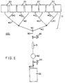
- the Figure is an embodiment of a biological fluid processing system comprising a manifold assembly according to the invention.
- units of biological fluid particularly PC, which are in separate source containers, are passed through a biological fluid processing system which maximizes recovery of the biological fluid into a single receiving container.
- the processing system may also include a leukocyte depletion assembly that is interposed between the source containers and the receiving container.
- Manifold assembly 100 may include containers 20, each suitable for holding at least one unit of a biological fluid such as PC, in fluid communication with a pooling assembly 21.
- the pooling assembly 21 includes a network or plurality of conduits 40 that converge into a single conduit 60 at outlet or junction 50. Some of the conduits 40 function as inlets from the source containers 20.
- pooling assembly 21 may include a housing having at least two inlets and an outlet. The outlet or junction 50 of the pooling assembly 21 is in fluid communication with a receiving or transfer container 22.
- fluid communication with the receiving container 22 is preferably established by a conduit 60.
- a conduit 60 Interposed in the conduit 60 between the outlet or junction 50 and the container 22 may be at least one device or assembly.
- the manifold assembly 100 may include a gas inlet 30, a drip chamber 31, a leukocyte depletion assembly 32, and a gas outlet 33.
- the source and receiving containers which are used in the biological fluid processing assembly may be constructed of any material compatible with biological fluids.
- these containers are already known in the art.
- blood collection and satellite bags are typically made from plasticized PVC, e.g. PVC plasticized with dioctylphthalate, diethylhexylphthalate, or trioctyltrimellitate.
- the bags may also be formed from a polyolefin, polyurethane, polyester, or a polycarbonate.
- the pooling assembly of the instant invention provides fluid communication between at least two source containers and a receiving container, more preferably between three or more source containers and a receiving container, preferably by channeling multiple flow paths into a single flow path.
- the pooling assembly 21 preferably comprises a plurality of conduits 40 and an outlet or junction 50.
- the conduits can be configured in a number of ways, the pooling assembly preferably comprises a network or tiered arrangement of conduits 40, preferably including one or more junctions, such as one or more Y-connectors.
- the conduits provide fluid communication between the source of the biological fluid, such as separate unit containers 20, and a multiple unit container, such as transfer or receiving container 22.
- a clamp, seal, valve, transfer leg closure, or the like, may be located within or on at least one of the conduits.
- the pooling assembly 21 may include at least one device having multiple inlets and a single outlet in fluid communication with junction 50.
- the pooling assembly used in the instant invention may be constructed of any material compatible with a biological fluid.
- the pooling assembly may be composed of a non-flexible material, for example, acrylonitrile butadiene styrene (ABS), polycarbonate, or stainless steel.
- ABS acrylonitrile butadiene styrene
- it may be composed of a flexible material, such as polyvinyl chloride (PVC), or plasticized PVC, e.g., PVC plasticized with dioctylphthalate, diethylhexylphthalate, or trioctyltrimellitate.
- PVC polyvinyl chloride
- plasticized PVC e.g., PVC plasticized with dioctylphthalate, diethylhexylphthalate, or trioctyltrimellitate.
- the biological fluid processing system may include a drip chamber 31.
- drip chamber 31 may be used to prevent gas from reaching a leukocyte depletion assembly 32 and/or the receiving container 22 downstream of the drip chamber, and for maximizing recovery of the biological fluid.
- the drip chambers which may be used in the biological fluid processing assembly may be constructed of any material compatible with biological fluid and gas.
- the drip chamber may include at least one porous element, preferably a liquophobic porous membrane, that allows gas into a biological fluid processing system and/or allows gas to be separated from a biological fluid being processed, e.g., allows gas out of a biological fluid processing system, but resists the passage of biological fluid.
- the porous element would then function as a gas inlet and/or a gas outlet as later discussed.
- the porous element may be positioned in a conduit, or, more preferably, it may be included in a housing of the drip chamber.
- the surface of the element may be oriented in a variety of ways with respect to the flow of the biological fluid. For example, two porous elements may be placed at opposite ends or sides of the drip chamber, or a single element may be offset within the drip chamber.
- the leukocyte depletion assembly 32 comprises at least one porous medium which removes leukocytes from the biological fluid.
- Exemplary leukocyte depletion media for use with a biological fluid such as PC are disclosed in U.S. Patent 4,880,548.
- the leukocyte depletion assembly 32 may be positioned in the manifold assembly in a variety of ways. For example, it may be located downstream of the outlet of the pooling assembly 50 and the drip chamber 31.
- a plurality of leukocyte depletion assemblies may be used in connection with the pooling assembly of the instant invention.
- a plurality of leukocyte depletion assemblies may be placed in a plurality of pooling assembly inlets, i.e., in direct communication with the individual source containers of biological fluid.
- a plurality of leukocyte depletion assemblies may be placed more downstream in the pooling assembly, i.e., at similar or different tiers of the pooling assembly.
- a leukocyte depletion assembly 32 is interposed between the source containers 20 and the receiving container 22, for example, in conduit 60.
- a gas inlet and/or a gas outlet may be used to maximize the recovery of biological fluid in receiving or transfer container 22.
- the gas inlet 30 and the gas outlet 33 may be, respectively, upstream and downstream of the leukocyte depletion assembly 32. More preferably, as exemplified in the Figure, the gas inlet 30 is downstream of the outlet of the pooling assembly 50 and upstream of the drip chamber 31, which is upstream of the leukocyte depletion assembly 32, while the gas outlet 33 is downstream, interposed between the leukocyte depletion assembly 32 and the receiving or transfer container 22.
- a gas inlet and/or a gas outlet may be positioned in a drip chamber, a conduit, or the receiving and/or source containers.
- the gas inlet is a porous element which allows gas into a biological fluid processing system.
- the gas inlet may provide for increasing the recovery of a valuable biological fluid (e.g., PC) that may otherwise be retained in various components of the manifold assembly during processing and would otherwise be lost.
- a valuable biological fluid e.g., PC
- the gas outlet is a porous element which allows gas to be separated from a biological fluid being processed.
- the gas outlet allows gas that may be present in a biological fluid processing system out of the system.
- the gas outlet may provide for minimizing the volume of gases that remain in, or in contact with, a biological fluid during processing.
- the gas outlet may also allow gas into the biological fluid processing system.
- the gas inlet and gas outlet should be chosen so that the sterility of the system is not compromised.
- the gas inlet and gas outlet each comprise at least one porous element designed to allow gas to pass therethrough.
- a variety of materials may be used, provided the requisite properties of the porous element are achieved. These properties include the necessary strength to handle the differential pressures encountered in use and the ability to provide the desired filtration capability while providing the desired permeability without the application of excessive pressure.
- the porous elements of the gas inlet and the gas outlet should also preferably have a pore rating of about 0.2 micrometer or less to preclude bacteria entering the system.
- the gas inlet and gas outlet include at least one liquophobic porous element. Because the liquophobic porous element is not wettable, or poorly wettable, by the biological fluid being processed in the system, gas in the system that contacts the liquophobic element will pass through it, while the biological fluid will not.
- the gas outlet may also include at least one liquophilic porous element, that allows gas to exit, but not enter, the system.
- the gas outlet includes both a liquophobic membrane and a liquophilic membrane.
- the gas inlet and/or the gas outlet may be included in a housing, which may include a cap or closure. Exemplary gas inlets and/or gas outlets and processes for using them are as disclosed in International Publication Nos. WO 91/17809 and WO 92/07656, and U. S. Patent No. 5,126,054.
- the placement of the gas inlet and/or the gas outlet may be optimized to achieve a desired result.
- the gas inlet 30 may be located as far upstream of the manifold outlet or junction 50 as is practical in order to sufficiently maximize the recovery of biological fluid from the manifold assembly 100.
- gas inlets may be located in each of the source containers 20 of the biological fluid to be pooled.
- the gas inlet 30 may be placed in a conduit 40 or downstream of the outlet or junction 50 of the pooling assembly 21.
- the gas outlet 33 may be located in conduit 60 downstream of the outlet or junction 50 and as close to receiving or transfer container 22 as is possible in order to maximize the volume of gas that is removed from the manifold assembly 100.
- the gas outlet may be located in the receiving or transfer container 22 itself.
- the gas inlet or the gas outlet may be located in the drip chamber 31.
- a gas inlet and/or a gas outlet may be interposed between the source containers 20 and the receiving container 22, for example, in conduit 60.
- the pooling assembly may also include a plurality of gas inlets and/or gas outlets in any of the containers, or in any of the conduits communicating with the leukocyte depletion assemblies.
- PC in a plurality of containers 20 passes through the conduits of the pooling assembly 21 and through outlet or junction 50 to receiving or transfer container 22.
- the PC preferably contacts at least one device, assembly, or porous element, e.g., a gas inlet 30, a drip chamber 31, or a gas outlet 33, for preventing gas from reaching a leukocyte depletion assembly or the receiving container, and for maximizing the recovery of the PC, which is interposed between the source containers 20 and the receiving or transfer container 22.
- the PC may also pass through at least one leukocyte depletion assembly 32 which is interposed between the source containers 20 and the receiving or transfer container 22.
- air or gas may be introduced into the source containers 20 through the gas inlet assembly 30 or the gas outlet assembly 33, preferably by using a syringe (not shown).
- air or gas refers to any gaseous fluid, such as sterilized air, oxygen, carbon dioxide, and the like; it is intended that the invention not be limited to the type of gas used.
- the introduced fluid is preferably ambient air or a sterile gas, some non-gaseous fluids may also be suitable.
- fluid that is lighter than the biological fluid and is non-reactive with it is included within the scope of the present invention.
- Introducing gas into the source containers 20 may be accomplished by opening a flow path from the gas inlet 30 or the gas outlet 33 to the appropriate source container 20, while closing the flow path to the receiving or transfer container 22.
- the clamps on the conduits leading to the receiving or transfer container 22 and all but one container 20 may be closed, so that when gas is introduced into the system, gas in the conduit will enter the open container.
- the process includes introducing gas sequentially into the source containers 20. The flow path to each source container may be closed after gas has been introduced into that container.
- the flow path from the gas inlet 30 or the gas outlet 33 is then closed.
- the flow path to the first source container 20 is then opened, and as the PC passes from the first source container 20, and flows through the pooling assembly 21 toward receiving or transfer container 22, it displaces the gas that was ahead of the column of flowing PC; this gas is exhausted or removed from the system.
- the gas may be vented from the system through a porous element in the drip chamber or in the conduit, or preferably, through an open gas outlet 33.
- the gas outlet may be inactivated to prevent gas from entering the system.
- the gas outlet may be inactivated by manually closing the outlet, e.g., by capping or clamping.
- the gas outlet includes a liquophobic element, and more preferably, both a liquophobic element and a liquophilic element, which inactivates the outlet automatically, upon wetting by the PC.
- clamps adjacent to the other source containers are opened, preferably, sequentially, so that PC from the other containers 20 may pass through the pooling assembly 21 toward the receiving or transfer container 22.
- the clamp adjacent to the receiving or transfer container 22 is opened so that the PC can flow into the container 22.
- the clamp adjacent to the receiving or transfer container 22 is opened before the clamps adjacent to the other source containers are opened.
- Initiating the flow of PC from the other source containers also displaces gas ahead of the other units of PC.
- this gas may be collected in drip chamber 31 interposed between the outlet or junction 50 and the receiving or transfer container 22. Passing the PC through a drip chamber 31 may include collecting gas and/or controlling the rate of flow of the PC.
- the drip chamber 31 is typically inverted until the PC fills the drip chamber, at which point the drip chamber is returned to its normal orientation.
- the PC may also be passed through a leukocyte depletion assembly 32 interposed between the outlet or junction 50 of the manifold assembly 21 and the receiving or transfer container 22.
- the leukocyte depletion assembly 32 is located between the gas inlet 30 and the gas outlet 33.
- the gas ahead of the PC may be exhausted through the gas outlet 33 as described previously. Pooled PC is then recovered in the receiving or transfer container 22 and, in accordance with the invention, the introduction of air or gas into the receiving container is eliminated or minimized, so the PC is recovered without collecting air.
- gas may be introduced behind the PC retained in the system.
- the gas that was initially introduced into the source containers 20 through either the gas inlet 30 or the gas outlet 33 will follow the PC as it flows through the conduits. This increases the recovery of the PC, since the gas following the PC "chases" the fluid from the conduits.
- gas may be introduced behind the retained PC by opening gas inlet 30. Additional PC may then be recovered in the receiving or transfer container 22.
- receiving or transfer container 22 may be sealed and separated from the system, without the introduction of air into the container.
- receiving or transfer container 22 is heat sealed, although other methods of sealing are also suitable.
- the gas outlet may be used as a gas inlet, and, conversely, the gas inlet may be used as a gas outlet, at different stages of processing of the PC.
- gas may be introduced and exhausted using a gas inlet and a gas outlet as described above, and the PC is recovered in a receiving or transfer container. Gas may then be introduced through the gas outlet, so that the PC remaining in the containers and/or held up in the leukocyte depletion assembly or assemblies may be collected.
- gas may also be introduced through the gas inlet for a similar effect.
- the manifold assembly 100 may comprise all of the components shown in the Figure, except for the leukocyte depletion assembly 32.
- Another embodiment of the invention may comprise all of the components shown in the Figure except for the gas inlet 30, the leukocyte depletion assembly 32, and the gas outlet 33.
- the drip chamber 31 preferably includes a porous element for venting gas.
- another embodiment of the invention may include only a single porous element interposed between the outlet of the pooling assembly 50 and the receiving or transfer container 22, which allows gas to flow therethrough. In each of these embodiments gas ahead of the flow of the PC and gas pockets moving along the conduit with the flow of PC may be prevented from entering the receiving or transfer container. Further, gas may be introduced behind the flow of PC to maximize recovery of the PC.
- an apparatus for processing biological fluid comprises a conduit having first and second ends and interposed between the first end and the second end, at least one of a gas inlet, a drip chamber, a leukocyte depletion assembly, and a gas outlet.
- an apparatus may comprise a conduit having first and second ends and interposed between the first end and the second end, a gas inlet, a drip chamber, a leukocyte depletion assembly, and a gas outlet.
- At least one of the gas inlet, the drip chamber and the gas outlet may comprise at least one porous element for maximizing recovery of a biological fluid.
- the porous element may comprise at least one liquophobic element, and may also include at least one liquophilic element.
- the invention also encompasses a method for processing biological fluid comprising passing a biological fluid through a conduit having first and second ends and interposed between the first and second ends, at least one of a gas inlet, a drip chamber, a leukocyte depletion assembly, and a gas outlet.
- a method may comprise passing a biological fluid through a conduit having first and second ends and interposed between the first and second ends, a gas inlet, a drip chamber, a leukocyte depletion assembly, and a gas outlet.
- the pooling assembly used to perform this example utilized six units of PC in individual 60 ml single-unit containers, and a 1500 ml storage container, set up in a manner that generally corresponds to that described for the Figure.
- the manifold assembly is arranged generally vertically, with the pooling assembly and the conduit to the receiving container having a total length of about 61mm (24 inches). Clamps on the conduits adjacent to the six single-unit containers of PC were closed, as was the clamp on the conduit between the transfer container and the gas outlet.
- the leukocyte depletion assembly was produced in accordance with U.S. Patent 4,880,548.
- a 60 cm 3 syringe was used to introduce air through the gas inlet and into the source containers.
- the gas outlet was capped.
- the plunger of the syringe was drawn back to the "60 cm 3 " mark, the gas inlet was uncapped, and then the syringe was connected to the gas inlet.
- the clamp to the first single-unit container which contained a unit of PC, was opened, and the plunger of the syringe was pushed forward about 5-10 cm 3 , thus introducing air into the first single-unit container.
- the clamp to that first container was then closed. The same procedure was followed with respect to the remaining five single-unit containers.
- the syringe was then removed, the gas inlet was recapped, and the gas outlet was uncapped.
- the clamp to the first container was then opened to allow the PC to flow from the first container, and the drip chamber was inverted and squeezed to fill the chamber.
- the drip chamber was then returned to its normal orientation, and the PC flowed through the drip chamber and leukocyte depletion assembly, toward the transfer container. Air was exhausted through the opened gas outlet, until the PC contacted the liquophobic membrane in the gas outlet.
- the conduits to the other five containers were then opened sequentially, and the PC flowed out of these containers.
- the PC passed through the drip chamber, where the air in the system elements leading to the five containers was collected, and then the PC passed through the leukocyte depletion assembly. The flow stopped when the six containers of PC had drained.
Landscapes
- Health & Medical Sciences (AREA)
- Heart & Thoracic Surgery (AREA)
- Vascular Medicine (AREA)
- Animal Behavior & Ethology (AREA)
- Public Health (AREA)
- Biomedical Technology (AREA)
- Hematology (AREA)
- Life Sciences & Earth Sciences (AREA)
- Engineering & Computer Science (AREA)
- General Health & Medical Sciences (AREA)
- Anesthesiology (AREA)
- Veterinary Medicine (AREA)
- Cardiology (AREA)
- External Artificial Organs (AREA)
- Loading And Unloading Of Fuel Tanks Or Ships (AREA)
- Medicines Containing Material From Animals Or Micro-Organisms (AREA)
- Infusion, Injection, And Reservoir Apparatuses (AREA)
- Apparatus Associated With Microorganisms And Enzymes (AREA)
Abstract
Claims (19)
- Système pour le traitement d'une pluralité d'unités de fluide biologique dans une pluralité de récipients (20) de source de fluide biologique comprenant un récipient collecteur (22); un assemblage de mise en commun (21) en amont du récipient collecteur, susceptible d'être interposé entre les récipients de source (20) et le récipient collecteur (22), et assurant une communication de fluide entre ceux-ci; et une entrée de gaz (30) incluant un milieu poreux liquiphobe destiné à laisser passer du gaz à travers lui en communication fluide avec l'assemblage de mise en commun (21).
- Système selon la revendication 1, comprenant en outre un assemblage de déplétion des leucocytes (32) interposé entre les récipients (20) de source de fluide biologique et le récipient collecteur (22).
- Système selon la revendication 1, comprenant en outre, interposée entre les récipients (20) de source de fluide biologique et le récipient collecteur (22), une chambre de perfusion (31), un assemblage de déplétion des leucocytes (32), et une sortie de gaz (33) comportant un milieu poreux destiné à laisser passer du gaz à travers lui.
- Système selon la revendication 3, dans lequel la chambre de perfusion (31), l'assemblage de déplétion des leucocytes (32), et la sortie de gaz (33) sont interposés entre l'assemblage de mise en commun (21) et le récipient collecteur (22).
- Système selon la revendication 3 ou 4, dans lequel l'entrée de gaz (30) est interposée entre l'assemblage de mise en commun (21) et le récipient collecteur (22).
- Système selon la revendication 2, comprenant en outre au moins l'une d'une sortie de gaz (33) et d'une chambre de perfusion (31) en communication fluide avec l'assemblage de mise en commun (21).
- Système selon l'une quelconque des revendications précédentes, dans lequel l'assemblage de mise en commun (21) comporte trois entrées ou plus et une sortie.
- Système selon l'une quelconque des revendications précédentes, comprenant en outre une entrée de gaz supplémentaire comportant un milieu poreux, l'entrée de gaz supplémentaire étant positionnée dans au moins l'un des récipients de source (20).
- Système selon l'une quelconque des revendications précédentes, comprenant en outre une sortie de gaz supplémentaire comportant un milieu poreux, le récipient collecteur comportant la sortie de gaz supplémentaire dans le récipient collecteur (22).
- Système selon l'une quelconque des revendications précédentes, dans lequel l'assemblage de mise en commun (21) est interposé entre la pluralité de récipients (20) de source de fluide biologique et l'entrée de gaz (30) et dans lequel le système comporte en outre un dispositif de déplétion des leucocytes (32) interposé entre le récipient collecteur (22) et l'entrée de gaz (30).
- Procédé de traitement de fluide biologique, comprenant l'introduction de gaz à travers au moins une entrée de gaz (30) comportant un milieu poreux destiné à laisser passer du gaz à travers lui, et dans une pluralité de récipients de source (20) de fluide biologique ; et le passage de fluide biologique depuis la pluralité de récipients de source (20) à travers un assemblage de mise en commun (21) jusqu'à un récipient collecteur (22).
- Procédé selon la revendication 11, comportant en outre l'échappement du gaz avant le fluide biologique.
- Procédé selon la revendication 12, dans lequel l'échappement de gaz comprend le passage du gaz à travers une sortie de gaz (33) comportant un milieu poreux.
- Procédé selon l'une quelconque des revendications 12-13, dans lequel le procédé comporte en outre l'introduction de gaz supplémentaire derrière le fluide biologique et le passage de fluide biologique supplémentaire dans le récipient collecteur (22) après l'échappement du gaz avant le fluide biologique.
- Procédé selon l'une quelconque des revendications 11-14, dans lequel l'entrée de gaz (30) est en aval de la pluralité de récipients de source (20) et de l'assemblage de mise en commun (21), et le procédé comprend l'introduction de gaz à travers l'entrée de gaz (30) en aval dans la pluralité de récipients amont (20) de source de fluide biologique.
- Procédé selon l'une quelconque des revendications 11-15, comportant l'introduction et l'échappement de gaz dans un système fermé.
- Procédé selon l'une quelconque des revendications 11-16, comportant le passage du fluide biologique à travers un assemblage de déplétion des leucocytes (32) interposé entre l'assemblage de mise en commun (21) et le récipient collecteur (22).
- Procédé selon l'une quelconque des revendications 11-17, comportant le passage du fluide biologique à travers une chambre de perfusion (31) interposée entre l'assemblage de mise en commun (21) et le récipient collecteur (22).
- Procédé selon l'une quelconque des revendications 11-18, dans lequel le fluide biologique comprend un fluide contenant des plaquettes.
Applications Claiming Priority (3)
| Application Number | Priority Date | Filing Date | Title |
|---|---|---|---|
| US79548091A | 1991-11-21 | 1991-11-21 | |
| US795480 | 1991-11-21 | ||
| PCT/US1992/010034 WO1993009863A1 (fr) | 1991-11-21 | 1992-11-20 | Systeme pour la combinaison de recipients separes contenant un fluide biologique |
Publications (3)
| Publication Number | Publication Date |
|---|---|
| EP0675752A4 EP0675752A4 (fr) | 1994-10-24 |
| EP0675752A1 EP0675752A1 (fr) | 1995-10-11 |
| EP0675752B1 true EP0675752B1 (fr) | 1998-01-21 |
Family
ID=25165623
Family Applications (1)
| Application Number | Title | Priority Date | Filing Date |
|---|---|---|---|
| EP93900579A Expired - Lifetime EP0675752B1 (fr) | 1991-11-21 | 1992-11-20 | Systeme et methode pour la combinaison de recipients separes contenant un fluide biologique |
Country Status (8)
| Country | Link |
|---|---|
| US (2) | US5364526A (fr) |
| EP (1) | EP0675752B1 (fr) |
| JP (1) | JP3173009B2 (fr) |
| AU (1) | AU3220793A (fr) |
| CA (1) | CA2072378C (fr) |
| DE (1) | DE69224219T2 (fr) |
| GB (1) | GB2276097B (fr) |
| WO (1) | WO1993009863A1 (fr) |
Families Citing this family (43)
| Publication number | Priority date | Publication date | Assignee | Title |
|---|---|---|---|---|
| US5863436A (en) * | 1990-05-24 | 1999-01-26 | Pall Corporation | Venting system |
| US5126054A (en) * | 1990-05-24 | 1992-06-30 | Pall Corporation | Venting means |
| US5217627A (en) * | 1990-11-06 | 1993-06-08 | Pall Corporation | System and method for processing biological fluid |
| GB2283689B (en) * | 1992-06-10 | 1996-03-06 | Pall Corp | System for treating transition zone material |
| GB9218581D0 (en) * | 1992-09-02 | 1992-10-14 | Pall Corp | Removal of unwanted fluids from processed blood products |
| US5707520A (en) * | 1993-06-27 | 1998-01-13 | Terumo Kabushiki Kaisha | Remover unit for use in filtration circuit for removing at least leukocyte |
| US5472605A (en) * | 1994-03-10 | 1995-12-05 | Hemasure, Inc. | Filtration device useable for removal of leukocytes and other blood components |
| US6251292B1 (en) | 1994-03-10 | 2001-06-26 | Hemasure, Inc. | Method of preventing air from becoming entrapped within a filtration device |
| US6010633A (en) * | 1997-03-06 | 2000-01-04 | Hemasure Inc. | Method of preventing air from becoming entrapped within a filtration device |
| US5591573A (en) * | 1995-04-10 | 1997-01-07 | Alpha Therapeutic Corporation | Method and system for testing blood samples |
| US5834660A (en) * | 1995-04-10 | 1998-11-10 | Alpha Therapeutic Corporation | Method and system for testing blood samples |
| US5780222A (en) * | 1995-04-10 | 1998-07-14 | Alpha Therapeutic Corporation | Method of PCR testing of pooled blood samples |
| ES2202614T3 (es) * | 1996-05-01 | 2004-04-01 | Pall Corporation | Sistema de cebado. |
| JP2001507353A (ja) * | 1996-12-24 | 2001-06-05 | ポール・コーポレーション | 生物学的流体の処理 |
| US6627532B1 (en) * | 1998-02-11 | 2003-09-30 | Applied Materials, Inc. | Method of decreasing the K value in SiOC layer deposited by chemical vapor deposition |
| US6171493B1 (en) * | 1998-03-20 | 2001-01-09 | Lexion Medical | Biological fluid filtration apparatus |
| EP1064960A3 (fr) * | 1999-06-28 | 2002-01-02 | Denco, Inc. | Ensemble d'hémodialyse et méthode |
| US7651474B2 (en) | 1999-10-01 | 2010-01-26 | Caridianbct, Inc. | Method and apparatus for leukoreduction of red blood cells |
| US6428712B1 (en) | 2000-04-06 | 2002-08-06 | Hemasure, Inc. | Gravity driven liquid filtration system and method for filtering biological liquid |
| US7264608B2 (en) | 2001-12-05 | 2007-09-04 | Fenwal, Inc. | Manual processing systems and methods for providing blood components conditioned for pathogen inactivation |
| EP1455860B1 (fr) * | 2001-12-10 | 2011-08-31 | CaridianBCT, Inc. | Procedes de leucoreduction de globules rouges |
| US7317967B2 (en) * | 2001-12-31 | 2008-01-08 | B. Braun Medical Inc. | Apparatus and method for transferring data to a pharmaceutical compounding system |
| US7343224B2 (en) * | 2001-12-31 | 2008-03-11 | B. Braun Medical Inc. | Pharmaceutical compounding systems and methods and information management system for same |
| AU2002360840B2 (en) * | 2001-12-31 | 2008-10-23 | B. Braun Medical, Inc. | Pharmaceutical compounding information management system |
| EP1476208B1 (fr) * | 2002-02-01 | 2011-10-05 | CaridianBCT, Inc. | Système de prélèvement et de traitement de sang total |
| US6852231B2 (en) | 2002-02-15 | 2005-02-08 | Denco, Inc. | Spin-hemodialysis assembly and method |
| US20040127816A1 (en) * | 2002-12-30 | 2004-07-01 | Adriano Braun Galvao | Handheld blood collection device |
| FR2856478B1 (fr) * | 2003-06-17 | 2006-05-19 | Hemosystem | Procede et dispositif pour prelever et melanger des echantillons de liquides |
| US6951228B2 (en) | 2003-12-04 | 2005-10-04 | B Braun Medical Inc. | Bulk compounder manifold |
| US20050137517A1 (en) * | 2003-12-19 | 2005-06-23 | Baxter International Inc. | Processing systems and methods for providing leukocyte-reduced blood components conditioned for pathogen inactivation |
| US7204277B2 (en) * | 2004-09-16 | 2007-04-17 | B. Braun Medical Inc. | By-pass line connector for compounding system |
| DE102010030371A1 (de) * | 2010-06-22 | 2013-08-22 | Terumo Bct, Inc. | Verbindungsverfahren und zum Durchführen des Verfahrens geeignete Arbeitsstation |
| DE102010060469B3 (de) | 2010-11-10 | 2011-11-10 | Sartorius Ag | Behälteranordnung und Verfahren zum Füllen von flexiblen Einwegbeuteln |
| US9744498B2 (en) | 2011-03-11 | 2017-08-29 | Fenwal, Inc. | Disposable fluid circuits and methods for cell washing with on-line dilution of cell feed |
| EP2720730B1 (fr) * | 2011-09-22 | 2017-01-11 | Fenwal, Inc. | Circuits pour fluides jetables et procédés de lavage de cellules |
| US9968738B2 (en) | 2014-03-24 | 2018-05-15 | Fenwal, Inc. | Biological fluid filters with molded frame and methods for making such filters |
| US10159778B2 (en) | 2014-03-24 | 2018-12-25 | Fenwal, Inc. | Biological fluid filters having flexible walls and methods for making such filters |
| US10376627B2 (en) | 2014-03-24 | 2019-08-13 | Fenwal, Inc. | Flexible biological fluid filters |
| US9782707B2 (en) | 2014-03-24 | 2017-10-10 | Fenwal, Inc. | Biological fluid filters having flexible walls and methods for making such filters |
| US9796166B2 (en) | 2014-03-24 | 2017-10-24 | Fenwal, Inc. | Flexible biological fluid filters |
| US10596532B2 (en) * | 2016-11-16 | 2020-03-24 | Zyno Medical, Llc | Isolatable automatic drug compounding system |
| US11135343B2 (en) * | 2016-12-01 | 2021-10-05 | Fenwal, Inc. | Blood component pooling device, system and method |
| JP7323126B2 (ja) * | 2017-09-19 | 2023-08-08 | 株式会社メガカリオン | 精製血小板の製造方法、血小板製剤の製造方法、血液製剤の製造方法、血小板保存液、血小板保存剤および血小板の保存方法 |
Citations (1)
| Publication number | Priority date | Publication date | Assignee | Title |
|---|---|---|---|---|
| EP0455215A2 (fr) * | 1990-05-02 | 1991-11-06 | Terumo Kabushiki Kaisha | Dispositif pour prélèvement du sang |
Family Cites Families (29)
| Publication number | Priority date | Publication date | Assignee | Title |
|---|---|---|---|---|
| US2781064A (en) * | 1954-05-28 | 1957-02-12 | Gould National Batteries Inc | Electrolyte dispensing apparatus |
| US3000540A (en) * | 1957-08-08 | 1961-09-19 | Baxter Laboratories Inc | Flow control device and method |
| US3631654A (en) * | 1968-10-03 | 1972-01-04 | Pall Corp | Gas purge device |
| US3650093A (en) * | 1970-01-08 | 1972-03-21 | Pall Corp | Sterile disposable medicament administration system |
| US3941126A (en) * | 1974-08-08 | 1976-03-02 | Dietrich Joseph W | Apparatus for long term intravenous administration of diluted incompatible multiple medications |
| US4126558A (en) * | 1975-01-31 | 1978-11-21 | Johnson & Johnson | Blood filtration unit with manual vent means |
| JPS5359017A (en) * | 1976-11-02 | 1978-05-27 | Terumo Corp | Fractionation and purification of red blood corpuscle |
| US4191183A (en) * | 1977-10-31 | 1980-03-04 | Barry Mendelson | Mixing chamber for use in plural medical liquid intravenous administration set |
| US4276170A (en) * | 1978-08-16 | 1981-06-30 | Critikon, Inc. | Vented flexible filtration device for use in administering parenteral liquids |
| FR2468400A1 (fr) * | 1979-11-01 | 1981-05-08 | Baxter Travenol Lab | Procede et dispositif pour le melange de solutions hypernutritives |
| US4360435A (en) * | 1979-11-01 | 1982-11-23 | Baxter Travenol Laboratories, Inc. | Process for sterilizing and transferring a solution |
| US4334535A (en) | 1980-08-12 | 1982-06-15 | Cutter Laboratories, Inc. | Conduit device for rapid priming and flow of liquid |
| US4459139A (en) * | 1981-09-14 | 1984-07-10 | Gelman Sciences Inc. | Disposable filter device and liquid aspirating system incorporating same |
| US4507119A (en) * | 1982-07-06 | 1985-03-26 | E. I. Du Pont De Nemours And Company | Sterile docking process, apparatus and system |
| US4680025A (en) * | 1982-08-24 | 1987-07-14 | Baxter Travenol Laboratories, Inc. | Blood component collection systems and methods |
| US4857190A (en) * | 1984-03-02 | 1989-08-15 | Miles Laboratories, Inc. | Container for fine separation of blood and blood components |
| US4701267B1 (en) * | 1984-03-15 | 1996-03-12 | Asahi Medical Co | Method for removing leukocytes |
| DE3602075C1 (de) * | 1986-01-24 | 1987-07-23 | Fresenius Ag | Verfahren und Vorrichtung zum Herstellen von Gemischen pharmazeutischer Fluessigkeiten |
| US4900322A (en) * | 1986-09-22 | 1990-02-13 | Adams James D | Blood component pooling valve and kit |
| US5056568A (en) * | 1986-12-05 | 1991-10-15 | Clintec Nutrition Company | Automated system for adding multiple fluids to a single container |
| US5098371A (en) * | 1987-10-24 | 1992-03-24 | Kawasumi Laboratories, Inc. | Switch bag type blood gathering set |
| JPH0614969B2 (ja) * | 1988-03-15 | 1994-03-02 | テルモ株式会社 | 液体濾過装置 |
| DE68902698C5 (de) * | 1988-06-23 | 2005-07-14 | Asahi Medical Co. Ltd. | Verfahren zur Trennung von Blut in Blutkomponenten und Einheit zur Trennung von Blutkomponenten. |
| DE8903605U1 (de) * | 1989-03-22 | 1989-06-29 | Fresenius AG, 6380 Bad Homburg | Überleitgerät für Flaschen, die mit einer medizinisch wirksamen Flüssigkeit ausgefüllt sind |
| US5074839A (en) * | 1989-08-24 | 1991-12-24 | Hemotrans, Inc. | Blood transfer apparatus |
| US5100564A (en) * | 1990-11-06 | 1992-03-31 | Pall Corporation | Blood collection and processing system |
| US5102407A (en) * | 1990-03-13 | 1992-04-07 | Miles Inc. | Blood separation system |
| US5126054A (en) * | 1990-05-24 | 1992-06-30 | Pall Corporation | Venting means |
| US5217627A (en) * | 1990-11-06 | 1993-06-08 | Pall Corporation | System and method for processing biological fluid |
-
1992
- 1992-06-25 CA CA002072378A patent/CA2072378C/fr not_active Expired - Lifetime
- 1992-11-20 WO PCT/US1992/010034 patent/WO1993009863A1/fr not_active Ceased
- 1992-11-20 EP EP93900579A patent/EP0675752B1/fr not_active Expired - Lifetime
- 1992-11-20 DE DE69224219T patent/DE69224219T2/de not_active Expired - Lifetime
- 1992-11-20 AU AU32207/93A patent/AU3220793A/en not_active Abandoned
- 1992-11-20 JP JP50954293A patent/JP3173009B2/ja not_active Expired - Lifetime
- 1992-11-20 GB GB9409479A patent/GB2276097B/en not_active Expired - Lifetime
-
1993
- 1993-08-17 US US08/107,033 patent/US5364526A/en not_active Expired - Lifetime
-
1994
- 1994-07-14 US US08/274,782 patent/US5470488A/en not_active Expired - Lifetime
Patent Citations (1)
| Publication number | Priority date | Publication date | Assignee | Title |
|---|---|---|---|---|
| EP0455215A2 (fr) * | 1990-05-02 | 1991-11-06 | Terumo Kabushiki Kaisha | Dispositif pour prélèvement du sang |
Also Published As
| Publication number | Publication date |
|---|---|
| GB2276097B (en) | 1995-10-18 |
| EP0675752A4 (fr) | 1994-10-24 |
| GB2276097A (en) | 1994-09-21 |
| EP0675752A1 (fr) | 1995-10-11 |
| CA2072378C (fr) | 2000-12-26 |
| WO1993009863A1 (fr) | 1993-05-27 |
| DE69224219T2 (de) | 1998-08-13 |
| AU3220793A (en) | 1993-06-15 |
| DE69224219D1 (de) | 1998-02-26 |
| JPH07501033A (ja) | 1995-02-02 |
| US5470488A (en) | 1995-11-28 |
| CA2072378A1 (fr) | 1993-05-22 |
| US5364526A (en) | 1994-11-15 |
| JP3173009B2 (ja) | 2001-06-04 |
| GB9409479D0 (en) | 1994-07-27 |
Similar Documents
| Publication | Publication Date | Title |
|---|---|---|
| US5470488A (en) | Method for processing separate containers of biological fluid | |
| JP3885770B2 (ja) | 通気システム | |
| US5472621A (en) | Method for treating transition zone material | |
| US5738796A (en) | Method for separating components from a biological fluid | |
| CA2137797C (fr) | Systeme de traitement du materiel present dans une zone de transition | |
| EP0540732B1 (fr) | Systemes et procedes permettant d'eliminer les substances indesirees des cellules du sang | |
| AU736156B2 (en) | Biological fluid processing | |
| WO1999036109A1 (fr) | Procedes et systemes de traitement et de stockage du sang placentaire ou ombilical | |
| EP1962709B1 (fr) | Procede et appareil pre-chargeables de filtration de fluide | |
| WO2000007642A1 (fr) | Systeme de traitement de fluides biologiques | |
| US20120181236A1 (en) | Prechargable fluid filtration method and apparatus | |
| HK1126378B (en) | Prechargeable fluid filtration method and apparatus |
Legal Events
| Date | Code | Title | Description |
|---|---|---|---|
| A4 | Supplementary search report drawn up and despatched | ||
| AK | Designated contracting states |
Kind code of ref document: A4 Designated state(s): DE FR IT |
|
| PUAI | Public reference made under article 153(3) epc to a published international application that has entered the european phase |
Free format text: ORIGINAL CODE: 0009012 |
|
| 17P | Request for examination filed |
Effective date: 19940517 |
|
| AK | Designated contracting states |
Kind code of ref document: A1 Designated state(s): DE FR IT |
|
| 17Q | First examination report despatched |
Effective date: 19951103 |
|
| GRAG | Despatch of communication of intention to grant |
Free format text: ORIGINAL CODE: EPIDOS AGRA |
|
| GRAH | Despatch of communication of intention to grant a patent |
Free format text: ORIGINAL CODE: EPIDOS IGRA |
|
| GRAH | Despatch of communication of intention to grant a patent |
Free format text: ORIGINAL CODE: EPIDOS IGRA |
|
| GRAG | Despatch of communication of intention to grant |
Free format text: ORIGINAL CODE: EPIDOS AGRA |
|
| GRAH | Despatch of communication of intention to grant a patent |
Free format text: ORIGINAL CODE: EPIDOS IGRA |
|
| GRAH | Despatch of communication of intention to grant a patent |
Free format text: ORIGINAL CODE: EPIDOS IGRA |
|
| GRAA | (expected) grant |
Free format text: ORIGINAL CODE: 0009210 |
|
| AK | Designated contracting states |
Kind code of ref document: B1 Designated state(s): DE FR IT |
|
| PG25 | Lapsed in a contracting state [announced via postgrant information from national office to epo] |
Ref country code: IT Free format text: LAPSE BECAUSE OF FAILURE TO SUBMIT A TRANSLATION OF THE DESCRIPTION OR TO PAY THE FEE WITHIN THE PRESCRIBED TIME-LIMIT;WARNING: LAPSES OF ITALIAN PATENTS WITH EFFECTIVE DATE BEFORE 2007 MAY HAVE OCCURRED AT ANY TIME BEFORE 2007. THE CORRECT EFFECTIVE DATE MAY BE DIFFERENT FROM THE ONE RECORDED. Effective date: 19980121 Ref country code: FR Free format text: LAPSE BECAUSE OF FAILURE TO SUBMIT A TRANSLATION OF THE DESCRIPTION OR TO PAY THE FEE WITHIN THE PRESCRIBED TIME-LIMIT Effective date: 19980121 |
|
| REF | Corresponds to: |
Ref document number: 69224219 Country of ref document: DE Date of ref document: 19980226 |
|
| EN | Fr: translation not filed | ||
| PLBE | No opposition filed within time limit |
Free format text: ORIGINAL CODE: 0009261 |
|
| STAA | Information on the status of an ep patent application or granted ep patent |
Free format text: STATUS: NO OPPOSITION FILED WITHIN TIME LIMIT |
|
| 26N | No opposition filed | ||
| PGFP | Annual fee paid to national office [announced via postgrant information from national office to epo] |
Ref country code: DE Payment date: 20101117 Year of fee payment: 19 |
|
| REG | Reference to a national code |
Ref country code: DE Ref legal event code: R082 Ref document number: 69224219 Country of ref document: DE Representative=s name: GRIESSBACH UND KOLLEGEN, DE |
|
| REG | Reference to a national code |
Ref country code: DE Ref legal event code: R071 Ref document number: 69224219 Country of ref document: DE |
|
| REG | Reference to a national code |
Ref country code: DE Ref legal event code: R071 Ref document number: 69224219 Country of ref document: DE |
|
| REG | Reference to a national code |
Ref country code: DE Ref legal event code: R082 Ref document number: 69224219 Country of ref document: DE Representative=s name: GRIESSBACH UND KOLLEGEN, DE Effective date: 20121116 Ref country code: DE Ref legal event code: R081 Ref document number: 69224219 Country of ref document: DE Owner name: HAEMONETICS CORP., BRAINTREE, US Free format text: FORMER OWNER: PALL CORP., EAST HILLS, N.Y., US Effective date: 20121116 Ref country code: DE Ref legal event code: R081 Ref document number: 69224219 Country of ref document: DE Owner name: HAEMONETICS CORP., US Free format text: FORMER OWNER: PALL CORP., EAST HILLS, US Effective date: 20121116 |