EP0675768B1 - Vorrichtung zur klassifizierung von artikeln - Google Patents
Vorrichtung zur klassifizierung von artikeln Download PDFInfo
- Publication number
- EP0675768B1 EP0675768B1 EP94902140A EP94902140A EP0675768B1 EP 0675768 B1 EP0675768 B1 EP 0675768B1 EP 94902140 A EP94902140 A EP 94902140A EP 94902140 A EP94902140 A EP 94902140A EP 0675768 B1 EP0675768 B1 EP 0675768B1
- Authority
- EP
- European Patent Office
- Prior art keywords
- article
- tri
- article receptacle
- state mounting
- receptacle means
- Prior art date
- Legal status (The legal status is an assumption and is not a legal conclusion. Google has not performed a legal analysis and makes no representation as to the accuracy of the status listed.)
- Expired - Lifetime
Links
- 230000008878 coupling Effects 0.000 claims description 11
- 238000010168 coupling process Methods 0.000 claims description 11
- 238000005859 coupling reaction Methods 0.000 claims description 11
- 238000005303 weighing Methods 0.000 claims description 10
- 230000004044 response Effects 0.000 claims description 3
- 239000000969 carrier Substances 0.000 abstract description 8
- 235000013399 edible fruits Nutrition 0.000 description 49
- 230000007246 mechanism Effects 0.000 description 6
- 238000000034 method Methods 0.000 description 6
- 238000003384 imaging method Methods 0.000 description 5
- 230000000694 effects Effects 0.000 description 4
- 238000004806 packaging method and process Methods 0.000 description 4
- 208000034656 Contusions Diseases 0.000 description 3
- 241000826860 Trapezium Species 0.000 description 3
- 230000009471 action Effects 0.000 description 3
- 238000012856 packing Methods 0.000 description 2
- 230000008569 process Effects 0.000 description 2
- 230000000284 resting effect Effects 0.000 description 2
- 235000013311 vegetables Nutrition 0.000 description 2
- 241000287828 Gallus gallus Species 0.000 description 1
- 238000006243 chemical reaction Methods 0.000 description 1
- 238000010276 construction Methods 0.000 description 1
- 230000007547 defect Effects 0.000 description 1
- 230000036541 health Effects 0.000 description 1
- 230000001788 irregular Effects 0.000 description 1
- 239000000463 material Substances 0.000 description 1
- 238000005259 measurement Methods 0.000 description 1
- 239000002184 metal Substances 0.000 description 1
- 229920003023 plastic Polymers 0.000 description 1
- 239000004033 plastic Substances 0.000 description 1
- 230000001737 promoting effect Effects 0.000 description 1
- 238000004513 sizing Methods 0.000 description 1
Images


Classifications
-
- B—PERFORMING OPERATIONS; TRANSPORTING
- B65—CONVEYING; PACKING; STORING; HANDLING THIN OR FILAMENTARY MATERIAL
- B65G—TRANSPORT OR STORAGE DEVICES, e.g. CONVEYORS FOR LOADING OR TIPPING, SHOP CONVEYOR SYSTEMS OR PNEUMATIC TUBE CONVEYORS
- B65G47/00—Article or material-handling devices associated with conveyors; Methods employing such devices
- B65G47/74—Feeding, transfer, or discharging devices of particular kinds or types
- B65G47/94—Devices for flexing or tilting travelling structures; Throw-off carriages
- B65G47/96—Devices for tilting links or platform
-
- B—PERFORMING OPERATIONS; TRANSPORTING
- B65—CONVEYING; PACKING; STORING; HANDLING THIN OR FILAMENTARY MATERIAL
- B65G—TRANSPORT OR STORAGE DEVICES, e.g. CONVEYORS FOR LOADING OR TIPPING, SHOP CONVEYOR SYSTEMS OR PNEUMATIC TUBE CONVEYORS
- B65G47/00—Article or material-handling devices associated with conveyors; Methods employing such devices
- B65G47/74—Feeding, transfer, or discharging devices of particular kinds or types
- B65G47/94—Devices for flexing or tilting travelling structures; Throw-off carriages
- B65G47/96—Devices for tilting links or platform
- B65G47/962—Devices for tilting links or platform tilting about an axis substantially parallel to the conveying direction
-
- B—PERFORMING OPERATIONS; TRANSPORTING
- B65—CONVEYING; PACKING; STORING; HANDLING THIN OR FILAMENTARY MATERIAL
- B65G—TRANSPORT OR STORAGE DEVICES, e.g. CONVEYORS FOR LOADING OR TIPPING, SHOP CONVEYOR SYSTEMS OR PNEUMATIC TUBE CONVEYORS
- B65G2201/00—Indexing codes relating to handling devices, e.g. conveyors, characterised by the type of product or load being conveyed or handled
- B65G2201/02—Articles
- B65G2201/0202—Agricultural and processed food products
- B65G2201/0211—Fruits and vegetables
-
- Y—GENERAL TAGGING OF NEW TECHNOLOGICAL DEVELOPMENTS; GENERAL TAGGING OF CROSS-SECTIONAL TECHNOLOGIES SPANNING OVER SEVERAL SECTIONS OF THE IPC; TECHNICAL SUBJECTS COVERED BY FORMER USPC CROSS-REFERENCE ART COLLECTIONS [XRACs] AND DIGESTS
- Y10—TECHNICAL SUBJECTS COVERED BY FORMER USPC
- Y10S—TECHNICAL SUBJECTS COVERED BY FORMER USPC CROSS-REFERENCE ART COLLECTIONS [XRACs] AND DIGESTS
- Y10S209/00—Classifying, separating, and assorting solids
- Y10S209/912—Endless feed conveyor with means for holding each item individually
Definitions
- This invention relates to article grading apparatus and in particular, but not solely, to fruit and/or vegetable carrying and tipping apparatus used in the grading and/or packaging of fruit and/or vegetables.
- Fruit graders usually comprise an endless circuit of carriers or "cups" on a conveyor chain with the cups situated to unload fruit at stations appropriate to, for example, fruit weight, size, colour or defect type.
- sizing fruit There are currently two predominant methods of sizing fruit, being weighing and imaging (using a video image to gain information about the fruit).
- the weighing method requires that the fruit are separated, that is, one per cup and that the cup be stable with minimum external forces.
- the imaging method requires that fruit be rotated between large diameter rollers in order that multiple views may be obtained (especially for non-spherically shaped fruit).
- Many different designs of cup and their actuating systems are known to the prior art.
- a back tipping-cup has an actuating mechanism which allows the fruit in the cup to be dropped backwards, away from the direction the fruit is travelling.
- This type of system requires that the cup be tipped from horizontal down to almost vertical in order that the produce may be dropped out of the cup.
- This system also requires a large cup in order that the fruit may fall unimpeded through the gap left by the tipped cup and therefore fewer cups per unit length of conveyor and lower through-put of produce results.
- the back-tipping method also requires that the produce be dropped from a greater height when compared to some other devices so that the large cup may be swung almost to vertical, increasing damage to the produce.
- Mother prior art cup system involves side-tipping cups which have a "kicker” or “ejector” incorporated on one side of the cup.
- a "kicker” or "ejector” incorporated on one side of the cup.
- the "kicker” comprises a lever at one side of the cup, pivoted at the side of the cup which extends to form part of the base of the cup. By pushing down or up on the lever, the produce in the cup may be ejected from the cup.
- Disadvantages of this system are that depending upon the placement of the fruit within the cup, the action of the kicker can cause fruit to be catapulted from the cup rather than tipped as is the preferred method as well as the kicker resulting in bruising to the fruit.
- a further device comprises a variation to the mechanism of the previously mentioned back-tipping system where the produce is dropped to one side of the cup.
- This one sided limitation as has been previously mentioned reduces the overall performance of the system as only one side of the conveyor chain is being utilised to, for example, accept fruit for packaging.
- an article grading apparatus having a plurality of article support means spaced apart along an endless conveyor, each said support means comprising article receptacle means and mounting means, a connection being provided between said mounting means and said article receptacle means enabling an article rotating means forming part of said article receptacle means to be positioned at an upper position at which said article rotating means is able to rotate one or more articles, and a lower article carrying position for weighing one or more articles and at which the article rotating means is able to support the articles(s), a pair of immediately adjacent article rotating means on said endless conveyor being adapted to engage end rotate one or more articles positioned between them when each is in its said upper position to remove any excess articles above a selected number and characterised in that said article receptacle means are adapted to enable said selected number of said article(s) to be supported by a respective said article receptacle means when its article rotating means is returned to its lower article carrying position, the article(s
- an object of the present invention to provide an article support means for an article grader which goes some way towards overcoming the above disadvantages or which at least provides the public with a useful choice.
- the invention consists an article support means for an endless conveyor article grading apparatus, said support means comprising a conveyor engaging means, article receptacle means and a tri-state mounting means which connects said article receptacle means to said conveyor engaging means and normally supports said article receptacle means in a horizontal plane but causes it to discharge the article therein to one side or the other, characterised in that the article receptacle means is connected to said tri-state mounting means by a connection allowing limited sideways tipping from its position in said horizontal plane; and in that there is a coupling between the article receptacle means and the tri-state mounting means, said coupling normally supporting said article receptacle means in said horizontal plane position, but being able to release the article receptacle means in response to the application of an external force to allow the article receptacle means to slip sideways and fall to either side of the tri-state mounting means to thereby discharge any article held therein depending on to which side of the article receptacle means said force is
- Figure 1 shows a carrier for supporting items of produce to be sorted/graded/packing generally referenced 1.
- a roller 2 which is preferably a bow tie roller has a shaft 3 connected at one end to arm member 4 and at its opposite end to arm member 5. Arm members 4 and 5 being joined at one end by connecting member 6 so that said arm members (4 and 5) and said connecting member 6 are arranged substantially in a U shaped yoke configuration which lies substantially in a horizontal plane when in use in the normal operating position.
- Connecting member 6 has formed therein a back plate 7 which is contoured to allow a substantially spherical or spheroidal object, such as an apple, to be supported in the region between back plate 7 and roller 2.
- Extending downwardly from connecting member 6 is shaped member 20 the function of which will be described later in this description.
- Extending wing 8 is attached to arm member 4 and extending wing 9 is attached to arm member 5.
- Extending wings 8 and 9 each having weight points 33 on their undersides.
- a plate 10 is shown supporting rib 11 extending therefrom to a top wall 12 of a coupling means.
- the coupling means also includes side walls 13 and 14, each side wall having three circular holes formed therein.
- Side walls 13 and 14 extend from the top wall 12 to respective feet members 15 and 16.
- Extending symmetrically, perpendicularly from supporting rib 11 is shaped rib 17 which extends from plate 10 to intersect top wall 12 of the coupling means.
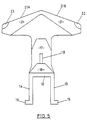
- thin bracing rib 18 Following in the plane of supporting rib 11 is thin bracing rib 18 which joins shaped rib 17 to governing member 19 which is as shown in Figure 5 shaped as a trapezium.
- shaped rib 17 has a substantially trapezium shaped head which in use is covered by previously described shaped member 20, shaped member 20 having therein a correspondingly shaped receiving region to allow shaped member 20 to partially cover the trapezium shaped head of shaped rib 17.
- plate 10 is connected to member 21.
- Member 21 has corner recesses 22 and 23 provided to accept corners 24 and 25 respectively of connecting member 6.
- Member 21 also has moulded therein downward extending V shaped raised area 27 and upward extending V shaped raised area 28. V shaped areas 27 and 28 provide an open channel between plate 10 and member 21. Guiding surfaces 21A and 21B are also provided on member 21.
- the previously described article receptacle means and just described tri-state mounting means comprise two independent pieces of the present invention. These two pieces are connected together by pivot member 30 which may be seen in Figures 1, 3 and 4.
- Pivot member 30 is of a substantially U shape and is preferably constructed from a light yet strong metal or plastics material. Ends 31 and 32 of pivot member 30 pass through holes in arm members 4 and 5 respectively. Pivot member 30 is thus rotatable about an axis through said holes in arm members 4 and 5.
- the U shaped pivot member 30 is further passed through the open channel between V shaped areas 27 and 28 in member 21 and is free to move both in a plane parallel to the member 21 as well as being rotatable in that plane around the pivot formed by the intersection of upper extending V shaped area 28 in connecting member 6 and pivot member 30.
- the apparatus of the present invention is connected to a conveyor system which preferably comprises an endless chain.
- the present invention is attached to the chain by placing side walls 13 and 14 of the coupling means astride one link in the chain so that the holes in side walls 13 and 14 may be used to pass dowels which also pass through corresponding holes in the link.
- a series of carriers may be attached to the chain so as to build up an endless series.
- a number of adjacent chains may be used in a gading/sorting/packaging operation with each carrier being independently operable.
- a controller which may comprise a computer, controls the operation of the grading/sorting/packaging system, which could either include weighing or imaging to size the fruit.
- the normal operating position of the present invention is with pivot member 30 resting on upward extending V shaped area 28 with corners 25 and 26 of connecting member 6 sitting in recesses 22 and 23 respectively of member 21.
- produce for example, fruit
- a section at the beginning of the conveyor system may be used as a "singulator" which has the purpose of ensuring that only one apple is carried by each carrier.
- This function may be carried out by causing roller 2 be raised and to rotate in a predetermined direction which has been found to have the desired effect of ejecting superfluous fruit.
- the fruit is at this stage supported between the rollers of consecutive carriers.
- the ejected fruit are then recycled or moved to a following empty cup.
- a video camera could then be used to analyze the fruit.
- the rollers 2 could then be rotated so that multiple views of the fruit could be taken, this is especially important for produce with a non-spherical shape.
- the cups are then passed over a weighing section which preferably comprises load cells used to determine the weights of each individual piece of fruit.
- a weighing section which preferably comprises load cells used to determine the weights of each individual piece of fruit.
- the extending arms 8 and 9 are guided onto a load sensing section where the article receptacle means are lifted from their resting place on the tri-state mounting means by an upward force applied to weight points 33 below each of extending wings 8 and 9.
- the article receptacle means are pivotable in a vertical plane by the action of pivot member 30 against V shaped areas 27 and 28 and is able to substantially "float" in this vertical plane for weighing purposes.
- the article receptacle means is then substantially free from the effects of the conveyor system (that is free from vibration and the weight of the chain) and the contents of the cup may then be weighed.
- the roller 2 may be removed from the article receptacle means.
- the vertical height of the carrier would be substantially reduced.
- a shaped plate cup could be used in the place of the roller which could be an extension of back plate 7, the cup being connected to the tri-state mounting means and having the ability to tip as will soon be described. It may be preferable to omit the roller 2 in systems where the item to be carried would produce a residue capable of becoming lodged in parts of the roller mechanism possibly increasing fatigue or promoting ill health (for example, chicken pieces).
- the control system controlling the operation decides where each piece is to be sent so that each piece may be ejected from the cup at the desired place along the conveyor. This is accomplished by providing an upward tipping force to the underside of either of extending wings 8 or 9 (depending which direction the carrier is to be tipped). This force is applied, for example, by computer controlled solenoid rams. The fruit is ejected to the side opposite that which the upward tipping force was applied, perpendicular to the direction of travel. It has been found that the design of the present invention has resulted in stability in its normal operating position.
- Extending wings 8 or 9 guide the contents from the carrier, reducing bruising in the case of sensitive contents.
- corners 25 or 26 are caused to slip from their temporarily stable positions in recesses 22 and 23 respectively along guiding surfaces 21A or 21B.
- the loose coupling between shaped rib 17 and shaped member 6 slips upon tipping and pivot member 30 slides and rotates in the plane of plate 10 in response to the weight of the article receptacle means moving position.
- This sliding action means that the contents of the carrier are shifted sideways rather than being dropped.
- the carrier is restrained to only tip as far as governing member 19 will allow before roller 2 contacts governing member 19.
- the carrier is returned to its upright position once the conveyor system returns the carrier to the point where they are filled. Usually this is accomplished by a section wherein the carrier is transported upside down. Upon returning to their upright positions, the cups may be guided so that the article receptacle means once again sits in its temporary stable position on the tri-state mounting means as previously described.
- the present invention by having the ability to tip the contents to either side of the conveyor system is expected to increase the efficiency of grading/packing/sorting lines by allowing greater flexibility. Also, the present invention is compatible with both imaging systems (because the roller rotates the fruit to give multiple views) and weighing systems (because the carrier is stable with minimum external forces). By unloading to both sides of a conveyor, it is possible to have more unloading points in a given length of conveyor. As the contents of the carriers of the present invention are shifted sideways rather than being "kicked” or dropped, improvements in fruit quality are expected as well as less wastage, formerly due to rough handling. The present invention is designed for use with many currently installed systems and so should be easily accepted without major conversions required. Also, the present invention, by incorporating a rotatable roller does away with the need to provide a section of conveyor to be used as a "singulator".
Landscapes
- Engineering & Computer Science (AREA)
- Mechanical Engineering (AREA)
- Sorting Of Articles (AREA)
- Vending Machines For Individual Products (AREA)
- Geophysics And Detection Of Objects (AREA)
- Analysing Materials By The Use Of Radiation (AREA)
- Rollers For Roller Conveyors For Transfer (AREA)
- Stacking Of Articles And Auxiliary Devices (AREA)
- Structure Of Belt Conveyors (AREA)
- Discharge Of Articles From Conveyors (AREA)
- Auxiliary Devices For And Details Of Packaging Control (AREA)
Claims (8)
- Ein Artikel-Trägermittel (1) für eine Artikelklassifizierungs-Vorrichtung mit endlosem Förderband, wobei das Trägermittel (1) umfasst, ein Förderband-Eingriffsmittel (13, 14), Aufnabmemittel für Artikel (7, 2) und ein Drei-Zustands-Halterungsmittel (10, 11, 13, 14, 21), das das Aufnahmemittel für Artikel (1) mit dem Förderband-Eingriffsmittel (13, 14) verbindet und normalerweise das Aufnabmemittel für Artikel (7, 2) in einer horizontalen Ebene hält, es aber dazu veranlasst, den darin enthaltenen Artikel zu der einen oder anderen Seite zu entladen, dadurch gekennzeichnet, dass das Aufnahmemittel für Artikel (7, 2) mit dem Drei-Zustands-Halterungsmittel (10, 11, 13, 14, 21) über eine Verbindung (27, 28, 30) verbunden ist, die ein begrenztes seitliches Kippen aus seiner Position in der horizontalen Ebene erlaubt; und dadurch, dass eine Kopplung (17, 20) zwischen dem Aufnabmemittel für Artikel (7, 2) und dem Drei-Zustands-Halterungsmittel besteht, wobei diese Kopplung normalerweise das Aufnahmemittel für Artikel in der Position in der horizontalen Ebene hält, aber in der Lage ist, das Aufnahmemittel für Artikel als Reaktion auf eine äußere Kraft freizugeben, um es zu ermöglichen, dass das Aufnähmemittel für Artikel (1) zur Seite gleitet und zu einer der Seiten des Drei-Zustands-Halterungsmittels fällt, um dadurch, abhängig davon, auf welche Seite des Aufnahmemittels für Artikel die Kraft aufgebracht wird, jeglichen darin gehaltenen Artikel zu entladen.
- Artikel-Trägermittel nach Anspruch 1, dadurch gekennzeichnet, dass das Drei-Zustands-Halterungsmittel (21) weiterhin horizontale Positionshaltemittel (22, 23) einschließt, die es erlauben, dass das Aufnahmemittel für Artikel (1, 2) in der horizontalen Ebene gehalten wird.
- Artikel-Trägermittel nach Anspruch 1 oder Anspruch 2, dadurch gekennzeichnet, dass die Verbindung zwischen dem Aufnahmemittel für Artikel (7, 2) und dem Drei-Zustands-Halterungsmittel verschiebbare Schwenkmittel (30) umfasst, die das Drei-Zustands-Halterungsmittel (21) an das Aufnahmemittel für Artikel (7, 2) koppeln, um das Drei-Zustands-Halterungsmittel (21) beim Halten des Aufnahmemittels für Artikel (7, 2) zu unterstützen.
- Artikel-Trägermittel nach einem der Ansprüche 1 bis 3, dadurch gekennzeichnet, dass das Drei-Zustands-Halterungsmittel (21) auch verschiebbare Führungsmittel (21A, 21B) einschließt, um das Aufnahmemittel für Artikel (1) zu führen, während es aus der normalen horizontalen Ebene fällt.
- Artikel-Trägermittel nach einem der vorstehenden Ansprüche, dadurch gekennzeichnet, dass das Aufnahmemittel für Artikel (7, 2) weiterhin einen U-förmigen Bügel (4, 5, 6) aufweist, der zwei herausragende Schenkel (4, 5) mit einer dazwischen angeordneten drehbaren, profilierten Rolle (2) und eine Rückplatte (7), die parallel zu der Achse der profilierten Rolle (2) angeordnet ist, umfasst, wobei die profilierte Rolle (2) und die Rückplatte (7) einen Napf zur Aufnahme von Artikeln bilden.
- Artikel-Trägermittel nach Anspruch 5, dadurch gekennzeichnet, dass die profilierte Rolle eine konkave Oberfläche aufweist, d.h. dass der Durchmesser der Rolle (2) in der Mitte am schmalsten ist und zu den Enden der Rolle (2) zunimmt, um einen Teil des Napfes (2, 7) zu bilden.
- Artikel-Trägermittel nach Anspruch 5 oder Anspruch 6, dadurch gekennzeichnet, dass die herausragenden Schenkel (4, 5) des U-förmigen Bügels (4, 5, 6) jeweils mit sich transversal erstreckenden Flügeln (8, 9) ausgestattet sind, um der äußeren Kraft einen Kontaktbereich zu liefern und es zu ermöglichen, den U-förmigen Bügel (4, 5, 6) von dem Führungsmittel durch Anheben der beiden herausragenden Flügel (8, 9) anzuheben, um es zu ermöglichen, eine Wägefunktion durchführen zu können.
- Artikel-Trägermittel nach Anspruch 7, dadurch gekennzeichnet, dass die herausragenden Hügel (8, 9) so geformt sind, dass der Inhalt des Aufnahmemittels für Artikel (7, 2) durch diese geführt werden kann.
Priority Applications (3)
| Application Number | Priority Date | Filing Date | Title |
|---|---|---|---|
| EP97113197A EP0808785B1 (de) | 1992-12-22 | 1993-12-16 | Einrichtung zur Kalibrierung von Artikeln |
| ES97113197T ES2137749T3 (es) | 1992-12-22 | 1993-12-16 | Aparato de calibrado de articulos. |
| GR990403296T GR3032209T3 (en) | 1992-12-22 | 1999-12-21 | Article grading apparatus |
Applications Claiming Priority (3)
| Application Number | Priority Date | Filing Date | Title |
|---|---|---|---|
| NZ24556792 | 1992-12-22 | ||
| NZ24556792 | 1992-12-22 | ||
| PCT/NZ1993/000126 WO1994014547A1 (en) | 1992-12-22 | 1993-12-16 | Article grading apparatus |
Related Child Applications (1)
| Application Number | Title | Priority Date | Filing Date |
|---|---|---|---|
| EP97113197A Division EP0808785B1 (de) | 1992-12-22 | 1993-12-16 | Einrichtung zur Kalibrierung von Artikeln |
Publications (3)
| Publication Number | Publication Date |
|---|---|
| EP0675768A1 EP0675768A1 (de) | 1995-10-11 |
| EP0675768A4 EP0675768A4 (de) | 1996-06-05 |
| EP0675768B1 true EP0675768B1 (de) | 2000-09-13 |
Family
ID=19924227
Family Applications (2)
| Application Number | Title | Priority Date | Filing Date |
|---|---|---|---|
| EP97113197A Expired - Lifetime EP0808785B1 (de) | 1992-12-22 | 1993-12-16 | Einrichtung zur Kalibrierung von Artikeln |
| EP94902140A Expired - Lifetime EP0675768B1 (de) | 1992-12-22 | 1993-12-16 | Vorrichtung zur klassifizierung von artikeln |
Family Applications Before (1)
| Application Number | Title | Priority Date | Filing Date |
|---|---|---|---|
| EP97113197A Expired - Lifetime EP0808785B1 (de) | 1992-12-22 | 1993-12-16 | Einrichtung zur Kalibrierung von Artikeln |
Country Status (11)
| Country | Link |
|---|---|
| US (1) | US6003653A (de) |
| EP (2) | EP0808785B1 (de) |
| JP (1) | JPH08504729A (de) |
| AT (2) | ATE196265T1 (de) |
| AU (2) | AU687024B2 (de) |
| BR (1) | BR9307731A (de) |
| DE (2) | DE69329426T2 (de) |
| ES (2) | ES2137749T3 (de) |
| GR (2) | GR3032209T3 (de) |
| NZ (2) | NZ258653A (de) |
| WO (1) | WO1994014547A1 (de) |
Families Citing this family (10)
| Publication number | Priority date | Publication date | Assignee | Title |
|---|---|---|---|---|
| AU701354B2 (en) * | 1996-09-13 | 1999-01-28 | Geoffrey William Payne | Conveying cup assembly for a fruit handling equipment |
| NZ523931A (en) | 2003-01-31 | 2005-06-24 | Anzpac Systems Ltd | Article carrier for a grading apparatus |
| CN1867412B (zh) * | 2003-10-09 | 2010-08-25 | Fps食品加工系统公司 | 用于分拣设备的托架 |
| NL2003516C2 (nl) * | 2009-09-21 | 2011-03-22 | Greefs Wagen Carrosserie | Transportinrichting voor het transporteren van een product, en sorteerinrichting en werkwijze daarvoor. |
| US20150145678A1 (en) * | 2012-03-29 | 2015-05-28 | Red Bull Gmbh | Computer Network for Monitoring and Controlling Storage Facilities Comprising a Load State Device and a User Detection Device |
| CN102616527A (zh) * | 2012-04-01 | 2012-08-01 | 无锡大东机械制造有限公司 | 一种袋装箱装物品提升输送机 |
| US9527113B2 (en) | 2012-11-08 | 2016-12-27 | Compac Technologies Limited | Article carrier for a grading apparatus |
| CN110023211B (zh) * | 2016-07-01 | 2021-06-29 | 康派克科技有限公司 | 传送机系统及其物品运载装置 |
| CN109834057A (zh) * | 2019-03-22 | 2019-06-04 | 平度市林焱精密机械厂 | 一种水果分拣传送车 |
| CN113479567B (zh) * | 2021-07-14 | 2022-05-20 | 浙江大学 | 一种用于果蔬分选的滚轮式输送装置 |
Family Cites Families (22)
| Publication number | Priority date | Publication date | Assignee | Title |
|---|---|---|---|---|
| US3747755A (en) * | 1971-12-27 | 1973-07-24 | Massachusetts Inst Technology | Apparatus for determining diffuse and specular reflections of infrared radiation from a sample to classify that sample |
| SU447328A1 (ru) * | 1972-12-02 | 1974-10-25 | Предприятие П/Я А-1944 | Распределительный тележечный конвейер |
| US4262807A (en) * | 1978-11-24 | 1981-04-21 | Durand-Wayland, Inc. | Process and apparatus for weighing and sorting articles |
| JPS5719221A (en) * | 1980-07-09 | 1982-02-01 | Maki Seisakusho:Kk | Classifying bucket for fruit, vegetables and the like |
| JPS5719222A (en) * | 1980-07-09 | 1982-02-01 | Maki Seisakusho:Kk | Discharging device for bucket conveyor type classfier for fruit, vegetables and the like |
| JPS5719074A (en) * | 1980-07-09 | 1982-02-01 | Maki Mfg Co Ltd | Weight selecting method for fruit, vegetable, etc. |
| US4403669A (en) * | 1982-01-18 | 1983-09-13 | Eshet Eilon | Apparatus for weighing continuously-moving articles particularly useful for grading produce |
| JPS58135026A (ja) * | 1982-02-02 | 1983-08-11 | Maki Seisakusho:Kk | コンベア装置 |
| IT1198074B (it) * | 1986-11-10 | 1988-12-21 | Francesco Canziani | Apparecchiatura smistatrice con i dispositivi di trasporto degli oggetti da smistare preposizionabili in funzione della destinazione di scarico |
| EP0267790A3 (de) * | 1986-11-12 | 1990-01-17 | Lockwood Graders (U.K.) Limited | Verfahren und Vorrichtung zum Sortieren von Gegenständen |
| US4787498A (en) * | 1988-02-10 | 1988-11-29 | Babcock Industries Inc. | Tire handling tray sortation system |
| US5497887A (en) * | 1988-03-15 | 1996-03-12 | Autoline, Inc. | Method and apparatus for handling objects |
| ZA894074B (en) * | 1988-05-31 | 1990-04-20 | Aaron James Warkentin | Off-loading conveying system. |
| US5044504A (en) * | 1988-09-23 | 1991-09-03 | Powell Machinery Inc. | Self-singulating weight sizer |
| JPH02169409A (ja) * | 1989-11-24 | 1990-06-29 | Maki Seisakusho:Kk | バケットコンベア式選別機のバケット |
| FR2670691B1 (fr) * | 1990-12-19 | 1993-03-19 | Materiel Arboriculture | Dispositif de convoyage de produits, notamment de fruits, adapte pour effectuer un triage desdits produits en fonction de criteres de selection predetermines. |
| ZA922828B (en) * | 1991-04-18 | 1992-12-30 | Autoline Inc | Apparatus and method for sorting objects |
| US5244100A (en) * | 1991-04-18 | 1993-09-14 | Regier Robert D | Apparatus and method for sorting objects |
| WO1993007972A1 (en) * | 1991-10-15 | 1993-04-29 | Colour Vision Systems Pty. Ltd. | Conveying system for foodstuffs |
| DE59207764D1 (de) * | 1991-10-29 | 1997-02-06 | Grapha Holding Ag | Anlage zur Sortieren von Stückgütern |
| US5267654A (en) * | 1992-05-26 | 1993-12-07 | Durand-Wayland, Inc. | Article-holding cup and sorting apparatus |
| CH685491A5 (de) * | 1992-07-30 | 1995-07-31 | Daverio Ag | Wagen eines Förderers für Stückgüter. |
-
1993
- 1993-12-16 EP EP97113197A patent/EP0808785B1/de not_active Expired - Lifetime
- 1993-12-16 DE DE69329426T patent/DE69329426T2/de not_active Expired - Lifetime
- 1993-12-16 JP JP6515050A patent/JPH08504729A/ja active Pending
- 1993-12-16 WO PCT/NZ1993/000126 patent/WO1994014547A1/en not_active Ceased
- 1993-12-16 US US08/464,647 patent/US6003653A/en not_active Expired - Lifetime
- 1993-12-16 BR BR9307731-9A patent/BR9307731A/pt not_active IP Right Cessation
- 1993-12-16 DE DE69326565T patent/DE69326565T2/de not_active Expired - Lifetime
- 1993-12-16 AT AT94902140T patent/ATE196265T1/de not_active IP Right Cessation
- 1993-12-16 NZ NZ258653A patent/NZ258653A/en not_active IP Right Cessation
- 1993-12-16 EP EP94902140A patent/EP0675768B1/de not_active Expired - Lifetime
- 1993-12-16 AU AU56614/94A patent/AU687024B2/en not_active Expired
- 1993-12-16 AT AT97113197T patent/ATE184855T1/de not_active IP Right Cessation
- 1993-12-16 ES ES97113197T patent/ES2137749T3/es not_active Expired - Lifetime
- 1993-12-16 NZ NZ314466A patent/NZ314466A/en not_active IP Right Cessation
- 1993-12-16 ES ES94902140T patent/ES2152301T3/es not_active Expired - Lifetime
-
1997
- 1997-07-18 AU AU28712/97A patent/AU686537B2/en not_active Ceased
-
1999
- 1999-12-21 GR GR990403296T patent/GR3032209T3/el unknown
-
2000
- 2000-12-12 GR GR20000402740T patent/GR3035052T3/el unknown
Also Published As
| Publication number | Publication date |
|---|---|
| WO1994014547A1 (en) | 1994-07-07 |
| NZ314466A (en) | 1997-05-26 |
| DE69326565D1 (de) | 1999-10-28 |
| ES2152301T3 (es) | 2001-02-01 |
| AU687024B2 (en) | 1998-02-19 |
| US6003653A (en) | 1999-12-21 |
| JPH08504729A (ja) | 1996-05-21 |
| AU2871297A (en) | 1997-09-25 |
| NZ258653A (en) | 1997-05-26 |
| EP0675768A1 (de) | 1995-10-11 |
| ATE196265T1 (de) | 2000-09-15 |
| EP0808785B1 (de) | 1999-09-22 |
| EP0675768A4 (de) | 1996-06-05 |
| DE69326565T2 (de) | 2000-03-09 |
| AU5661494A (en) | 1994-07-19 |
| ATE184855T1 (de) | 1999-10-15 |
| AU686537B2 (en) | 1998-02-05 |
| BR9307731A (pt) | 1999-08-31 |
| GR3032209T3 (en) | 2000-04-27 |
| GR3035052T3 (en) | 2001-03-30 |
| EP0808785A1 (de) | 1997-11-26 |
| DE69329426T2 (de) | 2001-03-29 |
| DE69329426D1 (de) | 2000-10-19 |
| ES2137749T3 (es) | 1999-12-16 |
Similar Documents
| Publication | Publication Date | Title |
|---|---|---|
| CA2108572C (en) | Apparatus and method for sorting objects | |
| US5497887A (en) | Method and apparatus for handling objects | |
| US5244100A (en) | Apparatus and method for sorting objects | |
| JP2587663B2 (ja) | 物品を自動的に分類および分配する装置 | |
| EP1226408B1 (de) | Sortiervorrichtung | |
| US4957619A (en) | Self-singulating weight sizer | |
| US5294004A (en) | Article-holding cup and scale for apparatus that sorts articles by weight | |
| AU687024B2 (en) | Article grading apparatus | |
| US12496620B2 (en) | Fruit sorting equipment | |
| US4413690A (en) | Weighing cup | |
| US6092640A (en) | Article grading apparatus | |
| US5044504A (en) | Self-singulating weight sizer | |
| US20250042673A1 (en) | Apparatus and methods relating to sorting objects | |
| JPH02169409A (ja) | バケットコンベア式選別機のバケット | |
| AU628043C (en) | Method and apparatus for handling and sorting objects | |
| CA3249592A1 (en) | TRANSPORT DEVICE |
Legal Events
| Date | Code | Title | Description |
|---|---|---|---|
| PUAI | Public reference made under article 153(3) epc to a published international application that has entered the european phase |
Free format text: ORIGINAL CODE: 0009012 |
|
| 17P | Request for examination filed |
Effective date: 19950711 |
|
| AK | Designated contracting states |
Kind code of ref document: A1 Designated state(s): AT BE CH DE DK ES FR GB GR IE IT LI LU MC NL PT SE |
|
| A4 | Supplementary search report drawn up and despatched |
Effective date: 19960418 |
|
| AK | Designated contracting states |
Kind code of ref document: A4 Designated state(s): AT BE CH DE DK ES FR GB GR IE IT LI LU MC NL PT SE |
|
| RAP1 | Party data changed (applicant data changed or rights of an application transferred) |
Owner name: HORTICULTURAL AUTOMATION LIMITED |
|
| 17Q | First examination report despatched |
Effective date: 19980302 |
|
| GRAG | Despatch of communication of intention to grant |
Free format text: ORIGINAL CODE: EPIDOS AGRA |
|
| GRAG | Despatch of communication of intention to grant |
Free format text: ORIGINAL CODE: EPIDOS AGRA |
|
| GRAG | Despatch of communication of intention to grant |
Free format text: ORIGINAL CODE: EPIDOS AGRA |
|
| GRAG | Despatch of communication of intention to grant |
Free format text: ORIGINAL CODE: EPIDOS AGRA |
|
| GRAH | Despatch of communication of intention to grant a patent |
Free format text: ORIGINAL CODE: EPIDOS IGRA |
|
| GRAH | Despatch of communication of intention to grant a patent |
Free format text: ORIGINAL CODE: EPIDOS IGRA |
|
| GRAA | (expected) grant |
Free format text: ORIGINAL CODE: 0009210 |
|
| AK | Designated contracting states |
Kind code of ref document: B1 Designated state(s): AT BE CH DE DK ES FR GB GR IE IT LI LU MC NL PT SE |
|
| DX | Miscellaneous (deleted) | ||
| PG25 | Lapsed in a contracting state [announced via postgrant information from national office to epo] |
Ref country code: LI Free format text: LAPSE BECAUSE OF FAILURE TO SUBMIT A TRANSLATION OF THE DESCRIPTION OR TO PAY THE FEE WITHIN THE PRESCRIBED TIME-LIMIT Effective date: 20000913 Ref country code: CH Free format text: LAPSE BECAUSE OF FAILURE TO SUBMIT A TRANSLATION OF THE DESCRIPTION OR TO PAY THE FEE WITHIN THE PRESCRIBED TIME-LIMIT Effective date: 20000913 Ref country code: BE Free format text: LAPSE BECAUSE OF FAILURE TO SUBMIT A TRANSLATION OF THE DESCRIPTION OR TO PAY THE FEE WITHIN THE PRESCRIBED TIME-LIMIT Effective date: 20000913 Ref country code: AT Free format text: LAPSE BECAUSE OF FAILURE TO SUBMIT A TRANSLATION OF THE DESCRIPTION OR TO PAY THE FEE WITHIN THE PRESCRIBED TIME-LIMIT Effective date: 20000913 |
|
| REF | Corresponds to: |
Ref document number: 196265 Country of ref document: AT Date of ref document: 20000915 Kind code of ref document: T |
|
| REG | Reference to a national code |
Ref country code: CH Ref legal event code: EP |
|
| REF | Corresponds to: |
Ref document number: 69329426 Country of ref document: DE Date of ref document: 20001019 |
|
| REG | Reference to a national code |
Ref country code: IE Ref legal event code: FG4D |
|
| ET | Fr: translation filed | ||
| ITF | It: translation for a ep patent filed | ||
| PG25 | Lapsed in a contracting state [announced via postgrant information from national office to epo] |
Ref country code: SE Free format text: LAPSE BECAUSE OF FAILURE TO SUBMIT A TRANSLATION OF THE DESCRIPTION OR TO PAY THE FEE WITHIN THE PRESCRIBED TIME-LIMIT Effective date: 20001213 Ref country code: PT Free format text: LAPSE BECAUSE OF FAILURE TO SUBMIT A TRANSLATION OF THE DESCRIPTION OR TO PAY THE FEE WITHIN THE PRESCRIBED TIME-LIMIT Effective date: 20001213 Ref country code: DK Free format text: LAPSE BECAUSE OF FAILURE TO SUBMIT A TRANSLATION OF THE DESCRIPTION OR TO PAY THE FEE WITHIN THE PRESCRIBED TIME-LIMIT Effective date: 20001213 |
|
| REG | Reference to a national code |
Ref country code: GB Ref legal event code: 727 |
|
| PG25 | Lapsed in a contracting state [announced via postgrant information from national office to epo] |
Ref country code: LU Free format text: LAPSE BECAUSE OF NON-PAYMENT OF DUE FEES Effective date: 20001216 |
|
| PG25 | Lapsed in a contracting state [announced via postgrant information from national office to epo] |
Ref country code: IE Free format text: LAPSE BECAUSE OF NON-PAYMENT OF DUE FEES Effective date: 20001218 |
|
| REG | Reference to a national code |
Ref country code: GB Ref legal event code: 727A |
|
| PG25 | Lapsed in a contracting state [announced via postgrant information from national office to epo] |
Ref country code: MC Free format text: THE PATENT HAS BEEN ANNULLED BY A DECISION OF A NATIONAL AUTHORITY Effective date: 20001231 |
|
| REG | Reference to a national code |
Ref country code: ES Ref legal event code: FG2A Ref document number: 2152301 Country of ref document: ES Kind code of ref document: T3 |
|
| REG | Reference to a national code |
Ref country code: CH Ref legal event code: PL |
|
| REG | Reference to a national code |
Ref country code: GB Ref legal event code: 727B |
|
| PLBE | No opposition filed within time limit |
Free format text: ORIGINAL CODE: 0009261 |
|
| STAA | Information on the status of an ep patent application or granted ep patent |
Free format text: STATUS: NO OPPOSITION FILED WITHIN TIME LIMIT |
|
| 26N | No opposition filed | ||
| REG | Reference to a national code |
Ref country code: IE Ref legal event code: MM4A |
|
| REG | Reference to a national code |
Ref country code: GB Ref legal event code: IF02 |
|
| REG | Reference to a national code |
Ref country code: GB Ref legal event code: 732E |
|
| NLS | Nl: assignments of ep-patents |
Owner name: ANZPAC SYSTEMS LIMITED |
|
| REG | Reference to a national code |
Ref country code: ES Ref legal event code: PC2A |
|
| REG | Reference to a national code |
Ref country code: FR Ref legal event code: TP |
|
| PGFP | Annual fee paid to national office [announced via postgrant information from national office to epo] |
Ref country code: GR Payment date: 20110429 Year of fee payment: 18 Ref country code: DE Payment date: 20110420 Year of fee payment: 18 |
|
| PGFP | Annual fee paid to national office [announced via postgrant information from national office to epo] |
Ref country code: ES Payment date: 20121227 Year of fee payment: 20 Ref country code: IT Payment date: 20121220 Year of fee payment: 20 Ref country code: GB Payment date: 20121212 Year of fee payment: 20 |
|
| PGFP | Annual fee paid to national office [announced via postgrant information from national office to epo] |
Ref country code: NL Payment date: 20121208 Year of fee payment: 20 Ref country code: FR Payment date: 20130107 Year of fee payment: 20 |
|
| REG | Reference to a national code |
Ref country code: GR Ref legal event code: ML Ref document number: 20000402740 Country of ref document: GR Effective date: 20130703 |
|
| REG | Reference to a national code |
Ref country code: DE Ref legal event code: R119 Ref document number: 69329426 Country of ref document: DE Effective date: 20130702 |
|
| PG25 | Lapsed in a contracting state [announced via postgrant information from national office to epo] |
Ref country code: GR Free format text: LAPSE BECAUSE OF NON-PAYMENT OF DUE FEES Effective date: 20130703 Ref country code: DE Free format text: LAPSE BECAUSE OF NON-PAYMENT OF DUE FEES Effective date: 20130702 |
|
| REG | Reference to a national code |
Ref country code: NL Ref legal event code: V4 Effective date: 20131216 |
|
| REG | Reference to a national code |
Ref country code: GB Ref legal event code: PE20 Expiry date: 20131215 |
|
| PG25 | Lapsed in a contracting state [announced via postgrant information from national office to epo] |
Ref country code: GB Free format text: LAPSE BECAUSE OF EXPIRATION OF PROTECTION Effective date: 20131215 |
|
| REG | Reference to a national code |
Ref country code: ES Ref legal event code: FD2A Effective date: 20140925 |
|
| PG25 | Lapsed in a contracting state [announced via postgrant information from national office to epo] |
Ref country code: ES Free format text: LAPSE BECAUSE OF EXPIRATION OF PROTECTION Effective date: 20131217 |