EP0675778B1 - Dispositif de transfert d'un courant electrique a partir d'une electrode a fil mobile et vers une electrode a fil mobile - Google Patents
Dispositif de transfert d'un courant electrique a partir d'une electrode a fil mobile et vers une electrode a fil mobile Download PDFInfo
- Publication number
- EP0675778B1 EP0675778B1 EP94905350A EP94905350A EP0675778B1 EP 0675778 B1 EP0675778 B1 EP 0675778B1 EP 94905350 A EP94905350 A EP 94905350A EP 94905350 A EP94905350 A EP 94905350A EP 0675778 B1 EP0675778 B1 EP 0675778B1
- Authority
- EP
- European Patent Office
- Prior art keywords
- wire
- rod
- conductive member
- longitudinal axis
- bore
- Prior art date
- Legal status (The legal status is an assumption and is not a legal conclusion. Google has not performed a legal analysis and makes no representation as to the accuracy of the status listed.)
- Expired - Lifetime
Links
- 230000001154 acute effect Effects 0.000 claims description 8
- 229910003460 diamond Inorganic materials 0.000 claims description 6
- 239000010432 diamond Substances 0.000 claims description 6
- 238000003466 welding Methods 0.000 claims description 5
- WFKWXMTUELFFGS-UHFFFAOYSA-N tungsten Chemical compound [W] WFKWXMTUELFFGS-UHFFFAOYSA-N 0.000 claims description 3
- 229910052721 tungsten Inorganic materials 0.000 claims description 3
- 239000010937 tungsten Substances 0.000 claims description 3
- 239000004020 conductor Substances 0.000 claims description 2
- 238000005520 cutting process Methods 0.000 description 2
- 238000012423 maintenance Methods 0.000 description 2
- 238000004519 manufacturing process Methods 0.000 description 2
- 239000000463 material Substances 0.000 description 2
- 229910052751 metal Inorganic materials 0.000 description 2
- 239000002184 metal Substances 0.000 description 2
- 230000000717 retained effect Effects 0.000 description 2
- 239000011324 bead Substances 0.000 description 1
- 230000007423 decrease Effects 0.000 description 1
- 230000003247 decreasing effect Effects 0.000 description 1
- 239000011261 inert gas Substances 0.000 description 1
- 238000003754 machining Methods 0.000 description 1
- 230000013011 mating Effects 0.000 description 1
- 238000000034 method Methods 0.000 description 1
- 239000012811 non-conductive material Substances 0.000 description 1
- 238000005096 rolling process Methods 0.000 description 1
- 238000007493 shaping process Methods 0.000 description 1
- UONOETXJSWQNOL-UHFFFAOYSA-N tungsten carbide Chemical compound [W+]#[C-] UONOETXJSWQNOL-UHFFFAOYSA-N 0.000 description 1
Images

Classifications
-
- B—PERFORMING OPERATIONS; TRANSPORTING
- B23—MACHINE TOOLS; METAL-WORKING NOT OTHERWISE PROVIDED FOR
- B23H—WORKING OF METAL BY THE ACTION OF A HIGH CONCENTRATION OF ELECTRIC CURRENT ON A WORKPIECE USING AN ELECTRODE WHICH TAKES THE PLACE OF A TOOL; SUCH WORKING COMBINED WITH OTHER FORMS OF WORKING OF METAL
- B23H7/00—Processes or apparatus applicable to both electrical discharge machining and electrochemical machining
- B23H7/02—Wire-cutting
- B23H7/08—Wire electrodes
- B23H7/10—Supporting, winding or electrical connection of wire-electrode
- B23H7/107—Current pickups
Definitions
- the present invention relates to the technical field of conveying electrical current between an electric current transfer element and an electrically conductive wire or cable which moves relative to the current transfer element. More specifically, the present invention relates to what are commonly referred to as "current pickups" which are connected to a power source and where the moving wire is caused to rub against the current pickup thus conveying alternating or direct electrical current or pulses either from the pickup to the wire or from the wire to the pickup.
- current pickups which are connected to a power source and where the moving wire is caused to rub against the current pickup thus conveying alternating or direct electrical current or pulses either from the pickup to the wire or from the wire to the pickup.
- Cylindrical or rod-shaped current pickups have also been used in several prior types of current conveying systems. With respect to such cylindrical/rod current pickups, the traveling wire is positioned and is caused to rub against the rod in a line perpendicular to the axis of the rod. Although a rod placed perpendicular to a moving wire is effective at conveying current, there are major drawbacks therewith. Unless the diameter of the rod is relatively large, the swept contact surface area of the rod is relatively small and the transfer of electrical current becomes inefficient while deformation of the wire is increased. In addition, the small contact surface provided by the perpendicular rod wears quickly thus requiring frequent maintenance to either adjust and provide a new contact surface or to replace the rod altogether. Further yet, increasing the perpendicular rod diameter to a sufficiently large size is undesirable because it is intrusive to other working elements of the system and prevents compact designs.
- the moving wire is caused to slide or rub against an electrically charged surface, thus, transferring the electrical current therethrough to and from the moving wire. Consequently, the surface finish and shape of the current pickup in the area where the wire rubs against the current pickup is critical because electrical current must be effectively transferred while minimizing damage and wear to the wire and current pickup.
- Some of the most effective contact surface shapes are curvilinear, such as, for example shown in U.S. Patent No. 4,896,013.
- the current pickup contact surface shapes are normally machined so as to achieve the correct curvature and surface finish. However, the machining operation is time-consuming and significantly increases the cost of the current pickups.
- the present invention overcomes the above-mentioned and other disadvantages associated with prior current pickups by providing a rod-shaped or cylindrical pickup at an acute angle with respect to the axis of the wire defined by two points.
- This axis or normal straight line of travel of the wire is offset so as to intersect the outer surface of the rod and cause the wire to rub thereagainst in a helical or elliptic contact pattern. Accordingly, although the rod diameter is circular and generally small, the contact surface appears elliptical to the wire along its contact length.
- Wire guide elements are provided at both ends of the rod and effectively define the axis of the traveling wire.
- the guide elements which can be pulleys, V-grooved components, hook-shaped components, orifice components, etc., and combinations thereof thus position the wire at an acute angle with respect to the rod and preferably, for maximizing the elliptic contact surface, place it at an angle of 5 to 20 degrees.
- the present invention overcomes the disadvantages associated with prior current pickups by providing an electrically conductive member such as a rod having a circular outer surface with respect to its longitudinal axis.
- the rod is received within a bore of a rod holder body.
- the rod holder body includes a wire receiving hole therethrough at an acute angle from the rod and bore longitudinal axes.
- the wire receiving hole surface and the bore surface intersect and thereby define a generally straight elongate passage therebetween.
- the electrically conductive wire to which electrical current is transferred is received through the wire hole and is guided therethrough with two orifice type guide members, one on each side of the wire hole.
- the passage between the wire hole and the bore is generally parallel to a straight line defined between the guide member bores.
- This straight line also intersects the electrically conductive rod circular outer surface so that when wire traveling through the two guide bores is made taut, the wire contacts the rod circular outer contact surface along a curvilinear path or, more specifically, along a path defined by a segment of an ellipse.
- the angle between the rod longitudinal axis and the straight line defined between the guide members, the offset of the straight line for intersecting the rod outer surface and the rod material can be varied so that in any particular situation, given the wire type, speed, voltage, current, etc., the electrical transfer efficiency may be maximized while minimizing wear on the wire and rod.
- the angle between the rod longitudinal axis and the straight line between the guide members decreases, the segment of an ellipse defined by the contact surface opens and becomes wider.
- increasing the angle towards 90 degrees closes the ellipse segment until, at 90 degrees, the contact surface becomes circular.
- the rod is placed at an angle between 5 degrees and 20 degrees.
- the rod holder body can be made of a non-electrically conductive material while the rod is preferably made of tungsten.
- the guide members are preferably the orifice type and are made of diamond.
- the holder body wire hole increases in diameter away from the rod and toward the guide members to accommodate threading of the wire through the wire hole.
- One end of the rod includes a tool receiving recess or slot for receiving a tool and turning the rod about its longitudinal axis.
- a tool receiving recess or slot for receiving a tool and turning the rod about its longitudinal axis.
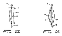
- Various shapes having a circular outer surface with respect to the longitudinal axis are contemplated for use as conductive current pickup members. Some of these shapes are, in addition to the rod and cylindrical shapes, conical, convex, concave and double cones. As with the rod shape, a longitudinal bore can be provided through the conical, convex, concave and double cone shape current pickup members.
- the electrically conductive rod or other shape member is not received within a bore of a rod holder body but, rather, is pivotally connected at one or both of its longitudinal ends so as to rotate about its longitudinal axis.
- the conductive member is retained in position at an angle with respect to the normal straight line of wire travel by these pivotal connections rather than the bore inner surface such as with respect to the rod embodiment discussed hereinabove.
- the present invention is directed to an apparatus for transferring electrical current to a moving electrically conductive wire traveling between two points.
- the apparatus includes an electrically conductive member having a circular outer surface with respect to its longitudinal axis.
- the rod is located with its longitudinal axis at an acute angle from a straight line defined by the two points and with the circular outer surface in contact with the moving wire.
- the wire contacts the circular outer contact surface along a curvilinear path.
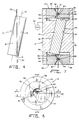
- Apparatus 12 includes an electrically conductive member or rod 14 having a longitudinal axis 16 and a generally circular outer surface 18.
- Rod 14 is preferably made of tungsten or tungsten carbide and the circular outer surface 18 is generally smooth.
- Rod 14 can be manufactured by a machine operation or by merely cutting pieces from a longer rod previously formed by rolling, drawing, or other manufacturing processes.
- the electrically conductive wire 10 is caused to travel between two points 20 defining a straight line therebetween.
- This straight line also referred to as the normal straight line of wire travel, is the path followed by wire 10 when taut and not obstructed in any manner.
- Wire 10 is caused to travel in this straight line between points 20 through the use of two guide members generally indicated as 22.
- Guide members 22 are preferably made with a diamond portion 24 through which there is a hole or bore 26. Bore 26 is preferably only slightly larger than the diameter of wire 10 for accurate guiding.
- the normal straight line of wire travel in practice, is the path of wire 10 when traveling between diamond portions 24 through bores 26 and when wire 10 is taut and unobstructed.
- points 20 are located at the center of bores 26.
- Diamond portions 24 of guide members 22 are mounted in a known and customary manner in guide barrels 28, normally made of sintered or other type of metal.
- Guide barrels 28 include frusto-conical entries 30 on both sides of diamond portions 24 and converging toward bores 26. Frusto-conical entries 30 are provided for aiding the threading of wire 10 through bores 26.
- Guide barrels 28 are affixed or otherwise connected to a rod holder body 32 in a known and customary manner, such as by providing corresponding mating threads in rod holder counter bore walls 34 and guide barrel circumferential wall 36 (not shown) and merely screwing guide barrels 28 into counter bores 38 of rod holder body 32.
- a wire receiving hole 40 having a wire hole surface 42 is provided generally through the central area of rod holder body 32. As shown in Figs. 5 and 6, wire 10 travels through wire hole 40.
- Rod receiving bore 44, having a rod bore surface 46 is also provided in rod holder body 32.
- Rod receiving bore 44 also has a longitudinal axis (not specifically depicted in the drawings) which is generally colinear with rod longitudinal axis 16 when rod 14 is received therein as shown in Figs. 5 and 6.
- Rod longitudinal axis 16 and thus also the longitudinal axis of bore 44 is at an acute angle from the normal straight line of wire travel.
- Bore 46 and wire hole 40 intersect or, more specifically, the rod bore surface 46 and the wire hole surface 42 intersect and thereby define a generally straight elongate passage 48 therebetween. It is noted that passage 48 is coplanar with a plane defined by line 6--6 shown in Fig. 5 and being parallel with the normal straight line of wire travel.
- Pulsed electrical current is normally provided to and from rod 14 from a pulsed or other type of power source 50 connected to rod holder body 32 which is itself conductive and effectively transfers the current to rod 14.
- rod holder body may be made of a non-conductive material and, in such an embodiment, the power source 50 would be connected directly to rod 14 for ultimately transferring current to and from moving wire electrode 20.
- wire hole 40 at each end thereof, is increasing in diameter in the direction away from the contact surface and towards guide members 22. More specifically, frusto conical portions 52 are provided at each end of wire hole 40. Frusto conical portions 52 aid in the threading of wire 10 from a guide member 22 and into wire hole 40.
- one end of rod 14 is provided with a tool receiving recess or slot 54 which is adapted to receive a flat screwdriver or some other suitable similar tool. Accordingly, by inserting a tool within slot 54, rod 14 can be turned about its longitudinal axis 16. In this fashion, as one curvilinear path contact surface is worn, the operator merely turns rod 14 a short radial distance for exposing an unworn portion of the rod outer surface and, thus, providing a brand new unworn surface. This process of exposing unworn portions of the rod outer surface may be repeated until all or substantially all of the rod outer surface 18 is worn beyond effective use and at such time the worn rod is removed from holder 32 and replaced by a new rod.
- the tool receiving recess slot 54 can be replaced by many different tool receiving shapes for providing the necessary turning force with a tool and turning rod 14 about its longitudinal axis.
- a rod or cylindrical shaped electrically conductive member 14 for providing a contact surface with the wire.
- rod 14 is retained within rod receiving bore 44 and is turned therein about its longitudinal axis for exposing unworn surfaces.
- a cylindrical rod 14 includes a bore 64 therethrough and further includes end bearing caps 66 at each end thereof. End bearing caps 66 are received within recesses (not shown) of a holding body 68 and, thus, rod or cylindrical member 14 is free to pivot about its longitudinal axis 16.
- longitudinal axis 16 is at an acute angle with respect to the normal straight line of wire travel and the contact surface between wire 20 and the circular outer surface 18 appears curvilinear or as a segment of an ellipse to the wire along its contact length.
- a means for turning the rod or cylindrical member about its longitudinal axis similar to that discussed hereinabove is contemplated and may be employed with this embodiment.
- Figs. 10a-10e there is depicted a rod shape with a longitudinal bore (cylindrical).
- Fig. 10b shows a conical outer surface;
- Fig. 10c shows a convex outer surface;
- Fig. 10d shows a concave outer surface; and
- Fig. 10e shows a double cone outer surface.
- the outer surface is circular with respect to the longitudinal axis. More specifically, with all of these shapes, a plane perpendicular to the longitudinal axis and intersecting the conductive member creates a circular shape.
- the conductive members of Figs. 10b-10e can also be provided with a longitudinal bore for pivotal mounting as shown in the embodiment of Fig. 9 and, also for decreasing the amount of material needed in forming the conductive member. It is noted that the outer surface 18 of all of these shapes forming a current conductive member 14, except for that of Fig. 10e, provides a contact surface for the wire 10 that is curvilinear and, more specifically, helical shaped.
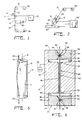
- apparatus 12 may be utilized for transferring electrical current to a moving wire used in at least electrical discharge machines as diagrammatically depicted in Fig. 1 and welding machines as diagrammatically depicted in Fig. 2.
- electrical discharge machines electrical current is placed on wire 10 as it is unwound from spool 56 and discarded or again wound on spool 58.
- Current of opposite polarity is placed on workpiece 60 from power source 50 and, thus, sparks caused between wire 10 and workpiece 60, as wire 10 is moved thereover, causes workpiece 60 to be selectively cut and shaped.
- a second current pickup can also be used below the workpiece (not shown) for yet more effectively conveying current between the wire 10 and current pickup rods 14.
- wire electrode 10 is generally defaced during use in cutting or shaping workpiece 60.
- Apparatus 12 can, for example, be used in metal inert gas (mig) welding machines.
Landscapes
- Chemical & Material Sciences (AREA)
- Chemical Kinetics & Catalysis (AREA)
- Electrochemistry (AREA)
- Engineering & Computer Science (AREA)
- Mechanical Engineering (AREA)
- Electrical Discharge Machining, Electrochemical Machining, And Combined Machining (AREA)
- Current-Collector Devices For Electrically Propelled Vehicles (AREA)
Claims (19)
- Dispositif de transfert de courant électrique vers et à partir d'un fil électriquement conducteur en mouvement (10) qui court entre deux points (20), ce dispositif étant caractérisé en ce que
il est prévu un élément électriquement conducteur (14) comportant un axe longitudinal (16), cet élément présentant une surface externe (18) qui est circulaire par rapport à l'axe longitudinal (16) et disposée avec l'axe longitudinal faisant un angle aigu avec une ligne droite définie par deux points (20), la surface externe circulaire (18) étant en contact avec le fil en mouvement (10), de sorte que le fil soit en contact avec la surface externe circulaire (18) le long d'un chemin courbe. - Dispositif selon la revendication 1, dans lequel l'élément conducteur (14) est utilisé dans une machine d'étincelage pour amener du courant à une électrode à fil en mouvement.
- Dispositif selon la revendication 1, dans lequel l'élément conducteur (14) est utilisé dans une machine à souder pour amener du courant à une électrode de soudure à fil en mouvement (10).
- Dispositif selon la revendication 1, dans lequel l'élément conducteur (14) est en forme de tige et comporte en outre un corps de maintien de tige (32) dans lequel est pratiqué de part en part un alésage de logement de fil (40) définissant une surface d'alésage de fil (42), ainsi qu'un alésage de logement de tige (44) présentant un axe longitudinal (16) et définissant une surface d'alésage de tige (46), l'axe longitudinal (16) faisant un angle aigu avec la droite définie par les deux points (20) tandis que la surface d'alésage de tige (46) coupe la surface d'alésage de fil (42) et définit un passage (48) généralement rectiligne et allongé situé entre elles et d'orientation généralement parallèle à ladite droite, la tige étant logée dans l'alésage (44), de sorte que la surface de contact du fil qui se trouve le long du chemin courbe tracé sur la surface externe circulaire (18) de contact de la tige est en communication avec l'alésage de fil (40).
- Dispositif selon la revendication 4, dans lequel le corps de maintien de tige (32) est en matériau électriquement non conducteur.
- Dispositif selon les revendications 4 ou 5, dans lequel l'axe longitudinal (16) de l'alésage fait un angle de moins de 20 degrés avec la droite définie par les deux points (20).
- Dispositif selon l'une des revendications 1 à 6, comportant en outre deux éléments de guidage (22) situés de part et d'autre de l'élément conducteur (14), chacun de ces éléments de guidage (22) présentant un alésage de guidage (26) aligné avec le fil (10) et le guidant le long de la droite définie par les deux points (20).
- Dispositif selon la revendication 7, dans lequel les éléments de guidage (22) sont en diamant.
- Dispositif selon l'une des revendications 4 à 8, dans lequel chacune des extrémités de l'alésage de fil (40) présente un diamètre qui augmente dans la direction opposée à la surface de contact (18).
- Dispositif selon l'une des revendications 1 à 9, comportant en outre sur l'élément conducteur (14) des moyens de logement d'outil (54) pour y loger un outil et faire tourner l'élément conducteur (14) autour de son axe longitudinal (16), de sorte que le fil puisse être en contact avec une autre partie de la surface externe de contact (18) de l'élément (14) le long d'un chemin courbe semblable.
- Dispositif selon l'une des revendications 1 à 10, dans lequel l'élément conducteur (14) est en tungstène.
- Dispositif selon l'une des revendications 1 à 11, dans lequel le fil (10) est en contact avec la surface externe de contact circulaire (18) le long d'un chemin d'une forme semblable à un segment d'ellipse.
- Dispositif selon l'une des revendications 1 à 12, dans lequel l'axe longitudinal (16) de l'élément conducteur fait un angle de moins de 20 degrés avec la droite définie par les deux points (20).
- Dispositif selon l'une des revendications 1 à 13, dans lequel l'élément conducteur (14) est relié à pivotement en une de ses extrémités à une fixation (68), de sorte que l'on puisse faire tourner l'élément conducteur (14) autour de son axe longitudinal (16).
- Dispositif selon l'une des revendications 1 à 3 et 5 à 14, dans lequel la surface externe (18) de l'élément conducteur est en forme de tige.
- Dispositif selon l'une des revendications 1 à 14, dans lequel la surface externe (18) de l'élément conducteur est de forme conique.
- Dispositif selon l'une des revendications 1 à 14, dans lequel la surface externe (18) de l'élément conducteur est de forme convexe.
- Dispositif selon l'une des revendications 1 à 14, dans lequel la surface externe (18) de l'élément conducteur est de forme concave.
- Dispositif selon l'une des revendications 1 à 14, dans lequel la surface externe (18) de l'élément conducteur est de forme biconique.
Applications Claiming Priority (3)
| Application Number | Priority Date | Filing Date | Title |
|---|---|---|---|
| US07/995,887 US5319175A (en) | 1992-12-23 | 1992-12-23 | Apparatus for transferring electrical current to and from a moving wire |
| US995887 | 1992-12-23 | ||
| PCT/US1993/011931 WO1994014562A1 (fr) | 1992-12-23 | 1993-12-08 | Dispositif de transfert d'un courant electrique a partir d'un fil mobile et vers un fil mobile |
Publications (3)
| Publication Number | Publication Date |
|---|---|
| EP0675778A4 EP0675778A4 (fr) | 1995-06-19 |
| EP0675778A1 EP0675778A1 (fr) | 1995-10-11 |
| EP0675778B1 true EP0675778B1 (fr) | 1997-05-14 |
Family
ID=25542320
Family Applications (1)
| Application Number | Title | Priority Date | Filing Date |
|---|---|---|---|
| EP94905350A Expired - Lifetime EP0675778B1 (fr) | 1992-12-23 | 1993-12-08 | Dispositif de transfert d'un courant electrique a partir d'une electrode a fil mobile et vers une electrode a fil mobile |
Country Status (6)
| Country | Link |
|---|---|
| US (1) | US5319175A (fr) |
| EP (1) | EP0675778B1 (fr) |
| JP (1) | JPH08504686A (fr) |
| AT (1) | ATE152945T1 (fr) |
| DE (1) | DE69310767T2 (fr) |
| WO (1) | WO1994014562A1 (fr) |
Families Citing this family (5)
| Publication number | Priority date | Publication date | Assignee | Title |
|---|---|---|---|---|
| JP4676698B2 (ja) * | 2001-11-07 | 2011-04-27 | エムアイジー ファースト プロプライアティー リミテッド | 改良した消耗電極アーク溶接 |
| JP4047849B2 (ja) * | 2004-09-29 | 2008-02-13 | ファナック株式会社 | 放電加工のための電力を供給する通電子を備えたワイヤカット放電加工機 |
| US9266181B2 (en) | 2012-11-13 | 2016-02-23 | Lincoln Global, Inc. | Head assembly for multi-wire submerged arc welding (SAW) |
| JP5983791B2 (ja) * | 2014-04-30 | 2016-09-06 | キヤノンマーケティングジャパン株式会社 | 給電ユニット、マルチワイヤ放電加工装置 |
| JP6559364B2 (ja) * | 2016-09-20 | 2019-08-14 | 三菱電機株式会社 | ワイヤ放電加工機のワイヤガイド装置およびワイヤ放電加工機 |
Family Cites Families (52)
| Publication number | Priority date | Publication date | Assignee | Title |
|---|---|---|---|---|
| US2302781A (en) * | 1940-11-13 | 1942-11-24 | Linde Air Prod Co | Automatic welding apparatus |
| DE1540811A1 (de) * | 1964-06-26 | 1971-10-07 | Heer & Co | Vorrichtung zur Fuehrung und zur Stromueberlagerung eines abschmelzenden Zusatzdrahtes beim Metall-Inert-Gas-Schutzgasschweissverfahren |
| US3463902A (en) * | 1966-08-25 | 1969-08-26 | Willis A Bircher | Welding gun |
| US3469070A (en) * | 1967-06-29 | 1969-09-23 | Arthur A Bernard | Arc welding gun |
| US3539756A (en) * | 1967-08-30 | 1970-11-10 | Iit Res Inst | Welding apparatus |
| US3783233A (en) * | 1967-10-04 | 1974-01-01 | Co Ordinated Ind Inc | Welding gun cooling structure and electrode tip retainer |
| US3531617A (en) * | 1968-10-28 | 1970-09-29 | Armco Steel Corp | Plastic tip for submerged arc welding apparatus |
| US3514570A (en) * | 1968-12-04 | 1970-05-26 | Bernard Welding Equipment Co | Arc welding gun components |
| US3515845A (en) * | 1968-12-06 | 1970-06-02 | Hobart Brothers Co | Electric arc welding gun |
| US3562842A (en) * | 1969-01-29 | 1971-02-16 | Iven E Turnipseed | Welding tip cleaning device |
| JPS505144B1 (fr) * | 1969-06-24 | 1975-02-28 | ||
| US3596049A (en) * | 1969-07-02 | 1971-07-27 | Ralph Ogden | Air-cooled welding gun |
| US3617688A (en) * | 1969-07-29 | 1971-11-02 | Ssp Ind | Tack welding torch |
| GB1302055A (fr) * | 1969-09-16 | 1973-01-04 | ||
| FR2058852A5 (fr) * | 1969-09-30 | 1971-05-28 | Pont A Mousson | |
| US3590213A (en) * | 1969-10-20 | 1971-06-29 | Allis Chalmers Mfg Co | Arc starting device for long electrical stickout arc welding |
| US3632952A (en) * | 1970-07-01 | 1972-01-04 | Metco Inc | Electric arc metal spray gun |
| US3689732A (en) * | 1970-09-09 | 1972-09-05 | Union Carbide Corp | Electric arc working torch |
| US3746833A (en) * | 1972-02-14 | 1973-07-17 | Mitsubishi Heavy Ind Ltd | Process and apparatus for triple-electrode mig welding using short-circuit and spray-arc deposition |
| US3731048A (en) * | 1972-03-03 | 1973-05-01 | Ogden Eng Corp | Air cooled welding gun |
| US3789186A (en) * | 1972-03-13 | 1974-01-29 | H Rygiol | Current transfer in connection with electric welding |
| US3825719A (en) * | 1972-06-22 | 1974-07-23 | Elektriska Svetsnings Ab | Contact nozzle for a continuous arc welding electrode |
| US3836747A (en) * | 1973-02-26 | 1974-09-17 | Welding Specialties Inc | Gas welding cable and gun therefor |
| US3826888A (en) * | 1973-03-05 | 1974-07-30 | Mc Donnell Douglas Corp | Deep narrow gap welding torch |
| SU488677A1 (ru) * | 1973-10-01 | 1975-10-25 | Предприятие П/Я А-1739 | Устройство дл направлени электрода-проволоки электроэрозионного станка |
| US3936654A (en) * | 1974-02-21 | 1976-02-03 | La Soudure Electrique Autogene, Procedes Arcos | Process and apparatus for the performance of arc welding and overlaying, preferably submerged arc |
| US3909585A (en) * | 1974-05-13 | 1975-09-30 | Central Welding Supply Co | Arc welding torch |
| US4017710A (en) * | 1974-12-06 | 1977-04-12 | Acf Industries, Incorporated | Welding assembly |
| NL7603318A (nl) * | 1976-03-31 | 1977-10-04 | Philips Nv | Inrichting en lastoorts voor het plasma-mig lassen. |
| GB2000069B (en) * | 1977-06-14 | 1982-01-27 | Inoue Japax Res | Improvements relating to electrical machining |
| DE2807686C2 (de) * | 1978-02-23 | 1982-05-27 | Messer Griesheim Gmbh, 6000 Frankfurt | Schweißbrenner zum Lichtbogenschweißen mit abschmelzender Drahtelektrode |
| US4128754A (en) * | 1978-03-06 | 1978-12-05 | The United States Of America As Represented By The Secretary Of The Army | Arc spray welding replaceable electrode tip |
| DE2935595A1 (de) * | 1979-09-04 | 1981-03-19 | Ibm Deutschland Gmbh, 7000 Stuttgart | Anordnung fuer bei metallpapierdruckern nachzufuehrenden elektroden |
| JPS56141966A (en) * | 1980-04-08 | 1981-11-05 | Kobe Steel Ltd | Arc welding method |
| DE3269298D1 (en) * | 1981-04-09 | 1986-04-03 | Robert Prunier | Welding devices using electrical discharges, especially for arc welding |
| JPS5893580A (ja) * | 1981-11-30 | 1983-06-03 | Toyota Motor Corp | 溶接用ト−チ |
| JPS58107274U (ja) * | 1982-01-08 | 1983-07-21 | 三菱電機株式会社 | ホツトワイヤ−式ア−ク溶接ト−チ |
| DE3317826C2 (de) * | 1982-05-19 | 1994-04-07 | Amada Co | Schneiddraht-Funkenerosionsmaschine |
| JPS5977574U (ja) * | 1982-11-17 | 1984-05-25 | トヨタ自動車株式会社 | 溶接用ト−チ |
| WO1984002297A1 (fr) * | 1982-12-07 | 1984-06-21 | Inoue Japax Res | Appareil d'alimentation electrique pour machine d'electro-erosion par fil de coupe |
| US4590358A (en) * | 1984-10-04 | 1986-05-20 | Unimation, Inc. | Apparatus for electrically isolated hot wire surfacing processes |
| SE8500714L (sv) * | 1985-02-15 | 1986-05-12 | Esab Ab | Kontaktmunstycke med en skruvlinjeformig passage for en smeltbar svetstrad |
| CH664719A5 (fr) * | 1985-11-22 | 1988-03-31 | Charmilles Technologies | Organe de contact pour fil-electrode pour electroerosion. |
| FI81287C (fi) * | 1987-02-23 | 1990-10-10 | Ossi Hiltunen | Stroemningsmunstycke foer mig- och mag-braennare. |
| JPS63278724A (ja) * | 1987-05-08 | 1988-11-16 | Hoden Seimitsu Kako Kenkyusho Ltd | ワイヤカット放電加工機 |
| US4945208A (en) * | 1988-10-11 | 1990-07-31 | Lian Jon C | Carbon dioxide welding gun |
| US4978831A (en) * | 1988-10-11 | 1990-12-18 | Lian Jon C | Carbon dioxide welding gun |
| SE467531B (sv) * | 1989-03-07 | 1992-08-03 | Esab Ab | Kontaktmunstycke |
| US4945200A (en) * | 1989-03-17 | 1990-07-31 | Fort Wayne Wire Die, Inc. | Electrical discharge machine apparatus moving wire electrode guide assembly |
| US4947024A (en) * | 1989-09-11 | 1990-08-07 | Alcotec Wire Co. | Welding apparatus coated with spatter-resistant and electrically conductive film |
| JPH0710850Y2 (ja) * | 1989-12-21 | 1995-03-15 | トヨタ自動車株式会社 | アークトーチ |
| US5081334A (en) * | 1990-10-10 | 1992-01-14 | Hercules Incorporated | Gas shield for welding |
-
1992
- 1992-12-23 US US07/995,887 patent/US5319175A/en not_active Expired - Lifetime
-
1993
- 1993-12-08 DE DE69310767T patent/DE69310767T2/de not_active Expired - Fee Related
- 1993-12-08 EP EP94905350A patent/EP0675778B1/fr not_active Expired - Lifetime
- 1993-12-08 WO PCT/US1993/011931 patent/WO1994014562A1/fr not_active Ceased
- 1993-12-08 AT AT94905350T patent/ATE152945T1/de not_active IP Right Cessation
- 1993-12-08 JP JP6515205A patent/JPH08504686A/ja active Pending
Also Published As
| Publication number | Publication date |
|---|---|
| ATE152945T1 (de) | 1997-05-15 |
| EP0675778A4 (fr) | 1995-06-19 |
| US5319175A (en) | 1994-06-07 |
| DE69310767T2 (de) | 1998-01-15 |
| JPH08504686A (ja) | 1996-05-21 |
| WO1994014562A1 (fr) | 1994-07-07 |
| DE69310767D1 (de) | 1997-06-19 |
| EP0675778A1 (fr) | 1995-10-11 |
Similar Documents
| Publication | Publication Date | Title |
|---|---|---|
| RU1829986C (ru) | Режуща вставка | |
| KR0144541B1 (ko) | 용접와이어팁 및 어셈블리 | |
| EP0675778B1 (fr) | Dispositif de transfert d'un courant electrique a partir d'une electrode a fil mobile et vers une electrode a fil mobile | |
| EP0109479A1 (fr) | Chalumeau à souder | |
| US5214260A (en) | Electrical discharge machine wire electrode guiding device | |
| US4896013A (en) | Hyperboloid current pick-up for an electrical discharge wire cutting machine | |
| FI81287B (fi) | Stroemningsmunstycke foer mig- och mag-braennare. | |
| EP0463066B1 (fr) | Capteur de courant incline pour appareil d'usinage par etincelage | |
| CN119216689B (zh) | 一种双走丝的线切割机床及其使用方法 | |
| US3517153A (en) | Wire electrode holder assembly | |
| US4945200A (en) | Electrical discharge machine apparatus moving wire electrode guide assembly | |
| US5288972A (en) | Welding gun tip | |
| US2472173A (en) | Welding electrode | |
| JPH05503469A (ja) | 孔を加工するための工具 | |
| US5003148A (en) | Method of threading electrode through EDM guide | |
| EP0794027B1 (fr) | Machine d'usinage par etincelage et procede d'usinage correspondant | |
| JPH1133730A (ja) | アーク溶接トーチ | |
| US2966577A (en) | Arc welding torch | |
| JP2000061640A (ja) | 消耗電極式アーク溶接機の電極チップ | |
| SU1044444A1 (ru) | Токоподвод щий мундштук | |
| JP3077959U (ja) | 電気抵抗溶接機の電極棒形成冶具 | |
| SU1715529A1 (ru) | Способ подвода тока к плав щемус электроду при сварке | |
| GB2206829A (en) | Travelling-wire electrical discharge machining apparatus | |
| JPH04101726A (ja) | ワイヤ放電加工装置 | |
| JPS62292275A (ja) | 溶接給電チツプ |
Legal Events
| Date | Code | Title | Description |
|---|---|---|---|
| A4 | Supplementary search report drawn up and despatched | ||
| AK | Designated contracting states |
Kind code of ref document: A4 Designated state(s): AT CH DE ES FR GB IT LI NL |
|
| PUAI | Public reference made under article 153(3) epc to a published international application that has entered the european phase |
Free format text: ORIGINAL CODE: 0009012 |
|
| 17P | Request for examination filed |
Effective date: 19950511 |
|
| AK | Designated contracting states |
Kind code of ref document: A1 Designated state(s): AT CH DE ES FR GB IT LI NL |
|
| GRAG | Despatch of communication of intention to grant |
Free format text: ORIGINAL CODE: EPIDOS AGRA |
|
| GRAH | Despatch of communication of intention to grant a patent |
Free format text: ORIGINAL CODE: EPIDOS IGRA |
|
| GRAH | Despatch of communication of intention to grant a patent |
Free format text: ORIGINAL CODE: EPIDOS IGRA |
|
| 17Q | First examination report despatched |
Effective date: 19961007 |
|
| GRAH | Despatch of communication of intention to grant a patent |
Free format text: ORIGINAL CODE: EPIDOS IGRA |
|
| GRAA | (expected) grant |
Free format text: ORIGINAL CODE: 0009210 |
|
| AK | Designated contracting states |
Kind code of ref document: B1 Designated state(s): AT CH DE ES FR GB IT LI NL |
|
| PG25 | Lapsed in a contracting state [announced via postgrant information from national office to epo] |
Ref country code: NL Free format text: LAPSE BECAUSE OF FAILURE TO SUBMIT A TRANSLATION OF THE DESCRIPTION OR TO PAY THE FEE WITHIN THE PRESCRIBED TIME-LIMIT Effective date: 19970514 Ref country code: IT Free format text: LAPSE BECAUSE OF FAILURE TO SUBMIT A TRANSLATION OF THE DESCRIPTION OR TO PAY THE FEE WITHIN THE PRESCRIBED TIME-LIMIT;WARNING: LAPSES OF ITALIAN PATENTS WITH EFFECTIVE DATE BEFORE 2007 MAY HAVE OCCURRED AT ANY TIME BEFORE 2007. THE CORRECT EFFECTIVE DATE MAY BE DIFFERENT FROM THE ONE RECORDED. Effective date: 19970514 Ref country code: ES Free format text: THE PATENT HAS BEEN ANNULLED BY A DECISION OF A NATIONAL AUTHORITY Effective date: 19970514 Ref country code: AT Effective date: 19970514 |
|
| REF | Corresponds to: |
Ref document number: 152945 Country of ref document: AT Date of ref document: 19970515 Kind code of ref document: T |
|
| REG | Reference to a national code |
Ref country code: CH Ref legal event code: EP |
|
| REF | Corresponds to: |
Ref document number: 69310767 Country of ref document: DE Date of ref document: 19970619 |
|
| ET | Fr: translation filed | ||
| REG | Reference to a national code |
Ref country code: CH Ref legal event code: NV Representative=s name: SCHMAUDER & WANN PATENTANWALTSBUERO, INHABER KLAUS |
|
| NLV1 | Nl: lapsed or annulled due to failure to fulfill the requirements of art. 29p and 29m of the patents act | ||
| PG25 | Lapsed in a contracting state [announced via postgrant information from national office to epo] |
Ref country code: GB Free format text: LAPSE BECAUSE OF NON-PAYMENT OF DUE FEES Effective date: 19971208 |
|
| PLBE | No opposition filed within time limit |
Free format text: ORIGINAL CODE: 0009261 |
|
| STAA | Information on the status of an ep patent application or granted ep patent |
Free format text: STATUS: NO OPPOSITION FILED WITHIN TIME LIMIT |
|
| 26N | No opposition filed | ||
| GBPC | Gb: european patent ceased through non-payment of renewal fee |
Effective date: 19971208 |
|
| PGFP | Annual fee paid to national office [announced via postgrant information from national office to epo] |
Ref country code: FR Payment date: 19981216 Year of fee payment: 6 |
|
| PGFP | Annual fee paid to national office [announced via postgrant information from national office to epo] |
Ref country code: DE Payment date: 19990115 Year of fee payment: 6 |
|
| PG25 | Lapsed in a contracting state [announced via postgrant information from national office to epo] |
Ref country code: FR Free format text: LAPSE BECAUSE OF NON-PAYMENT OF DUE FEES Effective date: 20000831 |
|
| PG25 | Lapsed in a contracting state [announced via postgrant information from national office to epo] |
Ref country code: DE Free format text: LAPSE BECAUSE OF NON-PAYMENT OF DUE FEES Effective date: 20001003 |
|
| REG | Reference to a national code |
Ref country code: FR Ref legal event code: ST |
|
| PGFP | Annual fee paid to national office [announced via postgrant information from national office to epo] |
Ref country code: CH Payment date: 20010111 Year of fee payment: 8 |
|
| PG25 | Lapsed in a contracting state [announced via postgrant information from national office to epo] |
Ref country code: LI Free format text: LAPSE BECAUSE OF NON-PAYMENT OF DUE FEES Effective date: 20011231 Ref country code: CH Free format text: LAPSE BECAUSE OF NON-PAYMENT OF DUE FEES Effective date: 20011231 |
|
| REG | Reference to a national code |
Ref country code: CH Ref legal event code: PL |