EP0676037B1 - Vorrichtung zur füllstandsmessung in behältern - Google Patents
Vorrichtung zur füllstandsmessung in behältern Download PDFInfo
- Publication number
- EP0676037B1 EP0676037B1 EP94929482A EP94929482A EP0676037B1 EP 0676037 B1 EP0676037 B1 EP 0676037B1 EP 94929482 A EP94929482 A EP 94929482A EP 94929482 A EP94929482 A EP 94929482A EP 0676037 B1 EP0676037 B1 EP 0676037B1
- Authority
- EP
- European Patent Office
- Prior art keywords
- glass
- ceramic
- sheet
- assembly
- horn antenna
- Prior art date
- Legal status (The legal status is an assumption and is not a legal conclusion. Google has not performed a legal analysis and makes no representation as to the accuracy of the status listed.)
- Expired - Lifetime
Links
- 239000011521 glass Substances 0.000 claims description 36
- 238000013016 damping Methods 0.000 claims description 31
- 239000000919 ceramic Substances 0.000 claims description 30
- 230000005540 biological transmission Effects 0.000 claims description 7
- 230000008878 coupling Effects 0.000 claims description 5
- 238000010168 coupling process Methods 0.000 claims description 5
- 238000005859 coupling reaction Methods 0.000 claims description 5
- 239000000463 material Substances 0.000 claims description 5
- 239000005388 borosilicate glass Substances 0.000 claims description 2
- 238000005259 measurement Methods 0.000 description 21
- VYPSYNLAJGMNEJ-UHFFFAOYSA-N Silicium dioxide Chemical compound O=[Si]=O VYPSYNLAJGMNEJ-UHFFFAOYSA-N 0.000 description 11
- 238000010586 diagram Methods 0.000 description 9
- 238000000034 method Methods 0.000 description 5
- 230000000694 effects Effects 0.000 description 4
- 238000000926 separation method Methods 0.000 description 4
- 230000008901 benefit Effects 0.000 description 3
- 239000002360 explosive Substances 0.000 description 3
- 230000035699 permeability Effects 0.000 description 3
- 230000008569 process Effects 0.000 description 3
- 231100000331 toxic Toxicity 0.000 description 3
- 230000002588 toxic effect Effects 0.000 description 3
- 230000008859 change Effects 0.000 description 2
- 238000005516 engineering process Methods 0.000 description 2
- 230000002349 favourable effect Effects 0.000 description 2
- 239000000126 substance Substances 0.000 description 2
- 239000004809 Teflon Substances 0.000 description 1
- 229920006362 Teflon® Polymers 0.000 description 1
- 230000006978 adaptation Effects 0.000 description 1
- 229910010293 ceramic material Inorganic materials 0.000 description 1
- 238000002592 echocardiography Methods 0.000 description 1
- 230000007613 environmental effect Effects 0.000 description 1
- 230000005284 excitation Effects 0.000 description 1
- 238000004880 explosion Methods 0.000 description 1
- 230000002452 interceptive effect Effects 0.000 description 1
- 238000010327 methods by industry Methods 0.000 description 1
- 238000012544 monitoring process Methods 0.000 description 1
- 230000000149 penetrating effect Effects 0.000 description 1
- 239000004033 plastic Substances 0.000 description 1
- 125000006850 spacer group Chemical group 0.000 description 1
Images


Classifications
-
- G—PHYSICS
- G01—MEASURING; TESTING
- G01F—MEASURING VOLUME, VOLUME FLOW, MASS FLOW OR LIQUID LEVEL; METERING BY VOLUME
- G01F23/00—Indicating or measuring liquid level or level of fluent solid material, e.g. indicating in terms of volume or indicating by means of an alarm
- G01F23/22—Indicating or measuring liquid level or level of fluent solid material, e.g. indicating in terms of volume or indicating by means of an alarm by measuring physical variables, other than linear dimensions, pressure or weight, dependent on the level to be measured, e.g. by difference of heat transfer of steam or water
- G01F23/28—Indicating or measuring liquid level or level of fluent solid material, e.g. indicating in terms of volume or indicating by means of an alarm by measuring physical variables, other than linear dimensions, pressure or weight, dependent on the level to be measured, e.g. by difference of heat transfer of steam or water by measuring the variations of parameters of electromagnetic or acoustic waves applied directly to the liquid or fluent solid material
- G01F23/284—Electromagnetic waves
Definitions
- the invention relates to a device for level measurement in containers with a level meter, through which short-wave electromagnetic by means of a horn antenna Waves, microwaves, through an opening in the container on the surface of one in the container Filled goods sent, reflected on the surface and over receive the same horn antenna from the level meter will.
- the received is then Echo waves reflect the echo amplitudes as a function of distance representing echo function. From this echo function becomes the transit time of the microwave pulse and from it the distance between the horn antenna and the surface of the filling material determined.
- microwave level measurement known methods which allow measure short distances using reflected waves.
- the most frequently used methods for this are impulse radar and the frequency modulation continuous wave radar (FMCW). While periodically in the former pulse radar short microwave pulses are emitted, the Measured transit time and the distance is determined therefrom, becomes a continuous microwave with the FMCW radar transmitted, which periodically linearly modulates frequency is.
- the frequency of each received echo signal points therefore a frequency difference compared to the frequency of the transmission signal based on the duration of the echo signal depends.
- microwave level meters For the use of such microwave level meters in process technology, for example in the chemical industry, there is a requirement, even under difficult measurement and To be able to measure environmental conditions exactly.
- These difficult ones For example, conditions are determined by high ones and / or constantly changing temperatures, high and / or changing pressures and similar conditions, in particular but by explosive or aggressive or toxic Filling goods, that is measuring media.
- the transmitting unit that has the electronic parts and receiving part outside the dangerous container interior and only necessarily the antenna in the interior of the container is arranged. Both parts are through connected a waveguide penetrating the container wall.
- a waveguide window in the waveguide arranged from a quartz glass. The quartz glass is chosen so that there is one for the permeability of the Microwave favorable low dielectric loss factor owns.
- the invention is based on the fact that such Containers very often have openings through which in the past, the container interior by operating personnel has been optically monitored.
- these Openings designed constructively and with a glass plate suitable thickness so that the explosion regulations appropriate separation between container interior and given surrounding atmosphere with multiple security is.
- One solution to the problem could now be the microwave level meter so over one Arrange the viewing window that the transmission wave through the Viewing window aimed directly at the product surface is.
- the invention now has the task of measuring the Level in metallic containers, at which the complete microwave level measuring device outside the container interior located, to allow the microwave level meter above an existing or to arrange new sight glass window, and the previous measurement disadvantages of such an arrangement to avoid.
- the invention also has the advantage that the choice the spatial distance between the lower edge of the horn antenna and the glass or ceramic pane the signal-to-noise ratio and the signal strength of the electromagnetic Waves is adjustable.
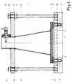
- FIG 1 1 is the horn antenna of a compact design Microwave level gauge shown.
- the Microwave level measuring device takes a position outside a metallic container, for example above a likewise metallic container lid 2.
- the explosive or aggressive or toxic measuring medium in the Interior 3 of the container is the explosive or aggressive or toxic measuring medium, the fill level with the Microwave level measuring device is to be measured. Since the metallic container wall reflects electromagnetic waves, the measurement is not directly through the container wall possible. That's why the level meter is so above one arranged circular cylindrical opening 4 that the electromagnetic Waves via the horn antenna 1 directly on the Surface of the measuring medium are directed.
- the opening 4 completely penetrates the container lid 2. With the circular cylindrical Opening 4 can be a for monitoring the inside of the container already exists, but also a new one that was brought in for this purpose Act opening.
- the opening 4 is the opening 4 with a disc 5 closed from a quartz glass or a ceramic material.
- the material of the quartz glass or ceramic is chosen so that it is one for the permeability of the Microwave favorable low dielectric constant and has the lowest possible loss factor. Also it is necessary to change the wall thickness of the quartz glass or the Choose ceramics so that a safe separation of the process and the environment is guaranteed.
- the diameter of the window has at least the antenna opening area of the horn antenna 1 to match. In the described embodiment have such windows from a 25 mm thick Borosilicate glass and openings with an opening diameter proven of 150 mm.
- quartz glass or ceramic disc 5 To attach the quartz glass or ceramic disc 5 to the Container lid 2 surrounds a surrounding ring 6 the quartz glass or ceramic disc 5.
- the fastening screws 7 form together with threaded holes 8 a releasable connection by means of which the mounting ring 6 positively connected to the container wall 2 is.
- the quartz glass or ceramic disk 5 or the mounting ring 6 by any other, the expert known type of attachment connected to the container lid 2 be.
- the microwave level measurement through such a glass window has so far failed because, despite the comparatively low dielectric constants of the glasses used, because of the thickness of the glass or ceramic required for the separation of process and environment, strong reflections on the top and bottom within the required bandwidth of the short-wave electromagnetic waves
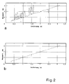
- FIG. 2a is the abscissa axis the measuring distance in meters and as the ordinate axis of the Measured value also plotted in meters.
- the curve poses that when measuring through the quartz glass or ceramic disc on the surface of one in a container Measurement signal received from the microwave fill level measuring device As can be seen from curve 2a, kick accumulated incorrect measurements. That of multiple reflections originating false echoes in the vicinity of the antenna of approx. 0.5 Meters to about 3.5 meters form such a high interference level, that a safe measurement of the level in this area not possible.
- the damping coefficient of the damping layer can be set for example from a commercially available damping mat consist of an ECCOSORB AN from GRACE N.V., Belgium.
- the interposition of a damping layer also brings the Advantage that the choice of damping factor
- the steepness of the interference signal i.e. the signal-to-noise ratio as a function of distance and thus the absolute height of the useful signal and the measuring range associated with it can be adjusted.
- the device of Figure 1 further shows an attachment for the level meter on the lid 2 of the container.
- an annular flange 10 runs coaxially with the same Distance the socket ring 6.
- the ring flange 10 has a series of threaded holes 11. These are along a bolt circle with the same distance in the ring flange 10 introduced.
- the ring flange 10 is by means of a Non-detachable welded connection to the container lid 2 connected.
- the mounting flange 12 runs in a form-fitting manner coaxial the upper edge of the horn antenna 1 and the outer surface of the waveguide tube 13.
- the excitation pin of the microwave coupling element 18 penetrates the outer surface of the waveguide tube 13 and protrudes a bit radially into the Interior of the waveguide tube 13.
- the microwave coupling element 18 is via a coaxial line with the electronic Transmitter and receiver part connected.
- the mounting flange 12 has a range of circumference Through holes 14, which are the same as the threaded holes 11 of the ring flange 10 on the mounting flange 12 are distributed.
- the threaded holes 11 and the through> gear bores 14 lie opposite one another. Between Flanges 10 and 12 threaded columns 15 are arranged. The Threaded columns 15 are supported in the threaded holes 11 of the ring flange 10. The mounting flange 12 is further between two nuts 16, 17 of the threaded columns 15 clamped.
- the level measuring device is thus detachable connected to the container lid 2. This type of attachment allows the distance of the level measuring device to the container lid 2 and thus the distance from the edge of the Horn antenna 1 to the glass or ceramic disc 5 through simply loosen, adjust and tighten again the mounting flange 12 and the nuts 16, 17 formed Adjust screw connection precisely. Such Adjustment is necessary because of the distance between the horn antenna 1 and the glass or ceramic pane 5 shows the signal-to-noise ratio in a spatial area kept particularly large near the window can be.
- Figures 3 and 4 show the effect of the invention based on the diagrams of the echo function.
- the diagram of Figure 3 is again the distance in meters as the axis of abscissa and the signal power in dB is plotted as the ordinate axis.
- the upper curve a shows the echo function without a damping layer 9 and curve b the echo function with damping layer 9 at a measuring distance of 1.2 m.
- the first large maximum represents the transmission pulse.
- the maximum at 0 m is the reflection on the surface the glass or ceramic disc 5.
- curve a is the reflection on the surface of the Disc 5 without damping layer 9 about 20 dB stronger more pronounced than in curve b with the interposition of the Damping layer 9.
- the diagram of Figure 4 shows the same echo function a measuring distance of 2.2 m.
- the useful signal can still be evaluated, but a lower one Has signal-to-noise ratio, such as that with interposition the damping layer 9 is the case.
- the interference signal becomes much smoother due to the damping.
Landscapes
- Physics & Mathematics (AREA)
- Electromagnetism (AREA)
- Thermal Sciences (AREA)
- Fluid Mechanics (AREA)
- General Physics & Mathematics (AREA)
- Measurement Of Levels Of Liquids Or Fluent Solid Materials (AREA)
Description
- Figur 1
- Einen Schnitt durch die Anordnung eines Mikrowellenfüllstandsmeßgerätes oberhalb eines Sichtglasfensters eines Behälters.
- Figur 2
- Die Diagramme a, b:
zeigend den Verlauf der Meßwerte des Mikrowellenfüllstandsmeßgerätes in Anwendung ohne und mit der Anordnung nach der Figur 1. - Figur 3
- Die Diagramme der Echofunktion der Mikrowellen bei einer Entfernung von 1,2 Meter wiederum in Anwendung ohne und mit der Anordnung nach der Figur 1.
- Figur 4
- Die Diagramme der Echofunktion der Mikrowellen bei einer Meßentfernung von 2,2 Meter in Anwendung ohne und mit der Anordnung nach der Figur 1.
Claims (11)
- Vorrichtung zur Füllstandsmessung in Behältern mit einem Füllstandsmeßgerät, durch welches mittels einer Hornantenne kurzwellige elektromagnetische Wellen durch eine Öffnung des Behälters auf die Oberfläche eines in dem Behälter befindlichen Füllguts gesendet, an der Oberfläche reflektiert und über die gleiche Hornantenne von dem Füllstandsmeßgerät empfangen werden, gekennzeichnet durch die folgenden Merkmale:a) Das Füllstandsmeßgerät ist einschließlich der Hornantenne (1) entlang einer Symmetrieachse der Öffnung (4) oder einer um wenige Grade von der Symmetrieachse abweichenden Achse außerhalb des Behälterinnenraumes (3) an der Behälterwand (2) angeordnet;b) Die Öffnung (4) ist von einer Glas- oder Keramikscheibe (5) verschlossen;c) Zwischen einem Mikrowellenkopplungselement (18) des Füllstandsmeßgerätes und der Oberfläche der Glas- oder Keramikscheibe (5) ist eine Bedämpfungsschicht (9) zwischengefügt;d) Die Bedämpfungsschicht (9) nimmt zwischen dem Mikrowellenkopplungselement (18) und der Glas- oder Keramikscheibe (5) eine solche Lage ein, daß jede abgestrahlte oder reflektierte, die Bedämpfungsschicht durchdringende elektromagnetische Welle eine Bedämpfung erfährt.
- Füllstandsmeßgerät nach Anspruch 1 dadurch gekennzeichnet, daß die Bedämpfungsschicht (9) durch einen Abschnitt einer handelsüblichen Bedämpfungsmatte gebildet ist.
- Vorrichtung nach Anspruch 2 dadurch gekennzeichnet, daß die Bedämpfungsschicht (9) aus einem ECCOSORB AN der Firma GRACE N.V., Belgien besteht.
- Vorrichtung nach Anspruch 1 dadurch gekennzeichnet, daß der, das Meßmedium enthaltene, Behälterinnenraum (3) durch die Glas- oder Keramikscheibe (5) gegenüber der Umwelt abgeschlossen ist.
- Vorrichtung nach Anspruch 4 dadurch gekennzeichnet, daß die Glas- oder Keramikscheibe (5) von Befestigungsmitteln (6) umgriffen ist.
- Vorrichtung nach Anspruch 5 dadurch gekennzeichnet, daß die Glas- oder Keramikscheibe (5) über die Befestigungsmittel (6) druckdicht und explosionsschützend mit der Behälterwand (2) verbunden ist.
- Vorrichtung nach Anspruch 4 dadurch gekennzeichnet, daß die Glas- oder Keramikscheibe (5) aus einem Werkstoff mit für die Durchlässigkeit von elektromagnetischen Wellen niedrigen dielektrischen Verlustfaktor und niedriger Dielektrizitätskonstante gebildet ist.
- Vorrichtung nach Anspruch 7 dadurch gekennzeichnet, daß die Glas- oder Keramikscheibe (5) aus einem Borosilikatglas gebildet ist.
- Vorrichtung nach Anspruch 1 dadurch gekennzeichnet, daß durch Wahl der räumlichen Distanz zwischen der Unterkante der Hornantenne (1) und der Oberfläche der Glas- oder Keramikscheibe (5) das Signal-Rauschverhältnis und die Signalstärke der elektromagnetischen Wellen einstellbar ist.
- Vorrichtung nach Anspruch 9 dadurch gekennzeichnet, daß Mittel (15, 16, 17) zur Veränderung und Festlegung der räumlichen Distanz zwischen der Unterkante der Hornantenne (1) und der Oberfläche der Glas- oder Keramikscheibe (5) vorhanden sind.
- Vorrichtung nach Anspruch 1 dadurch gekennzeichnet, daß durch Wahl des Dämpfungskoeffizienten das Signal-Rauschverhältnis und die Absoluthöhe des Nutzsignales einstellbar ist.
Applications Claiming Priority (3)
| Application Number | Priority Date | Filing Date | Title |
|---|---|---|---|
| DE4336494A DE4336494C2 (de) | 1993-10-26 | 1993-10-26 | Vorrichtung zur Füllstandsmessung in Behältern |
| DE4336494 | 1993-10-26 | ||
| PCT/DE1994/001229 WO1995012113A1 (de) | 1993-10-26 | 1994-10-17 | Vorrichtung zur füllstandsmessung in behältern |
Publications (2)
| Publication Number | Publication Date |
|---|---|
| EP0676037A1 EP0676037A1 (de) | 1995-10-11 |
| EP0676037B1 true EP0676037B1 (de) | 1998-05-20 |
Family
ID=6501048
Family Applications (1)
| Application Number | Title | Priority Date | Filing Date |
|---|---|---|---|
| EP94929482A Expired - Lifetime EP0676037B1 (de) | 1993-10-26 | 1994-10-17 | Vorrichtung zur füllstandsmessung in behältern |
Country Status (7)
| Country | Link |
|---|---|
| US (1) | US5594449A (de) |
| EP (1) | EP0676037B1 (de) |
| JP (1) | JP2664001B2 (de) |
| CA (1) | CA2152165C (de) |
| DE (2) | DE4336494C2 (de) |
| ES (1) | ES2116619T3 (de) |
| WO (1) | WO1995012113A1 (de) |
Cited By (1)
| Publication number | Priority date | Publication date | Assignee | Title |
|---|---|---|---|---|
| WO2024094353A1 (de) * | 2022-11-04 | 2024-05-10 | Endress+Hauser Flowtec Ag | Messanordnung |
Families Citing this family (46)
| Publication number | Priority date | Publication date | Assignee | Title |
|---|---|---|---|---|
| DE19532646A1 (de) * | 1995-09-05 | 1997-03-06 | Krohne Messtechnik Kg | Füllstandsmeßgerät |
| DE19542525C2 (de) * | 1995-11-15 | 1997-12-11 | Krohne Messtechnik Kg | Mikrowellenfenster |
| US5851083A (en) * | 1996-10-04 | 1998-12-22 | Rosemount Inc. | Microwave level gauge having an adapter with a thermal barrier |
| DE29709926U1 (de) * | 1997-06-08 | 1997-08-21 | Sailer, Josef, 87474 Buchenberg | System zum Erfassen von Füllständen |
| SE9702235L (sv) * | 1997-06-11 | 1998-06-22 | Saab Marine Electronics | Hornantenn |
| AU8404398A (en) | 1997-07-18 | 1999-02-10 | Kohler Company | Advanced touchless plumbing systems |
| ATE271214T1 (de) * | 1998-03-18 | 2004-07-15 | Grieshaber Vega Kg | Mikrowellen-füllstandsmessgerät geeignet zum betrieb bei hohen temperaturen und/oder hohen drücken und/oder chemisch aggressiver umgebung |
| US6166681A (en) * | 1998-08-18 | 2000-12-26 | Usx Corporation | Measuring the thickness of materials |
| US6325391B1 (en) * | 1998-11-12 | 2001-12-04 | Rosemount Inc. | PTFE window seal with EMI shielding |
| CA2251208A1 (en) | 1998-11-12 | 2000-05-12 | Claude Perreault | Fully automatic plating wax collecting device and method thereof |
| EP1070941A1 (de) * | 1999-07-23 | 2001-01-24 | Endress + Hauser GmbH + Co. | Vorrichtung zum Messen des Füllstandes in einem Behälter |
| US6310574B1 (en) * | 1999-08-05 | 2001-10-30 | Vega Grieshaber Kg | Level transmitter |
| DE10010713B4 (de) * | 2000-03-04 | 2008-08-28 | Endress + Hauser Gmbh + Co. Kg | Füllstandmeßgerät zum Aussenden und Empfangen breitbandiger hochfrequenter Signale |
| DE10028864A1 (de) * | 2000-06-10 | 2001-12-20 | Daimler Chrysler Ag | Verfahren und Vorrichtung zur Verbesserung der Temperaturstabilität und Alterungsbeständigkeit von Radar-Füllstandsmessern einer mechanischen Referenz |
| US7819003B2 (en) * | 2002-06-11 | 2010-10-26 | Intelligent Technologies International, Inc. | Remote monitoring of fluid storage tanks |
| DE10060069C1 (de) * | 2000-12-01 | 2002-04-25 | Krohne Messtechnik Kg | Mikrowellenfenster |
| DE10109453A1 (de) * | 2001-02-27 | 2002-09-26 | Endress & Hauser Gmbh & Co Kg | Vorrichtung zur Bestimmung und/oder Überwachung des Füllstands eines Füllguts in einem Behälter |
| US6853227B2 (en) | 2001-04-17 | 2005-02-08 | K-Tek Corporation | Controller for generating a periodic signal with an adjustable duty cycle |
| US6504409B1 (en) | 2001-04-17 | 2003-01-07 | K-Tek Corporation | Controller for generating a periodic signal with an adjustable duty cycle |
| US6658932B2 (en) | 2001-08-09 | 2003-12-09 | Anderson Instrument Co., Inc. | Measuring device and process seal therefor |
| US20080250869A1 (en) * | 2002-06-11 | 2008-10-16 | Intelligent Technologies International, Inc. | Remote Monitoring of Fluid Pipelines |
| US8994546B2 (en) * | 2002-06-11 | 2015-03-31 | Intelligent Technologies International, Inc. | Remote monitoring of material storage containers |
| DE20308619U1 (de) * | 2003-06-03 | 2004-10-14 | E.L.B. Explosionsschutzgeräte Bachmann GmbH & Co. | Sichtfenster-Anordnung in Gehäusen |
| EP1507133B1 (de) * | 2003-06-17 | 2016-06-29 | Endress + Hauser GmbH + Co. KG | Vorrichtung zur Überwachung eines Feldgeräts |
| US6988404B2 (en) * | 2003-12-11 | 2006-01-24 | Ohmart/Vega Corporation | Apparatus for use in measuring fluid levels |
| US7173436B2 (en) * | 2004-11-24 | 2007-02-06 | Saab Rosemount Tank Radar Ag | Antenna device for level gauging |
| DE102005056042B4 (de) | 2005-11-24 | 2015-11-05 | Vega Grieshaber Kg | Metallisierter Kunststoffantennentrichter für ein Füllstandradar |
| DE102005057094B4 (de) | 2005-11-30 | 2013-02-14 | Vega Grieshaber Kg | Füllstandradar mit variabler Sendeleistung |
| DE102007026389A1 (de) | 2007-06-06 | 2008-12-18 | Vega Grieshaber Kg | Antenne für ein Füllstandsradar für Hochtemperatur- und/oder Hochdruckanwendungen |
| US20090085794A1 (en) * | 2007-09-28 | 2009-04-02 | Rosemount Tank Radar Ab | Radar level gauge system |
| US9032565B2 (en) | 2009-12-16 | 2015-05-19 | Kohler Co. | Touchless faucet assembly and method of operation |
| US8350751B2 (en) * | 2010-03-10 | 2013-01-08 | Rosemount Tank Radar Ab | Radar level gauge with improved radar window |
| DE102012003948B4 (de) | 2012-03-01 | 2014-04-17 | Krohne Messtechnik Gmbh | Nach dem Radar-Prinzip arbeitendes Füllstandmesssystem |
| US8970424B2 (en) * | 2012-10-24 | 2015-03-03 | Rosemount Tank Radar Ab | Radar level gauge system with reduced antenna reflection |
| JP6323850B2 (ja) * | 2013-12-20 | 2018-05-16 | メイク株式会社 | 電波式レベル計および電波式レベル計の調整方法 |
| DE102014119260A1 (de) * | 2014-12-19 | 2016-06-23 | Endress + Hauser Flowtec Ag | Anschlußvorrichtung für ein Elektronik-Gehäuse sowie Meßwandler bzw. Feldgerät mit einer solchen Anschlußvorrichtung |
| ES2738328T3 (es) * | 2015-09-29 | 2020-01-22 | Handtmann Albert Maschf | Máquina llenadora y procedimiento para la medición de nivel de llenado con sensor de radar, en particular en la producción de salchichas |
| DE102015220578A1 (de) * | 2015-10-21 | 2017-04-27 | Vega Grieshaber Kg | Sondenendvorrichtung und Verfahren zum Herstellen einer Sondenendvorrichtung |
| JP6195966B1 (ja) * | 2016-10-26 | 2017-09-13 | メイク株式会社 | 電波式レベル計、及び電波式レベル計の取付方法 |
| US10725160B2 (en) * | 2017-04-07 | 2020-07-28 | Rosemount Tank Radar Ab | Non-invasive radar level gauge |
| JP6398027B1 (ja) * | 2018-02-13 | 2018-09-26 | メイク株式会社 | 電波式レベル計 |
| EP3569990B1 (de) * | 2018-05-17 | 2021-02-17 | VEGA Grieshaber KG | Befestigungsanordnung für ein radarfüllstandmessgerät |
| EP3693711B1 (de) * | 2019-02-11 | 2021-06-02 | VEGA Grieshaber KG | Radarmessvorrichtung mit plankonvexer linse |
| CN113566071A (zh) * | 2021-08-31 | 2021-10-29 | 南通世发船舶机械有限公司 | 一种船用液位计结构 |
| US12493355B2 (en) | 2022-04-14 | 2025-12-09 | Kohler Co. | Touchless plumbing control system |
| EP4266013A1 (de) * | 2022-04-20 | 2023-10-25 | Rosemount Tank Radar AB | Radarfüllstandsmesssystem mit einer antennenanordnung mit einem nichtplastischen dielektrischen antennenkörper |
Family Cites Families (7)
| Publication number | Priority date | Publication date | Assignee | Title |
|---|---|---|---|---|
| US4566321A (en) * | 1985-01-18 | 1986-01-28 | Transamerica Delaval Inc. | Microwave tank-contents level measuring assembly with lens-obturated wall-opening |
| US4670754A (en) * | 1985-12-30 | 1987-06-02 | Transamerica Delaval, Inc. | Microwave tank-contents level measuring assembly with a phase controlled lens |
| DE4100922A1 (de) * | 1991-01-15 | 1992-07-16 | Krohne Messtechnik Kg | Entfernungsmessgeraet, insbesondere zur fuellstandmessung von industrietanks |
| EP0524275A1 (de) * | 1991-02-12 | 1993-01-27 | Krohne Messtechnik Gmbh & Co. Kg | Elektrische schaltung für ein gerät zur füllstandmessung von industrietanks u. dgl. |
| US5115218A (en) * | 1991-03-11 | 1992-05-19 | Baker Hughes Inc. | Microwave process seal and method |
| SE504682C2 (sv) * | 1991-07-04 | 1997-04-07 | Saab Marine Electronics | Anordning för mätning av nivån av ett i en behållare befintligt medium |
| US5351036A (en) * | 1991-12-10 | 1994-09-27 | Clark-Reliance Corporation | Microwave-based point liquid level monitoring system |
-
1993
- 1993-10-26 DE DE4336494A patent/DE4336494C2/de not_active Expired - Fee Related
-
1994
- 1994-10-17 JP JP7512346A patent/JP2664001B2/ja not_active Expired - Lifetime
- 1994-10-17 US US08/464,614 patent/US5594449A/en not_active Expired - Lifetime
- 1994-10-17 DE DE59406027T patent/DE59406027D1/de not_active Expired - Fee Related
- 1994-10-17 CA CA002152165A patent/CA2152165C/en not_active Expired - Fee Related
- 1994-10-17 WO PCT/DE1994/001229 patent/WO1995012113A1/de not_active Ceased
- 1994-10-17 ES ES94929482T patent/ES2116619T3/es not_active Expired - Lifetime
- 1994-10-17 EP EP94929482A patent/EP0676037B1/de not_active Expired - Lifetime
Cited By (1)
| Publication number | Priority date | Publication date | Assignee | Title |
|---|---|---|---|---|
| WO2024094353A1 (de) * | 2022-11-04 | 2024-05-10 | Endress+Hauser Flowtec Ag | Messanordnung |
Also Published As
| Publication number | Publication date |
|---|---|
| DE4336494A1 (de) | 1995-04-27 |
| WO1995012113A1 (de) | 1995-05-04 |
| US5594449A (en) | 1997-01-14 |
| DE4336494C2 (de) | 1995-11-02 |
| JP2664001B2 (ja) | 1997-10-15 |
| DE59406027D1 (de) | 1998-06-25 |
| CA2152165A1 (en) | 1995-05-04 |
| EP0676037A1 (de) | 1995-10-11 |
| JPH08500907A (ja) | 1996-01-30 |
| ES2116619T3 (es) | 1998-07-16 |
| CA2152165C (en) | 1998-06-30 |
Similar Documents
| Publication | Publication Date | Title |
|---|---|---|
| EP0676037B1 (de) | Vorrichtung zur füllstandsmessung in behältern | |
| DE102012016120B4 (de) | Mikrowellenfenster und nach dem Radar-Prinzip arbeitendes Füllstandmesssystem | |
| EP0834722B1 (de) | Mit Mikrowellen arbeitendes Füllstandsmessgerät | |
| EP0668488B1 (de) | Anordnung zur Messung des Füllstands in einem Behälter | |
| EP2035790B1 (de) | Vorrichtung zur ermittlung und/oder überwachung des füllstandes eines mediums | |
| EP2331916B1 (de) | Mit mikrowellen arbeitendes füllstandsmessgerät | |
| EP0644999B1 (de) | Füllstandsmessgerät | |
| EP1285239B1 (de) | Füllstandsmessgerät | |
| EP0942264A2 (de) | Anordnung zur Füllstandsmessung | |
| WO2010136276A1 (de) | Anordnung zur füllstandsmessung mit einem mit mikrowellen arbeitenden füllstandsmessgerät | |
| CH675476A5 (de) | ||
| DE4419462C2 (de) | Berührungsloser Füllstandsmesser | |
| EP1325351A1 (de) | Vorrichtung zur bestimmung des füllstands eines füllguts in einem behälter | |
| DE4306193B4 (de) | Füllstandssensor | |
| EP1402234A2 (de) | Vorrichtung zur bestimmung und/oder überwachung des füllstands eines füllguts in einem behälter | |
| DE102005063079A1 (de) | Verfahren zur Ermittlung und Überwachung des Füllstands eines Mediums in einem Behälter | |
| EP1039273B1 (de) | Verfahren zur Füllstandsmessung | |
| EP1274973A2 (de) | Vorrichtung zur bestimmung des füllstandes eines füllguts in einem behälter | |
| EP3244176B1 (de) | Verfahren zur überwachung eines nach dem radarprinzip arbeitenden füllstandmessgerät und füllstandmessgerät | |
| EP0587834B1 (de) | Vorrichtung zur messung einer distanz mittels ultraschall | |
| DE3210591A1 (de) | Anordnung fuer eine kontinuierliche blasengehaltsmessung in hydraulikfluessigkeiten | |
| DE19820839A1 (de) | Füllstand-Meßvorrichtung | |
| DE102020124404A1 (de) | Integriertes Messgerät mit Füll- und/oder Grenzstandsensor und Druckmesszelle sowie Anordnung eines integrierten Messgerätes an einem Behälter | |
| DE1498291C (de) | Mehrstufige Ultraschallsonde zum Nachweis vorbestimmter Flussigkeits spiegel | |
| DE1498291B2 (de) | Mehrstufige ultraschallsonde zum nachweis vorbestimmter fluessigkeitsspiegel |
Legal Events
| Date | Code | Title | Description |
|---|---|---|---|
| PUAI | Public reference made under article 153(3) epc to a published international application that has entered the european phase |
Free format text: ORIGINAL CODE: 0009012 |
|
| 17P | Request for examination filed |
Effective date: 19950711 |
|
| AK | Designated contracting states |
Kind code of ref document: A1 Designated state(s): CH DE ES FR GB IT LI NL SE |
|
| GRAG | Despatch of communication of intention to grant |
Free format text: ORIGINAL CODE: EPIDOS AGRA |
|
| GRAG | Despatch of communication of intention to grant |
Free format text: ORIGINAL CODE: EPIDOS AGRA |
|
| GRAH | Despatch of communication of intention to grant a patent |
Free format text: ORIGINAL CODE: EPIDOS IGRA |
|
| 17Q | First examination report despatched |
Effective date: 19971111 |
|
| GRAH | Despatch of communication of intention to grant a patent |
Free format text: ORIGINAL CODE: EPIDOS IGRA |
|
| GRAA | (expected) grant |
Free format text: ORIGINAL CODE: 0009210 |
|
| AK | Designated contracting states |
Kind code of ref document: B1 Designated state(s): CH DE ES FR GB IT LI NL SE |
|
| REG | Reference to a national code |
Ref country code: CH Ref legal event code: EP |
|
| ITF | It: translation for a ep patent filed | ||
| REF | Corresponds to: |
Ref document number: 59406027 Country of ref document: DE Date of ref document: 19980625 |
|
| REG | Reference to a national code |
Ref country code: CH Ref legal event code: NV Representative=s name: ENDRESS + HAUSER FLOWTEC AG |
|
| REG | Reference to a national code |
Ref country code: ES Ref legal event code: FG2A Ref document number: 2116619 Country of ref document: ES Kind code of ref document: T3 |
|
| ET | Fr: translation filed | ||
| GBT | Gb: translation of ep patent filed (gb section 77(6)(a)/1977) |
Effective date: 19980817 |
|
| PLBE | No opposition filed within time limit |
Free format text: ORIGINAL CODE: 0009261 |
|
| STAA | Information on the status of an ep patent application or granted ep patent |
Free format text: STATUS: NO OPPOSITION FILED WITHIN TIME LIMIT |
|
| 26N | No opposition filed | ||
| PGFP | Annual fee paid to national office [announced via postgrant information from national office to epo] |
Ref country code: CH Payment date: 19990915 Year of fee payment: 6 |
|
| PGFP | Annual fee paid to national office [announced via postgrant information from national office to epo] |
Ref country code: SE Payment date: 19990920 Year of fee payment: 6 |
|
| PGFP | Annual fee paid to national office [announced via postgrant information from national office to epo] |
Ref country code: NL Payment date: 19990923 Year of fee payment: 6 |
|
| PGFP | Annual fee paid to national office [announced via postgrant information from national office to epo] |
Ref country code: ES Payment date: 19991020 Year of fee payment: 6 |
|
| PG25 | Lapsed in a contracting state [announced via postgrant information from national office to epo] |
Ref country code: ES Free format text: LAPSE BECAUSE OF NON-PAYMENT OF DUE FEES Effective date: 20001018 |
|
| PG25 | Lapsed in a contracting state [announced via postgrant information from national office to epo] |
Ref country code: SE Free format text: THE PATENT HAS BEEN ANNULLED BY A DECISION OF A NATIONAL AUTHORITY Effective date: 20001030 |
|
| PG25 | Lapsed in a contracting state [announced via postgrant information from national office to epo] |
Ref country code: LI Free format text: LAPSE BECAUSE OF NON-PAYMENT OF DUE FEES Effective date: 20001031 Ref country code: CH Free format text: LAPSE BECAUSE OF NON-PAYMENT OF DUE FEES Effective date: 20001031 |
|
| PG25 | Lapsed in a contracting state [announced via postgrant information from national office to epo] |
Ref country code: NL Free format text: LAPSE BECAUSE OF NON-PAYMENT OF DUE FEES Effective date: 20010501 |
|
| REG | Reference to a national code |
Ref country code: CH Ref legal event code: PL |
|
| EUG | Se: european patent has lapsed |
Ref document number: 94929482.1 |
|
| NLV4 | Nl: lapsed or anulled due to non-payment of the annual fee |
Effective date: 20010501 |
|
| REG | Reference to a national code |
Ref country code: GB Ref legal event code: IF02 |
|
| PGFP | Annual fee paid to national office [announced via postgrant information from national office to epo] |
Ref country code: GB Payment date: 20030929 Year of fee payment: 10 |
|
| PGFP | Annual fee paid to national office [announced via postgrant information from national office to epo] |
Ref country code: FR Payment date: 20031009 Year of fee payment: 10 |
|
| REG | Reference to a national code |
Ref country code: ES Ref legal event code: FD2A Effective date: 20011113 |
|
| PGFP | Annual fee paid to national office [announced via postgrant information from national office to epo] |
Ref country code: DE Payment date: 20041008 Year of fee payment: 11 |
|
| PG25 | Lapsed in a contracting state [announced via postgrant information from national office to epo] |
Ref country code: GB Free format text: LAPSE BECAUSE OF NON-PAYMENT OF DUE FEES Effective date: 20041017 |
|
| GBPC | Gb: european patent ceased through non-payment of renewal fee |
Effective date: 20041017 |
|
| PG25 | Lapsed in a contracting state [announced via postgrant information from national office to epo] |
Ref country code: FR Free format text: LAPSE BECAUSE OF NON-PAYMENT OF DUE FEES Effective date: 20050630 |
|
| REG | Reference to a national code |
Ref country code: FR Ref legal event code: ST |
|
| PG25 | Lapsed in a contracting state [announced via postgrant information from national office to epo] |
Ref country code: IT Free format text: LAPSE BECAUSE OF NON-PAYMENT OF DUE FEES;WARNING: LAPSES OF ITALIAN PATENTS WITH EFFECTIVE DATE BEFORE 2007 MAY HAVE OCCURRED AT ANY TIME BEFORE 2007. THE CORRECT EFFECTIVE DATE MAY BE DIFFERENT FROM THE ONE RECORDED. Effective date: 20051017 |
|
| PG25 | Lapsed in a contracting state [announced via postgrant information from national office to epo] |
Ref country code: DE Free format text: LAPSE BECAUSE OF NON-PAYMENT OF DUE FEES Effective date: 20060503 |