EP0676105B1 - Verfahren und anordnung zur dynamischen zuteilung mehrerer trägerwellenkanäle für mehrfachzugriff durch frequenzmultiplex - Google Patents
Verfahren und anordnung zur dynamischen zuteilung mehrerer trägerwellenkanäle für mehrfachzugriff durch frequenzmultiplex Download PDFInfo
- Publication number
- EP0676105B1 EP0676105B1 EP94900333A EP94900333A EP0676105B1 EP 0676105 B1 EP0676105 B1 EP 0676105B1 EP 94900333 A EP94900333 A EP 94900333A EP 94900333 A EP94900333 A EP 94900333A EP 0676105 B1 EP0676105 B1 EP 0676105B1
- Authority
- EP
- European Patent Office
- Prior art keywords
- frequency
- arrangement
- parallel
- conversion
- symbol
- Prior art date
- Legal status (The legal status is an assumption and is not a legal conclusion. Google has not performed a legal analysis and makes no representation as to the accuracy of the status listed.)
- Expired - Lifetime
Links
Images

Classifications
-
- H—ELECTRICITY
- H04—ELECTRIC COMMUNICATION TECHNIQUE
- H04J—MULTIPLEX COMMUNICATION
- H04J4/00—Combined time-division and frequency-division multiplex systems
-
- H—ELECTRICITY
- H04—ELECTRIC COMMUNICATION TECHNIQUE
- H04J—MULTIPLEX COMMUNICATION
- H04J1/00—Frequency-division multiplex systems
- H04J1/02—Details
- H04J1/08—Arrangements for combining channels
-
- H—ELECTRICITY
- H04—ELECTRIC COMMUNICATION TECHNIQUE
- H04J—MULTIPLEX COMMUNICATION
- H04J1/00—Frequency-division multiplex systems
- H04J1/02—Details
- H04J1/12—Arrangements for reducing cross-talk between channels
-
- H—ELECTRICITY
- H04—ELECTRIC COMMUNICATION TECHNIQUE
- H04L—TRANSMISSION OF DIGITAL INFORMATION, e.g. TELEGRAPHIC COMMUNICATION
- H04L7/00—Arrangements for synchronising receiver with transmitter
- H04L7/02—Speed or phase control by the received code signals, the signals containing no special synchronisation information
- H04L7/027—Speed or phase control by the received code signals, the signals containing no special synchronisation information extracting the synchronising or clock signal from the received signal spectrum, e.g. by using a resonant or bandpass circuit
Definitions
- the present invention relates to a method for dynamic allocation of multiple carrier-wave channels for multiple access by frequency division multiplexing and transmitter arrangements and receiver arrangements for carrying out the method.
- the invention is especially intended to be applied to mobile telecommunication systems.
- the invention provides a number of mobile units with the possibility for flexible data speed and continuous transmission. On the fixed side, the number of transmitters and receivers can be minimized by utilizing broadband receivers which serve several mobile units.
- the system is provided with a frequency band with fixed width at a certain frequency.
- Time division multiple access involves transmitting and receiving being divided into time gaps. Each channel has its predetermined time gap and the transmission speed can be varied by changing the length of the time gap.
- a disadvantage is that the system only uses one frequency at a time. TDMA is also sensitive to time dispersion due to the high channel data speed.
- Frequency division multiple access involves the frequency band being divided into frequency gaps with one transmitter/receiver in each narrow band with a carrier wave in the centre of the frequency gap. If it is attempted to increase the data speed by widening the carrier wave, interference is produced in adjacent frequency gaps, which is naturally a disadvantage. Moreover, it is uneconomical to have one transmitter for each frequency gap, which makes for a large number of transmitters.
- a bit stream has N serial data elements, which are converted to N parallel streams which modulate N subcarrier frequencies.
- the subcarriers are then frequency division multiplexed by Discrete or Fast Fourier Transform (DFT or FFT).
- DFT Discrete or Fast Fourier Transform
- the original bit stream is obtained in the reverse order using an inverse Fourier transform and a parallel to serial encoder.
- Data encoding and decoding, respectively, is performed before and after the serial to parallel converter and the parallel to serial converter, respectively.
- CDMA Code division multiple access
- the present invention is mostly related to FDMA in that a wider frequency band is divided into a number of subbands with a modulated carrier wave in each subband.
- a wider frequency band is divided into a number of subbands with a modulated carrier wave in each subband.
- a user will be able to allocate as many subbands as he needs for covering his data clock requirement. It should also be possible to vary this allocation of subbands with time.
- broadband transmitters/receivers are used which handle transmission over the entire accessible band.
- the present invention provides a method for dynamic allocation of multiple carrier-wave channels where the bit stream or bits streams which will be transmitted are subjected to conversion from serial form to parallel form with a number of outputs, each parallel output is allocated a frequency gap with a defined subcarrier wave, each subcarrier wave is subjected to symbol coding by being modulated by the respective parallel bit stream in order to provide a number of parallel symbols or parallel subcarrier waves.
- the parallel symbols are converted by inverse discrete Fourier transform to a sequence in the time domain, which sequence is D/A-converted to provide a baseband signal.
- the baseband signal is RF-modulated with a frequency at the centre of the overall accessible frequency band.
- the RF signal is demodulated to the baseband, the baseband signal is A/D-converted and the sample is frequency-demultiplexed by discrete Fourier transform which recreates the signal in frequency gaps. Suitable frequency gaps are selected taking into account the respective user and the signals in these frequency gaps are symbol-decoded into parallel bit streams which are converted to serial form for recreating the original bit stream.
- Frequency demultiplexing is advantageously carried out with oversampling in order to permit the best sampling time to be selected for the different frequency gaps.
- the invention also relates to transmitter and receiver arrangements for carrying out the method.
- the invention is specified in greater detail in the subsequent patent claims.
- Figure 1 shows the situation in, for example, a base station in a mobile telephone system.
- the base station is provided with a frequency band of, for example, 50 MHz.
- a number of users k will be served within the frequency band.
- the different users have different data clock requirements, partly between themselves and partly because their requirement varies with time.
- the total frequency band is divided into a number m, for example 50, of frequency bands with a subcarrier wave in each frequency gap.
- Each user is allocated a suitable number of frequency bands.
- a number of known methods for dividing the frequency band are today available, which are used inter alia for allocating time gaps in a TDMA system.
- the different subcarrier waves are not transmitted by separate transmitters in this case but by a single broadband transmitter, as is explained below with reference to Figures 2 and 3.
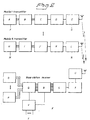
- FIG. 2 shows the uplink situation, that is to say the mobiles transmit to the base station.
- Each mobile which wishes to transmit has a message in the form of a bit stream.
- Each frequency gap has a fixed width of, for example, 1 MHz and thereby a limited data transmission speed.
- Allocation algorithms determine if the bit stream has space in one gap or how many gaps will be used. In general, a number of gaps or subbands are required.
- the bit stream is therefore first subjected to serial to parallel conversion so that each band is given a suitable data speed. This can be carried out in a known manner, for example by means of a shift register.
- the carrier waves in the subbands are then quadrature modulated with respective parallel bit streams, that is to say the subcarrier waves are subjected to symbol coding.
- Any suitable known modulation method can be used, for example BPSK, QPSK, QAM.
- the method has n bits/symbol and the modulation clocks 1 symbol/second (baud) which implies that the gross bit clock in each subband is n * 1 bits/second.
- This provides a number of parallel symbols or wave forms, that is to say parallel modulated subcarrier waves. These parallel symbols are found in the frequency domain. In gaps which will not be used a zero is applied.
- the sequence is then subjected to D/A conversion. This provides a single time-continuous analog baseband signal which fills up the complete allocated frequency band.
- the baseband signal can then be RF-modulated in a conventional manner at the centre frequency of the overall band, for example 900 MHz.
- the carrier wave frequency and output power can be adjusted at an RF modulator of the mobile in order to compensate for frequency error and to provide for power control for reasons which will be specified below.
- the received radio signal is converted to base band in the conventional manner by means of an RF demodulator.
- the baseband signal is A/D-converted.
- frequency demultiplexing is carried out by discrete Fourier transform (DFT) with m points.
- DFT discrete Fourier transform
- the choice of the "window" for this DFT determines the sampling times for the symbols in the subcarrier waves. This must be selected in such a manner that a maximum eye opening is obtained at the sampling time. Since the different mobiles are not synchronized to one another or at least only roughly synchronized, they will have different optimum sampling times.
- By carrying out frequency demultiplexing with oversampling different sampling times can be selected independently of one another for the different mobiles.
- Oversampling is obtained by the DFT being taken via a multiple overlapping window. Oversampling can be, for example, 2, 4 or 8 times. The more accurately the mobiles can be synchronized, the lower the oversampling required. Higher oversampling makes higher demands on a fast Fourier transform.
- the sequence obtained is sampled down, which involves the best sample (the window) being selected for a respective frequency gap. This is produced by feedback from the symbol decoding following. Higher layers report which frequencies belong to which user.
- the symbol decoding is done in parallel for the different gaps. Since receivers and transmitters are not synchronized, the right sampling time must be selected, hence the oversampling. The best point is selected as mentioned above
- the frequency error of the mobiles must also be kept within certain limits. Moreover, their output power must be adjusted so that all mobiles set the transmitted power level in such a manner that the received levels at the base stations become essentially identical. In the symbol decoding, errors in frequency and power are therefore measured which are fed back to the respective mobiles by the associated control logic. A number of known methods are available for this. Furthermore, errors in the sampling time are fed back to the unit which selects which sample will be used for the respective mobile.
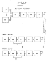
- Figure 3 shows the downlink configuration.
- the transmitter in the base station is mainly the same as the transmitters in the mobile stations.
- the base station serves a number of users.
- serial-to-parallel conversion is carried out for each user.
- Higher layers handle the allocation of frequency gaps.
- the transmitter has a stable carrier wave frequency. There is a possibility of transmitting at different power in different frequency bands in order to adapt the power to the different receivers which are generally located at different distances from the base station.
- the receivers in the mobile stations are simplified compared with the receivers in the base station. Since each mobile generally only receives signals from one base station, there is no problem with different synchronizations in the received signal. It is therefore not necessary to carry out oversampling in frequency demultiplexing in the mobile. Instead, the sampling time is selected on the basis of a feedback from the subsequent symbol decoder. The window can thereby be set to a suitable time which, of course, is the same for all frequency bands since they are transmitted from the same transmitter, namely the base station, and received at the one place in the mobile.
- Asymmetric data traffic is thus possible, for example, with 10 kbit in one direction and 50 kbit in the other.
- the higher layer has access to a logic channel for signalling.
- information about allocation of channels, type of transmission, synchronization etc. is exchanged, as is known in the field.
- the present invention provides a novel system for the allocation of multiple carrier wave channels by frequency division multiplexing which utilizes Fourier transform and oversampling.
- An advantage of placing high data clocks in a number of parallel frequency bands is that the symbol clock becomes lower and with it the sensitivity to time dispersion.
- the protective scope of the invention is limited only by the patent claims following.
Landscapes
- Engineering & Computer Science (AREA)
- Computer Networks & Wireless Communication (AREA)
- Signal Processing (AREA)
- Mobile Radio Communication Systems (AREA)
- Time-Division Multiplex Systems (AREA)
- Digital Transmission Methods That Use Modulated Carrier Waves (AREA)
Claims (8)
- Verfahren zur dynamischen Zuordnung von mehreren Trägerwellenkanälen,
mit den folgenden senderseitigen Schritten:und mit den folgenden empfängerseitigen Schritten:daß mindestens ein Bitstrom einer Umwandlung (A, H, AA, BB) unterworfen wird von der seriellen Form in die parallele Form mit einer Anzahl von Ausgängen;daß jedem parallelen Ausgang eine Frequenzlücke mit einer definierten Hilfsträgerwelle zugeordnet wird;daß jede Hilfsträgerwelle einer Symbolcodierung (B, I, CC) unterworfen wird, indem sie mit dem jeweiligen parallelen Bitstrom moduliert wird, wobei eine Anzahl von parallelen Symbolen erhalten wird;daß die parallelen Symbole durch eine inverse diskrete Fouriertransformation (C, J, DD) in eine Sequenz in der Zeitdomäne umgewandelt werden;daß die Sequenz D/A-gewandelt wird (D, K, EE), was ein im wesentlichen zeitkontinuierliches Basisbandsignal ergibt;daß das Basisbandsignal HF-moduliert (E, L, FF) wird mit einer Frequenz im Zentrum des insgesamt zugänglichen Frequenzbandes;daß das HF-Signal in das Basisband moduliert (U, KK, QQ) wird;daß das Basisbandsignal A/D-gewandelt (T, JJ, PP) wird;daß der Abtastwert frequenz-demultiplext wird (S, II, OO) durch diskrete Fouriertransformation, was eine Aufteilung des Signals in Frequenzlücken ergibt;daß geeignete Frequenzlücken gewählt werden;daß die Signale in diesen Frequenzlücken in eine Anzahl von parallelen Bitströmen symbol-decodiert (Q, HH, NN) werden unddaß diese parallelen Bitströme in mindestens einen seriellen Bitstrom konvertiert (O, P, GG, MM) werden in Entsprechung mit einem ursprünglichen Bitstrom. - Verfahren nach Anspruch 1, dadurch gekennzeichnet, daß die Symboldecodierung eine Rückkopplung (F, M, LL) liefert zum Einstellen der Abtastzeit beim Frequenz-Demultiplexen.
- Verfahren nach Anspruch 2, dadurch gekennzeichnet, daß der Empfänger Signale von einer Anzahl von Sendern empfängt, mit den weiteren Schritten:daß beim Frequenz-Demultiplexen ein Oversampling ausgeführt wird;daß die beste Abtastzeit für die jeweilige Frequenzlücke mit Hilfe der Rückkopplung (F, M, LL) von der Symboldecodierung gewählt wird.
- Verfahren nach einem der vorangehenden Ansprüche, dadurch gekennzeichnet, daß Information von der Symboldecodierung zu der HF-Modulation rückgekoppelt wird (G, N) zum Einstellen der Trägerwellenfrequenz und Ausgangsleistung.
- Sendeanordnung mit dynamischer Zuordnung von mehreren Trägerwellenkanälen, mit:einer Anordnung für die Seriell-Zu-Parallel-Umwandlung (A, H, AA, BB) mindestens eines Bitstroms für eine Anzahl von Ausgängen;einer Anordnung zum Symbolcodieren (B, I, CC) von Hilfsträgerwellen mit jeweiligen parallelen Bitströmen;einer Anordnung zum Frequenz-Teilungs-Multiplexen (C, J, DD) der Hilfsträgerwellen durch inverse diskrete Fouriertransformation in eine Sequenz in der Zeitdomäne;einer Anordnung zur D/A-Umwandlung (D, K, EE) der Sequenz in ein im wesentlichen zeitkontinuierliches Basisbandsignal; undeiner Modulationsanordnung zur HF-Modulation (E, L, FF) des Basisbandsignals.
- Empfängeranordnung zur dynamischen Zuordnung von mehreren Trägerwellenkanälen, mit:einer Modulationsanordnung (U, KK, QQ) zum Demodulieren eines HF-Signals zu dem Basisband;einer Anordnung zur A/D-Umwandlung (T, JJ, PP) des Basisbandsignals in ein digitales Signal;einer Anordnung zum Frequenz-Demultiplexen (S, II, OO) des digitalen Signals durch diskrete Fouriertransformation derart, daß es über Frequenzlücken verteilt wird;einer Anordnung zum Symbol-Decodieren (Q, HH, NN) der Signale in jeder Frequenzlücke zu parallelen Bitströmen;einer Anordnung zur Parallel-Zu-Seriell-Konversion (O, P, GG, MM) von ausgewählten Bitströmen.
- Empfängeranordnung nach Anspruch 6, dadurch gekennzeichnet, daß die SymboldecodierungsAnordnung zu der Frequenz-Demultiplex-Anordnung rückgekoppelt ist (LL, RR) zum Einstellen der Abtastzeiten.
- Empfängeranordnung nach Anspruch 6 oder 7, dadurch gekennzeichnet, daß die Frequenzdemultiplex-Anordnung ein Oversampling durchführt und daß die Empfängeranordnung ferner eine Step-Down-Sampling-Anordnung (R) umfaßt, zu der die Symboldecodierungsanordnung rückgekoppelt ist (X), so daß die Step-Down-Sampling-Anordnung die beste Abtastzeit für die jeweilige Frequenzlücke auswählen kann.
Applications Claiming Priority (3)
| Application Number | Priority Date | Filing Date | Title |
|---|---|---|---|
| SE9203384A SE9203384L (sv) | 1992-11-13 | 1992-11-13 | Förfarande och anordning för dynamisk allokering av multipla bärvågskanaler för multipelaccess genom frekvensmultiplexering |
| SE9203384 | 1992-11-13 | ||
| PCT/SE1993/000941 WO1994011961A1 (en) | 1992-11-13 | 1993-11-09 | Method and arrangement for dynamic allocation of multiple carrier-wave channels for multiple access by frequency division multiplexing |
Publications (2)
| Publication Number | Publication Date |
|---|---|
| EP0676105A1 EP0676105A1 (de) | 1995-10-11 |
| EP0676105B1 true EP0676105B1 (de) | 2001-10-17 |
Family
ID=20387788
Family Applications (1)
| Application Number | Title | Priority Date | Filing Date |
|---|---|---|---|
| EP94900333A Expired - Lifetime EP0676105B1 (de) | 1992-11-13 | 1993-11-09 | Verfahren und anordnung zur dynamischen zuteilung mehrerer trägerwellenkanäle für mehrfachzugriff durch frequenzmultiplex |
Country Status (5)
| Country | Link |
|---|---|
| US (1) | US5680388A (de) |
| EP (1) | EP0676105B1 (de) |
| DE (1) | DE69330964T2 (de) |
| SE (1) | SE9203384L (de) |
| WO (1) | WO1994011961A1 (de) |
Families Citing this family (39)
| Publication number | Priority date | Publication date | Assignee | Title |
|---|---|---|---|---|
| EP0687084A3 (de) * | 1994-06-06 | 1997-10-22 | Prueftechnik Und Mobile Kommun | Kommunikationsvorrichtung mit variabler Bandbreite |
| US6334219B1 (en) | 1994-09-26 | 2001-12-25 | Adc Telecommunications Inc. | Channel selection for a hybrid fiber coax network |
| GB2296165B (en) * | 1994-12-15 | 1999-12-29 | Int Mobile Satellite Org | Multiplex communication |
| US5754597A (en) * | 1994-12-29 | 1998-05-19 | Motorola, Inc. | Method and apparatus for routing a digitized RF signal to a plurality of paths |
| US5579341A (en) * | 1994-12-29 | 1996-11-26 | Motorola, Inc. | Multi-channel digital transceiver and method |
| US7280564B1 (en) | 1995-02-06 | 2007-10-09 | Adc Telecommunications, Inc. | Synchronization techniques in multipoint-to-point communication using orthgonal frequency division multiplexing |
| USRE42236E1 (en) | 1995-02-06 | 2011-03-22 | Adc Telecommunications, Inc. | Multiuse subcarriers in multipoint-to-point communication using orthogonal frequency division multiplexing |
| GB9510619D0 (en) * | 1995-05-25 | 1995-07-19 | Philips Electronics Uk Ltd | Telecommunications system |
| FI116651B (fi) * | 1995-07-03 | 2006-01-13 | Nokia Mobile Phones Ltd | Kapeakaistaiseen TDMA-järjestelmään perustuva laajakaistainen sovellus |
| KR100648475B1 (ko) * | 1996-01-29 | 2007-01-31 | 소니 가부시끼 가이샤 | 통신자원할당방법및장치 |
| JP3780551B2 (ja) * | 1996-01-29 | 2006-05-31 | ソニー株式会社 | 多元接続による信号送信方法及び装置 |
| US5790549A (en) * | 1996-02-29 | 1998-08-04 | Ericsson Inc. | Subtractive multicarrier CDMA access methods and systems |
| JPH09321721A (ja) * | 1996-05-27 | 1997-12-12 | Sony Corp | 送信方法,送信装置,受信方法及び受信装置 |
| FR2753024B1 (fr) * | 1996-08-27 | 1998-12-31 | France Telecom | Dispositif et procede de reception d'un signal amrf constitue de frequences porteuses emises par au moins deux terminaux, et systeme de transmission correspondant |
| JP3718927B2 (ja) * | 1996-11-08 | 2005-11-24 | ソニー株式会社 | 通信方法及び端末装置 |
| EP0854619A1 (de) * | 1997-01-15 | 1998-07-22 | Alcatel | Datenbitverteilungsverfahren, Mehrträgersender und -empfänger zur Durchführung des Verfahrens, und entsprechender Verteilungsmeldungsgenerator |
| US6175550B1 (en) * | 1997-04-01 | 2001-01-16 | Lucent Technologies, Inc. | Orthogonal frequency division multiplexing system with dynamically scalable operating parameters and method thereof |
| US6005840A (en) * | 1997-04-01 | 1999-12-21 | Lucent Technologies Inc. | Complementary encoding and modulation system for use in an orthogonal frequency division multiplexing transmitter system and method thereof |
| US6097712A (en) * | 1997-06-20 | 2000-08-01 | Nortel Networks Limited | Multi-carrier CDMA communications systems |
| US6810030B1 (en) * | 1997-10-17 | 2004-10-26 | Lucent Technology | Dynamic and smart spreading for wideband CDMA |
| EP0932284A3 (de) * | 1998-01-27 | 2002-08-14 | Hitachi Denshi Kabushiki Kaisha | Mehrträgerübertragungssystem mit veränderbarer Bandbreite |
| JP3515690B2 (ja) * | 1998-06-02 | 2004-04-05 | 松下電器産業株式会社 | Ofdma信号伝送装置及び方法 |
| US6542485B1 (en) | 1998-11-25 | 2003-04-01 | Lucent Technologies Inc. | Methods and apparatus for wireless communication using time division duplex time-slotted CDMA |
| US6813254B1 (en) | 1998-11-25 | 2004-11-02 | Lucent Technologies Inc. | Methods and apparatus for wireless communication using code division duplex time-slotted CDMA |
| US7020071B2 (en) | 1998-11-25 | 2006-03-28 | Lucent Technologies Inc. | Methods and apparatus for wireless communication using orthogonal frequency division multiplexing |
| EP1277317A2 (de) * | 2000-04-22 | 2003-01-22 | Atheros Communications, Inc. | Mehrträgerkommunikationssystem unter verwendung von veränderlichen ofdm-symbolraten und veränderlicher anzahl der träger |
| US6975585B1 (en) | 2000-07-27 | 2005-12-13 | Conexant Systems, Inc. | Slotted synchronous frequency division multiplexing for multi-drop networks |
| GB0020624D0 (en) * | 2000-08-21 | 2000-10-11 | Element 14 Inc | Multi band DMT receiver |
| US6763025B2 (en) | 2001-03-12 | 2004-07-13 | Advent Networks, Inc. | Time division multiplexing over broadband modulation method and apparatus |
| US6891841B2 (en) * | 2001-03-12 | 2005-05-10 | Advent Networks, Inc. | Time division multiple access over broadband modulation method and apparatus |
| EP1478148A1 (de) | 2003-05-15 | 2004-11-17 | Siemens Aktiengesellschaft | Drahtloses Mehrträgerkommunikationsverfahren mit dynamischer Aufteilung der Frequenzbreite und Anzahl der Subbänder |
| US7869528B2 (en) * | 2003-10-31 | 2011-01-11 | Northrop Grumman Systems Corporation | Multi-carrier transceiver assembly |
| JP4441429B2 (ja) * | 2005-03-30 | 2010-03-31 | 京セラ株式会社 | 無線送信装置 |
| CN100571238C (zh) * | 2005-08-29 | 2009-12-16 | 中国科学院上海微系统与信息技术研究所 | 多载波系统的发射、接收装置及其发射、接收方法 |
| US7561542B2 (en) * | 2006-05-12 | 2009-07-14 | Meshnetworks, Inc. | System, method and apparatus for determining if data from a source has arrived properly at a destination in a time division multiplex (TDM) communication network |
| US7813373B2 (en) * | 2006-05-25 | 2010-10-12 | Motorola, Inc. | Systems, methods and apparatus for detecting time slot interference and recovering from time slot interference in an ad hoc wireless communication network |
| US7929546B2 (en) * | 2006-05-25 | 2011-04-19 | Motorola Solutions, Inc. | Systems, methods and apparatus for allocating time slots in an ad hoc wireless communication network |
| CN105391669B (zh) * | 2014-09-09 | 2018-04-24 | 国家电网公司 | 一种电力线通信频谱碎片整理方法和装置 |
| EP4024727A1 (de) | 2017-11-02 | 2022-07-06 | Intelsat US LLC | Verfahren und systeme zur erhöhung der bandbreiteneffizienz in der satellitenkommunikation |
Family Cites Families (4)
| Publication number | Priority date | Publication date | Assignee | Title |
|---|---|---|---|---|
| US4827336A (en) * | 1987-12-18 | 1989-05-02 | General Electric Company | Symbol code generation processing from interframe DPCM of TDM'd spatial-frequency analyses of video signals |
| US5187711A (en) * | 1988-09-20 | 1993-02-16 | Fujitsu Limited | Error correction method for multicarrier radio transmission system |
| US5115309A (en) * | 1990-09-10 | 1992-05-19 | At&T Bell Laboratories | Method and apparatus for dynamic channel bandwidth allocation among multiple parallel video coders |
| US5274627A (en) * | 1991-07-10 | 1993-12-28 | International Telecommunications Satellite Organization | Non-regenerative multibeam satellite communications system with FDMA access and SSTDM connectivity |
-
1992
- 1992-11-13 SE SE9203384A patent/SE9203384L/ not_active Application Discontinuation
-
1993
- 1993-11-09 WO PCT/SE1993/000941 patent/WO1994011961A1/en not_active Ceased
- 1993-11-09 EP EP94900333A patent/EP0676105B1/de not_active Expired - Lifetime
- 1993-11-09 US US08/424,480 patent/US5680388A/en not_active Expired - Lifetime
- 1993-11-09 DE DE69330964T patent/DE69330964T2/de not_active Expired - Fee Related
Also Published As
| Publication number | Publication date |
|---|---|
| US5680388A (en) | 1997-10-21 |
| SE9203384D0 (sv) | 1992-11-13 |
| EP0676105A1 (de) | 1995-10-11 |
| SE470038B (sv) | 1993-10-25 |
| DE69330964D1 (de) | 2001-11-22 |
| DE69330964T2 (de) | 2002-06-20 |
| SE9203384L (sv) | 1993-10-25 |
| WO1994011961A1 (en) | 1994-05-26 |
Similar Documents
| Publication | Publication Date | Title |
|---|---|---|
| EP0676105B1 (de) | Verfahren und anordnung zur dynamischen zuteilung mehrerer trägerwellenkanäle für mehrfachzugriff durch frequenzmultiplex | |
| US5828650A (en) | Combined modulation--and multiple access method for radio signals | |
| AU710869B2 (en) | Communication resourse allocation method and apparatus | |
| US6430148B1 (en) | Multidirectional communication systems | |
| EP2388938B1 (de) | Funkübertragungsvorrichtung, Funkempfangsvorrichtung und Verfahren dafür | |
| KR100437306B1 (ko) | 직교주파수분할 다중 변복조 회로 | |
| US7787514B2 (en) | Carrier interferometry coding with applications to cellular and local area networks | |
| US6385190B1 (en) | Mobile communications system which uses TDMA for speech data and OFDM for control/extended data | |
| CA2317973C (en) | Method and apparatus for identifying an orthogonal frequency division multiplexing (ofdm) terrestrial repeater using inactive sub-carriers | |
| GB2118401A (en) | Improvements in or relating to communication systems and to transmitters and recievers therefor | |
| JPS6335025A (ja) | デジタル無線伝送系 | |
| JP2000509214A (ja) | ポイント―ツーマルチポイント無線伝送系 | |
| US6542460B1 (en) | Relating to multidirectional communication systems | |
| JPH09266466A (ja) | デジタル伝送システム | |
| US7573807B1 (en) | Method and apparatus for performing differential modulation over frequency in an orthogonal frequency division multiplexing (OFDM) communication system | |
| KR20000068608A (ko) | 무선 통신 시스템 | |
| US7974255B2 (en) | Method and apparatus for multi-stream transmission with time and frequency diversity in an orthogonal frequency division multiplexing (OFDM) communication system | |
| KR20000048446A (ko) | 캐리어 오프셋 상에 기반을 둔 트랜시버 프리 로테이션 | |
| US5533030A (en) | Radiotelephone system with the character of a local or auxiliary communications apparatus | |
| KR100648475B1 (ko) | 통신자원할당방법및장치 | |
| GB2373148A (en) | Intra symbol differential modulation of a multi-carrier signal | |
| KR20060085130A (ko) | 직교 주파수 분할 다중 접속 시스템에서의 다중 송신기 |
Legal Events
| Date | Code | Title | Description |
|---|---|---|---|
| PUAI | Public reference made under article 153(3) epc to a published international application that has entered the european phase |
Free format text: ORIGINAL CODE: 0009012 |
|
| 17P | Request for examination filed |
Effective date: 19950505 |
|
| AK | Designated contracting states |
Kind code of ref document: A1 Designated state(s): CH DE ES FR GB IT LI NL |
|
| 17Q | First examination report despatched |
Effective date: 20000113 |
|
| GRAG | Despatch of communication of intention to grant |
Free format text: ORIGINAL CODE: EPIDOS AGRA |
|
| RTI1 | Title (correction) |
Free format text: METHOD AND ARRANGEMENT FOR DYNAMIC ALLOCATION OF MULTIPLE CARRIER-WAVE CHANNELS FOR MULTIPLE ACCESS BY FREQUENCY DIVISION MULTIPLEXING |
|
| RIN1 | Information on inventor provided before grant (corrected) |
Inventor name: KAHRE, RAGNAR |
|
| GRAG | Despatch of communication of intention to grant |
Free format text: ORIGINAL CODE: EPIDOS AGRA |
|
| GRAH | Despatch of communication of intention to grant a patent |
Free format text: ORIGINAL CODE: EPIDOS IGRA |
|
| GRAH | Despatch of communication of intention to grant a patent |
Free format text: ORIGINAL CODE: EPIDOS IGRA |
|
| GRAA | (expected) grant |
Free format text: ORIGINAL CODE: 0009210 |
|
| AK | Designated contracting states |
Kind code of ref document: B1 Designated state(s): CH DE ES FR GB IT LI NL |
|
| PG25 | Lapsed in a contracting state [announced via postgrant information from national office to epo] |
Ref country code: NL Free format text: LAPSE BECAUSE OF FAILURE TO SUBMIT A TRANSLATION OF THE DESCRIPTION OR TO PAY THE FEE WITHIN THE PRESCRIBED TIME-LIMIT Effective date: 20011017 Ref country code: LI Free format text: LAPSE BECAUSE OF FAILURE TO SUBMIT A TRANSLATION OF THE DESCRIPTION OR TO PAY THE FEE WITHIN THE PRESCRIBED TIME-LIMIT Effective date: 20011017 Ref country code: IT Free format text: LAPSE BECAUSE OF FAILURE TO SUBMIT A TRANSLATION OF THE DESCRIPTION OR TO PAY THE FEE WITHIN THE PRE;WARNING: LAPSES OF ITALIAN PATENTS WITH EFFECTIVE DATE BEFORE 2007 MAY HAVE OCCURRED AT ANY TIME BEFORE 2007. THE CORRECT EFFECTIVE DATE MAY BE DIFFERENT FROM THE ONE RECORDED.SCRIBED TIME-LIMIT Effective date: 20011017 Ref country code: CH Free format text: LAPSE BECAUSE OF FAILURE TO SUBMIT A TRANSLATION OF THE DESCRIPTION OR TO PAY THE FEE WITHIN THE PRESCRIBED TIME-LIMIT Effective date: 20011017 |
|
| REG | Reference to a national code |
Ref country code: CH Ref legal event code: EP |
|
| PGFP | Annual fee paid to national office [announced via postgrant information from national office to epo] |
Ref country code: FR Payment date: 20011115 Year of fee payment: 9 |
|
| REF | Corresponds to: |
Ref document number: 69330964 Country of ref document: DE Date of ref document: 20011122 |
|
| REG | Reference to a national code |
Ref country code: GB Ref legal event code: IF02 |
|
| PGFP | Annual fee paid to national office [announced via postgrant information from national office to epo] |
Ref country code: DE Payment date: 20020130 Year of fee payment: 9 |
|
| ET | Fr: translation filed | ||
| NLV1 | Nl: lapsed or annulled due to failure to fulfill the requirements of art. 29p and 29m of the patents act | ||
| PG25 | Lapsed in a contracting state [announced via postgrant information from national office to epo] |
Ref country code: ES Free format text: LAPSE BECAUSE OF FAILURE TO SUBMIT A TRANSLATION OF THE DESCRIPTION OR TO PAY THE FEE WITHIN THE PRESCRIBED TIME-LIMIT Effective date: 20020430 |
|
| REG | Reference to a national code |
Ref country code: CH Ref legal event code: PL |
|
| PLBE | No opposition filed within time limit |
Free format text: ORIGINAL CODE: 0009261 |
|
| STAA | Information on the status of an ep patent application or granted ep patent |
Free format text: STATUS: NO OPPOSITION FILED WITHIN TIME LIMIT |
|
| 26N | No opposition filed | ||
| PG25 | Lapsed in a contracting state [announced via postgrant information from national office to epo] |
Ref country code: DE Free format text: LAPSE BECAUSE OF NON-PAYMENT OF DUE FEES Effective date: 20030603 |
|
| PG25 | Lapsed in a contracting state [announced via postgrant information from national office to epo] |
Ref country code: FR Free format text: LAPSE BECAUSE OF NON-PAYMENT OF DUE FEES Effective date: 20030731 |
|
| REG | Reference to a national code |
Ref country code: FR Ref legal event code: ST |
|
| PGFP | Annual fee paid to national office [announced via postgrant information from national office to epo] |
Ref country code: GB Payment date: 20040809 Year of fee payment: 12 |
|
| PG25 | Lapsed in a contracting state [announced via postgrant information from national office to epo] |
Ref country code: GB Free format text: LAPSE BECAUSE OF NON-PAYMENT OF DUE FEES Effective date: 20051109 |
|
| GBPC | Gb: european patent ceased through non-payment of renewal fee |
Effective date: 20051109 |