EP0676167A1 - Federbefestigungsclip - Google Patents
Federbefestigungsclip Download PDFInfo
- Publication number
- EP0676167A1 EP0676167A1 EP95302364A EP95302364A EP0676167A1 EP 0676167 A1 EP0676167 A1 EP 0676167A1 EP 95302364 A EP95302364 A EP 95302364A EP 95302364 A EP95302364 A EP 95302364A EP 0676167 A1 EP0676167 A1 EP 0676167A1
- Authority
- EP
- European Patent Office
- Prior art keywords
- spring clip
- arms
- tool
- leash
- central portion
- Prior art date
- Legal status (The legal status is an assumption and is not a legal conclusion. Google has not performed a legal analysis and makes no representation as to the accuracy of the status listed.)
- Withdrawn
Links
- 229910000639 Spring steel Inorganic materials 0.000 claims abstract description 4
- 230000002401 inhibitory effect Effects 0.000 claims abstract description 3
- 239000000463 material Substances 0.000 claims abstract description 3
- 230000002093 peripheral effect Effects 0.000 claims description 4
- 239000013536 elastomeric material Substances 0.000 claims description 2
- 238000010276 construction Methods 0.000 description 5
- 238000007373 indentation Methods 0.000 description 5
- 239000003973 paint Substances 0.000 description 5
- 230000004048 modification Effects 0.000 description 3
- 238000012986 modification Methods 0.000 description 3
- 208000027418 Wounds and injury Diseases 0.000 description 2
- 230000006378 damage Effects 0.000 description 2
- 238000006073 displacement reaction Methods 0.000 description 2
- 208000014674 injury Diseases 0.000 description 2
- 239000004033 plastic Substances 0.000 description 2
- 229920003023 plastic Polymers 0.000 description 2
- 241000870659 Crassula perfoliata var. minor Species 0.000 description 1
- 239000004677 Nylon Substances 0.000 description 1
- 229910000831 Steel Inorganic materials 0.000 description 1
- 230000002411 adverse Effects 0.000 description 1
- 230000015572 biosynthetic process Effects 0.000 description 1
- 230000000994 depressogenic effect Effects 0.000 description 1
- 230000009977 dual effect Effects 0.000 description 1
- 230000000694 effects Effects 0.000 description 1
- 238000005755 formation reaction Methods 0.000 description 1
- 238000003780 insertion Methods 0.000 description 1
- 230000037431 insertion Effects 0.000 description 1
- 239000002184 metal Substances 0.000 description 1
- 238000000034 method Methods 0.000 description 1
- 229920001778 nylon Polymers 0.000 description 1
- -1 polytetrafluoroethylene Polymers 0.000 description 1
- 229920001343 polytetrafluoroethylene Polymers 0.000 description 1
- 239000004810 polytetrafluoroethylene Substances 0.000 description 1
- 230000000452 restraining effect Effects 0.000 description 1
- 239000010959 steel Substances 0.000 description 1
- 238000005406 washing Methods 0.000 description 1
- XLYOFNOQVPJJNP-UHFFFAOYSA-N water Substances O XLYOFNOQVPJJNP-UHFFFAOYSA-N 0.000 description 1
Images



Classifications
-
- F—MECHANICAL ENGINEERING; LIGHTING; HEATING; WEAPONS; BLASTING
- F16—ENGINEERING ELEMENTS AND UNITS; GENERAL MEASURES FOR PRODUCING AND MAINTAINING EFFECTIVE FUNCTIONING OF MACHINES OR INSTALLATIONS; THERMAL INSULATION IN GENERAL
- F16B—DEVICES FOR FASTENING OR SECURING CONSTRUCTIONAL ELEMENTS OR MACHINE PARTS TOGETHER, e.g. NAILS, BOLTS, CIRCLIPS, CLAMPS, CLIPS OR WEDGES; JOINTS OR JOINTING
- F16B2/00—Friction-grip releasable fastenings
- F16B2/20—Clips, i.e. with gripping action effected solely by the inherent resistance to deformation of the material of the fastening
- F16B2/22—Clips, i.e. with gripping action effected solely by the inherent resistance to deformation of the material of the fastening of resilient material, e.g. rubbery material
- F16B2/24—Clips, i.e. with gripping action effected solely by the inherent resistance to deformation of the material of the fastening of resilient material, e.g. rubbery material of metal
- F16B2/241—Clips, i.e. with gripping action effected solely by the inherent resistance to deformation of the material of the fastening of resilient material, e.g. rubbery material of metal of sheet metal
- F16B2/245—Clips, i.e. with gripping action effected solely by the inherent resistance to deformation of the material of the fastening of resilient material, e.g. rubbery material of metal of sheet metal external, i.e. with contracting action
-
- A—HUMAN NECESSITIES
- A47—FURNITURE; DOMESTIC ARTICLES OR APPLIANCES; COFFEE MILLS; SPICE MILLS; SUCTION CLEANERS IN GENERAL
- A47L—DOMESTIC WASHING OR CLEANING; SUCTION CLEANERS IN GENERAL
- A47L13/00—Implements for cleaning floors, carpets, furniture, walls, or wall coverings
- A47L13/10—Scrubbing; Scouring; Cleaning; Polishing
- A47L13/50—Auxiliary implements
- A47L13/51—Storing of cleaning tools, e.g. containers therefor
- A47L13/512—Clamping devices for hanging the tools
-
- B—PERFORMING OPERATIONS; TRANSPORTING
- B25—HAND TOOLS; PORTABLE POWER-DRIVEN TOOLS; MANIPULATORS
- B25H—WORKSHOP EQUIPMENT, e.g. FOR MARKING-OUT WORK; STORAGE MEANS FOR WORKSHOPS
- B25H3/00—Storage means or arrangements for workshops facilitating access to, or handling of, work tools or instruments
-
- F—MECHANICAL ENGINEERING; LIGHTING; HEATING; WEAPONS; BLASTING
- F16—ENGINEERING ELEMENTS AND UNITS; GENERAL MEASURES FOR PRODUCING AND MAINTAINING EFFECTIVE FUNCTIONING OF MACHINES OR INSTALLATIONS; THERMAL INSULATION IN GENERAL
- F16B—DEVICES FOR FASTENING OR SECURING CONSTRUCTIONAL ELEMENTS OR MACHINE PARTS TOGETHER, e.g. NAILS, BOLTS, CIRCLIPS, CLAMPS, CLIPS OR WEDGES; JOINTS OR JOINTING
- F16B45/00—Hooks; Eyes
- F16B45/02—Hooks with pivoting or elastically bending closing member
- F16B45/036—Hooks with pivoting or elastically bending closing member with an elastically bending closing member
-
- Y—GENERAL TAGGING OF NEW TECHNOLOGICAL DEVELOPMENTS; GENERAL TAGGING OF CROSS-SECTIONAL TECHNOLOGIES SPANNING OVER SEVERAL SECTIONS OF THE IPC; TECHNICAL SUBJECTS COVERED BY FORMER USPC CROSS-REFERENCE ART COLLECTIONS [XRACs] AND DIGESTS
- Y10—TECHNICAL SUBJECTS COVERED BY FORMER USPC
- Y10S—TECHNICAL SUBJECTS COVERED BY FORMER USPC CROSS-REFERENCE ART COLLECTIONS [XRACs] AND DIGESTS
- Y10S224/00—Package and article carriers
- Y10S224/904—Tool holder carried by belt
-
- Y—GENERAL TAGGING OF NEW TECHNOLOGICAL DEVELOPMENTS; GENERAL TAGGING OF CROSS-SECTIONAL TECHNOLOGIES SPANNING OVER SEVERAL SECTIONS OF THE IPC; TECHNICAL SUBJECTS COVERED BY FORMER USPC CROSS-REFERENCE ART COLLECTIONS [XRACs] AND DIGESTS
- Y10—TECHNICAL SUBJECTS COVERED BY FORMER USPC
- Y10S—TECHNICAL SUBJECTS COVERED BY FORMER USPC CROSS-REFERENCE ART COLLECTIONS [XRACs] AND DIGESTS
- Y10S24/00—Buckles, buttons, clasps
- Y10S24/30—Separable-fastener or required component thereof
- Y10S24/43—Separable-fastener or required component thereof including member having distinct formations and mating member selectively interlocking therewith
-
- Y—GENERAL TAGGING OF NEW TECHNOLOGICAL DEVELOPMENTS; GENERAL TAGGING OF CROSS-SECTIONAL TECHNOLOGIES SPANNING OVER SEVERAL SECTIONS OF THE IPC; TECHNICAL SUBJECTS COVERED BY FORMER USPC CROSS-REFERENCE ART COLLECTIONS [XRACs] AND DIGESTS
- Y10—TECHNICAL SUBJECTS COVERED BY FORMER USPC
- Y10T—TECHNICAL SUBJECTS COVERED BY FORMER US CLASSIFICATION
- Y10T24/00—Buckles, buttons, clasps, etc.
- Y10T24/34—Combined diverse multipart fasteners
- Y10T24/3484—Hook
- Y10T24/3485—Hook and hook
- Y10T24/3487—Hook and hook having biasing spring
-
- Y—GENERAL TAGGING OF NEW TECHNOLOGICAL DEVELOPMENTS; GENERAL TAGGING OF CROSS-SECTIONAL TECHNOLOGIES SPANNING OVER SEVERAL SECTIONS OF THE IPC; TECHNICAL SUBJECTS COVERED BY FORMER USPC CROSS-REFERENCE ART COLLECTIONS [XRACs] AND DIGESTS
- Y10—TECHNICAL SUBJECTS COVERED BY FORMER USPC
- Y10T—TECHNICAL SUBJECTS COVERED BY FORMER US CLASSIFICATION
- Y10T24/00—Buckles, buttons, clasps, etc.
- Y10T24/44—Clasp, clip, support-clamp, or required component thereof
- Y10T24/44641—Clasp, clip, support-clamp, or required component thereof having gripping member formed from, biased by, or mounted on resilient member
- Y10T24/44744—Clasp, clip, support-clamp, or required component thereof having gripping member formed from, biased by, or mounted on resilient member with position locking-means for engaging faces
- Y10T24/44752—Integral locking-means
-
- Y—GENERAL TAGGING OF NEW TECHNOLOGICAL DEVELOPMENTS; GENERAL TAGGING OF CROSS-SECTIONAL TECHNOLOGIES SPANNING OVER SEVERAL SECTIONS OF THE IPC; TECHNICAL SUBJECTS COVERED BY FORMER USPC CROSS-REFERENCE ART COLLECTIONS [XRACs] AND DIGESTS
- Y10—TECHNICAL SUBJECTS COVERED BY FORMER USPC
- Y10T—TECHNICAL SUBJECTS COVERED BY FORMER US CLASSIFICATION
- Y10T24/00—Buckles, buttons, clasps, etc.
- Y10T24/45—Separable-fastener or required component thereof [e.g., projection and cavity to complete interlock]
- Y10T24/45152—Each mating member having similarly shaped, sized, and operated interlocking or intermeshable face
- Y10T24/45215—Slot and tab or tongue
Definitions
- This invention relates to a safety leash for use in securing tools against accidental dropping of the tools from a height, particularly tools used by window washers, and also, tools such as screw-drivers, wrenches, files, scrapers, paint rollers, paint brushes, and the like that are used by workmen in the practice of their trades.
- Window washers commonly work in locations high above a crowded street. Also, plumbers, electricians, and painters commonly are required to work on high level platforms or rigging when working on ceiling areas of a building, which again can be high above the floor of the building.
- Window washers commonly are required to employ large squeegees in the performance of their work. Plumbers and pipefitters are required to employ heavy wrenches in the performance of their work. Electricians are required to employ heavy screw drivers, and side-cutting pliers in the performance of their work. Painters, are required to employ scrapers, paint rollers, and sanding blocks in the performance of their work.
- the above-named tools and implements are representative only of an enormous variety of tools and implements used in various trades for various purposes.
- Such tools and implements usually are hand-held by the workmen, usually in the absence of a tether or leash that attaches the tool or implement either to a structure in the immediate vicinity of the workman, or, more commonly, to a tool belt worn by the workman when working in elevated locations.
- Another preferred aim of this invention is to provide such a clip for securing a safety leash that is capable of withstanding physical impacts, without causing opening of the clip, such impacts occurring in the event that the clip is impacted, for example, on a window ledge or a building girder either during use of the tool to which it is attached, or, during the downward descent of the tool when accidentally dropped.
- a safety leash of the present invention includes a leash, and a clip attached to the leash, the clip being formed from a length of spring steel providing a central axially continuous portion, a first arm integral with said central portion at one end of said central portion, a second arm integral with said central portion at an opposite end of said central portion, and, interlocking means formed in said first and second arms for securing said first and second arms to each other in a closed position of the said spring clips, e.g. in which said interlocking means interfit in a lateral direction in a manner inhibiting axial movement of said first and second arms relative to each other in the closed position.
- the interlocking means may comprise slots and/or teeth.
- said central position, and said first and second arms each may lie substantially in a common plane, whereby forces exerted on said spring clip are transmitted throughout said spring clip substantially as "in line” tensional forces when said spring clip is in said closed position.
- an eyelet may be formed at one end of said central portion for the reception of a leash that is permanently affixed to said spring clip.
- an opposite end of said central portion may be configured to provide a bight for the reception of a portion of a tool, with said bight portion of said spring clip extending through an aperture in a wall of said tool.
- an end of one of said first and second arms may be configured as a piercing tool for perforating a friction grip formed of elastomeric material provided on an outer surface of said tool.
- the piercing tool may be positioned entirely within the confines of said spring clip when said spring clip is in a closed and secured position.
- one of said first and second arms may be configured to encircle and embrace a peripheral surface of a tool, and, to be held in compressive frictional relation with said peripheral surface of said tool, when said spring clip is in a closed and secured position.
- the central portion of said spring clip may be axially straight between the ends thereof, in order to transmit forces exerted on one end of said central portion into a tensile force exerted on said central portion, in the absence of lateral and twisting forces.
- said respective arms of said clip may be configured for them to inter-fit in a manner restraining axial movement of said first and second arms relative to each other.
- first and second axis may include interfitting tabs, or, one of said first and second arms may include a detent which is received under spring force in an aperture of the other of said arms when said arms are moved into a closed and secured position, whereby unintentional release of said arms from one another is inhibited.
- a tool holder which itself can be a complete tool is indicated at 10, the tool being a frictional force-fit on an end of a pole, indicated at 12.
- an impact on the tool holder 10 could cause displacement of the tool holder 10, and, the total detachment of the tool holder 10 from the end of the pole 12. In such a circumstance, the tool holder 10 is then free to fall, with the possible consequence of injury to persons in the path of fall of the tool holder 10.
- Fig 1 That possibility is eliminated according to the embodiment of Fig 1 by attaching a spring clip 14 to the tool holder 10, and by attaching an identical spring clip 16 to the pole 12, the spring clips 14 and 16 being interconnected by a leash or lanyard 18 that is permanently attached to the spring clips 14 and 16.
- the leash 18 can be of any known construction, which, conveniently is that of a core formed of inter-twisted metal or plastic strands, such as steel wires or continuous nylon filaments, the core being encased in a sheath, that sheath being conveniently of an extrudable plastics material, such as polytetrafluoroethylene.
- the leash 18 is looped through eyelets 20 of the respective spring clips 14 and 16, and, has the respective ends of the leash 18 secured to the body of the leash 18 by means of crimped rings 22, in a manner entirely well-known in the art.
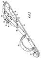
- the respective spring clips 14 and 16 which are identical one with the other, are formed from strip spring steel, and each include a central axially straight continuous portion 24, the central axially straight continuous portion 24 continuing at ono of its ends into an eyelet 20.
- the opposite end of the central axially straight continuous portion 24 proceeds into a bight 26, which, in Figure 1 extends through an aperture in the side wall of the tool 10.
- the bight 26 then continues into a first arm 28, the arm 28 terminating at its free end in a cutting point 30, whereby an elastomeric covering 32 providing a frictional grip on the shank 34 of the tool holder 10 easily can be pierced by the cutting point 30 by forcing the cutting point through the elastomeric covering from inside the tool holder 10 to allow the bight 26 of the clip 14 to be moved into the position shown in Figure 1.
- the eyelet 20 continues into a second at 36, which is accurately configured at 38 e.g. in a bight subtending somewhat over 180°C and having an opening to receive a member e.g. a pole, such as the pole 12, and be held in compressive frictional relation with respect to the outer surface of the pole upon closure of the spring clip, in this instance, the spring clip 16.
- a member e.g. a pole, such as the pole 12
- the second arm 36 At its free end, the second arm 36, as is later described, is provided with locking formations, enabling it to be locked to the first arm 28, thus to provide for locking of either the spring clip 14 or 16 in a closed position.
- the spring clip 14 In that closed position, the spring clip 14 is connected directly to the tool holder 10, and, by means of the leash 18 is connected directly to the spring clip 16, the spring clip 16 itself being firmly attached to the pole 12.
- the tool holder 10 works loose off the end of the pole 12, or is forcibly removed from the end of the pole 12 by an impact on the tool holder 10, the tool holder 10 remains directly attached to the pole 12 by the spring clips 14 and 16 and the interconnecting leash 18. The tool holder can then only fall by a distance which is that of the combined lengths of the spring clip 14 and the leash 18.
- Tool holders as used by window washers, commonly are provided with axially extending ribs 40 on their inner periphery, the purpose of those ribs being to permit the escape of air and water from the interior of the tool holder 10 upon insertion of the pole 12, and in order to improve the frictional grip of the tool holder 10 on the frusto-conical end 42 of the pole 12.
- the spring clip described here takes advantage of that construction by providing a spring clip, such as the spring clips 14 and 16 that are of a thickness no greater, and preferably less than the depth of the ribs 40, this allowing the central axially straight portion of the spring clip 14 to be positioned spaced from the frusto-conical surface 42 of the pole 12, and in a position in which it in no way interferes with she frictional grip of the ribs 40 on the frusto-conical portion 42.
- a spring clip such as the one 16 may be attached to the pole 12, and, a second spring clip such as the one 14 may be attached directly to the workman's tool belt.
- a spring clip such as the one 16 may be attached to the pole 12
- a second spring clip such as the one 14 may be attached directly to the workman's tool belt.
- the spring clip 16 may be attached to a rung of a ladder or a strut of scaffold on which the workman is standing, this, again resulting in the tool being tethered in its entirety and prevented from free fall.
- tee spring clip 14 can be configured for it to be attached to a tool of any other shape, such as a plumber's wrench, a screw driver, pliers, scrapers, paint rollers, sanding blocks and the like such as are used by workmen in other trades, the opportunity existing either of inserting the spring clip 14 into an eyelet of the tool, or, clamping the spring clip 14 to a shank of the tool by means of the arcuate portion 38.
- a window washer's squeegee or washing tool would be attached to the threaded shank 44, that threaded shank being useable, for example, by painters for threading into the handle of a paint roller or a paint scraper, or, into the shoe of a sanding block, such as is commonly used by painters or wall board papers.
- the spring clip and tether arrangement provides for the attachment of any hand-held tool to another member, such that the hand-held tool, if dropped by the workman, is tethered against free-fall, and thus, does not pose a hazard to persons positioned beneath the workman.
- the arms 28 and 36 are not in axial alignment with the axially straight central portion 24, the first arm 28 being displaced at an angle in one direction relative to the central portion 24, the second arm 36 being displaced in an opposite direction relative to the central portion 24, such that, in the initial position of the spring clip, the arms 28 and 36 extend substantially parallel to one another in side-by-side relation, and, at an angle to the central portion 24.
- the arms 28 and 36 are pushed in opposite directions as indicated by the arrows A, this acting to reversely stress the arms 28 and 36 against a strong spring bias, as provided by the body of the spring clip itself.
- the arm 36 is then depressed downwardly towards the arm 28, until locking indentations 46 positioned on opposite sides of a curved crown portion 50 of the first arm 28 are moved into alignment with corresponding locking indentations 48 formed in the second arm 36, and, which define a central tooth 52 on the second arm 36. Lateral pressure own the arms 28 and 36 is then removed, this permitting the tooth 52 of the second arm 36 to pass beneath the curved crown portion 50 of the arm 28, which is permitted by the locking indentations 46 and 48.
- the arms 28 and 36 then assume an in-line position in which they extend parallel to the central portion 24, the arms 28 and 36 having moved in the directions of the arrows B in Figure 4, but not having returned completely to their initial position as illustrated in Figure 2, the arms 28 and 36, thus are under a spring bias acting in the directions of the arrows B, this acting to lock the spring clip in its closed position, and acting to prevent unintentional release and opening of the spring clip.
- the locking interengagement of the arms 36 and 28 can be further improved as illustrated in Figs. 11 through 15 by forming the free end 56 of the arm 36 with a detent 58 which can ride over the arm 28 during closure of the spring clip, and, which in the fully closed position of the spring clip becomes seated in a locking recess 60 formed in the arm 28.
- the spring clip cannot be unlocked, unless, as illustrated in Fig. 16, a screwdriver or other pointed instrument 62 is inserted beneath the free end of the second arm 36 and on top of the first arm 28, the screwdriver 62 then being employed to pry and lift the detent 58 out of the locking recess 60, this then permitting release of the arms 28 and 36 relative to each other by moving them in opposite lateral directions.
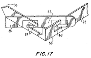
- Figure 17 illustrates an alternative method of locking the arms 28 and 36 to each other.
- the respective arms 28 and 36 are provided with intermeshing fingers 64, which intermesh upon closing of the spring clip, the axially directed forces stored in the respective arms 36 and 28 then acting to draw the arms 28 and 36 in opposite axial directions in order to intermesh the fingers 64 in the manner illustrated in Figure 17.
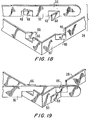
- the tabs 68 are bent for them to lie parallel to adjacent surfaces of the first arm 28 when the clip is in a fully locked position, and, the tabs 66 of the arm 28 similarly are bent for them to lie parallel to the arm 36.
- the spring clip is locked in its closed position, and, is highly resistant to unlocking of the spring clip under random impact imposed on the spring clip in the event that the tool with its associated spring clip accidentally is dropped, and impacted on projecting members such as window lodges, scaffolding members, ladder rungs and such similar members that may be in the path of free fall of the tool.
Landscapes
- Engineering & Computer Science (AREA)
- General Engineering & Computer Science (AREA)
- Mechanical Engineering (AREA)
- Clamps And Clips (AREA)
Applications Claiming Priority (2)
| Application Number | Priority Date | Filing Date | Title |
|---|---|---|---|
| US08/224,760 US5429289A (en) | 1994-04-08 | 1994-04-08 | Safety leash |
| US224760 | 1994-04-08 |
Publications (1)
| Publication Number | Publication Date |
|---|---|
| EP0676167A1 true EP0676167A1 (de) | 1995-10-11 |
Family
ID=22842074
Family Applications (1)
| Application Number | Title | Priority Date | Filing Date |
|---|---|---|---|
| EP95302364A Withdrawn EP0676167A1 (de) | 1994-04-08 | 1995-04-10 | Federbefestigungsclip |
Country Status (2)
| Country | Link |
|---|---|
| US (1) | US5429289A (de) |
| EP (1) | EP0676167A1 (de) |
Families Citing this family (16)
| Publication number | Priority date | Publication date | Assignee | Title |
|---|---|---|---|---|
| US5639049A (en) * | 1996-05-08 | 1997-06-17 | Jennings; Gilbert M. | Compact cable clip for retainment of cables and tubing |
| US5784762A (en) * | 1997-01-22 | 1998-07-28 | Huntting; Leonard M. | Trellis wires tieing clips used when controlling the direction of growth and the support of plant foliage of a crop |
| US6109491A (en) * | 1997-12-17 | 2000-08-29 | Aronson; Gina E. | Socket retainer and utility belt for using same |
| US6679404B2 (en) * | 2001-02-28 | 2004-01-20 | Mark R. Brandt | Tool-toting device for connection to a belt |
| USD514310S1 (en) * | 2002-06-21 | 2006-02-07 | Roye Michael E | Key chain clip |
| USD488924S1 (en) | 2002-12-17 | 2004-04-27 | Hal W. Miller | Padded shoulder sling strap for cordless tools |
| US20070278270A1 (en) * | 2006-05-30 | 2007-12-06 | Sergio Castaneda | Quick release locking belt clip mechanism for engaging portable electronic devices |
| US20090065538A1 (en) * | 2007-08-03 | 2009-03-12 | Jeff Rodriquez | Sanding Block Leash |
| US8413764B1 (en) | 2009-09-29 | 2013-04-09 | David A. Cohen | Ladder safety device, systems and methods of arresting falls from ladders |
| FR2993152B1 (fr) * | 2012-07-13 | 2015-09-04 | Delta Composants | Accessoire destine a etre accroche sur une sangle, comprenant deux languettes susceptibles d'exercer un effet de pincement |
| USD713282S1 (en) * | 2013-10-31 | 2014-09-16 | Colleen Finnegan | Dry erase bracelet |
| US9797420B2 (en) * | 2014-02-10 | 2017-10-24 | Cloop, Llc | Elongate attachable flexible magnetic article holder |
| USD796300S1 (en) * | 2014-11-25 | 2017-09-05 | Tenacious Holdings, Inc. | Lock clip |
| WO2019040301A1 (en) * | 2017-08-22 | 2019-02-28 | Illinois Tool Works Inc. | MUTUAL LOCKING CLAMPS |
| US10524877B2 (en) | 2017-11-09 | 2020-01-07 | Marc Appelbaum | Dental implant screwdriver harness system |
| US10517693B2 (en) | 2017-11-09 | 2019-12-31 | Marc Appelbaum | Dental implant screwdriver harness system |
Citations (4)
| Publication number | Priority date | Publication date | Assignee | Title |
|---|---|---|---|---|
| US4416038A (en) * | 1982-05-24 | 1983-11-22 | Adecon, Inc. | Balloon clip |
| GB2197019A (en) * | 1986-11-01 | 1988-05-11 | Stikits Limited | A clip |
| AT387312B (de) * | 1984-05-18 | 1989-01-10 | Glock Gaston | Haltespange |
| EP0645103A1 (de) * | 1993-09-25 | 1995-03-29 | Samuel Schlittler | Aufsteckhalterung für Schmuck und Abzeichen mit Sicherungsvorrichtung |
Family Cites Families (9)
| Publication number | Priority date | Publication date | Assignee | Title |
|---|---|---|---|---|
| US439423A (en) * | 1890-10-28 | Umbrella or cane holder | ||
| US1511704A (en) * | 1921-06-11 | 1924-10-14 | Buck Ainsworth | Window-cleaner's safety device |
| US1488594A (en) * | 1922-06-01 | 1924-04-01 | American Platinum Works | Lingerie clasp |
| US2354848A (en) * | 1941-09-27 | 1944-08-01 | Charles R Carpenter | Fish stringer and the like |
| US2628396A (en) * | 1950-10-05 | 1953-02-17 | Louis M Grimes | Bag closure |
| US3111734A (en) * | 1960-07-29 | 1963-11-26 | P & K Inc | Fish stringer |
| US3358484A (en) * | 1966-02-18 | 1967-12-19 | Scovill Manufacturing Co | Key retaining loop |
| US3519177A (en) * | 1968-07-09 | 1970-07-07 | Sweeny Voinovich | Key ring carrier |
| US4440334A (en) * | 1983-05-05 | 1984-04-03 | Coast Manufacturing Co., Inc. | Adjustable camera strap construction |
-
1994
- 1994-04-08 US US08/224,760 patent/US5429289A/en not_active Expired - Fee Related
-
1995
- 1995-04-10 EP EP95302364A patent/EP0676167A1/de not_active Withdrawn
Patent Citations (4)
| Publication number | Priority date | Publication date | Assignee | Title |
|---|---|---|---|---|
| US4416038A (en) * | 1982-05-24 | 1983-11-22 | Adecon, Inc. | Balloon clip |
| AT387312B (de) * | 1984-05-18 | 1989-01-10 | Glock Gaston | Haltespange |
| GB2197019A (en) * | 1986-11-01 | 1988-05-11 | Stikits Limited | A clip |
| EP0645103A1 (de) * | 1993-09-25 | 1995-03-29 | Samuel Schlittler | Aufsteckhalterung für Schmuck und Abzeichen mit Sicherungsvorrichtung |
Also Published As
| Publication number | Publication date |
|---|---|
| US5429289A (en) | 1995-07-04 |
Similar Documents
| Publication | Publication Date | Title |
|---|---|---|
| US5429289A (en) | Safety leash | |
| EP2008775B1 (de) | Abbruchwerkzeug | |
| CA1141107A (en) | Emergency rescue axe device | |
| AU2011224603B2 (en) | Pole climbing fall prevention assembly | |
| US5156233A (en) | Safety anchor for use with slotted beams | |
| US5428853A (en) | Fireman's combination tool assembly | |
| US4253218A (en) | Spring loaded ascender | |
| US8567290B2 (en) | Retrofit system for tethering a hand tool | |
| US6792829B2 (en) | Shingle lifting tool | |
| US20060075572A1 (en) | Multi-functional firefighter's tool | |
| US20080163464A1 (en) | Safety cable for holding tools | |
| US8567291B2 (en) | Retrofit system for tethering a hand tool | |
| US20190209878A1 (en) | Tensioning device | |
| US6718586B2 (en) | Interlocking striking tool handle | |
| US20080042029A1 (en) | Expansible, variable depth hole anchor | |
| US11844964B2 (en) | Multi-use rescue access bar | |
| AU2010100566A4 (en) | Scaffolding Hammer | |
| DE102016101651B4 (de) | Auf- und Abseilvorrichtung | |
| EP2864080B1 (de) | Nachrüstsystem zum anbinden eines handwerkzeugs | |
| DE102010009600B4 (de) | Griffschale für Werkzeuge | |
| EP1653830A2 (de) | Dehnbarer lochanker mit vergrössertem bremsfreigebenden schlagkopf | |
| AU2016202190A1 (en) | Scaffolding Hammer | |
| EP2239102A2 (de) | Zubehörteil für eine handgehaltene Werkzeugmaschine | |
| US11690440B1 (en) | Tool cuff device and method of use | |
| AU2015201600A1 (en) | Scaffolding Hammer |
Legal Events
| Date | Code | Title | Description |
|---|---|---|---|
| PUAI | Public reference made under article 153(3) epc to a published international application that has entered the european phase |
Free format text: ORIGINAL CODE: 0009012 |
|
| AK | Designated contracting states |
Kind code of ref document: A1 Designated state(s): DE FR GB |
|
| 17P | Request for examination filed |
Effective date: 19951113 |
|
| STAA | Information on the status of an ep patent application or granted ep patent |
Free format text: STATUS: THE APPLICATION IS DEEMED TO BE WITHDRAWN |
|
| 18D | Application deemed to be withdrawn |
Effective date: 19981103 |