EP0676294A2 - Tintenpatrone für einen Druckkopf eines Ink-Jet-Printers - Google Patents
Tintenpatrone für einen Druckkopf eines Ink-Jet-Printers Download PDFInfo
- Publication number
- EP0676294A2 EP0676294A2 EP95810218A EP95810218A EP0676294A2 EP 0676294 A2 EP0676294 A2 EP 0676294A2 EP 95810218 A EP95810218 A EP 95810218A EP 95810218 A EP95810218 A EP 95810218A EP 0676294 A2 EP0676294 A2 EP 0676294A2
- Authority
- EP
- European Patent Office
- Prior art keywords
- housing
- ink
- ink cartridge
- bore
- cartridge according
- Prior art date
- Legal status (The legal status is an assumption and is not a legal conclusion. Google has not performed a legal analysis and makes no representation as to the accuracy of the status listed.)
- Granted
Links
Images

Classifications
-
- B—PERFORMING OPERATIONS; TRANSPORTING
- B41—PRINTING; LINING MACHINES; TYPEWRITERS; STAMPS
- B41J—TYPEWRITERS; SELECTIVE PRINTING MECHANISMS, i.e. MECHANISMS PRINTING OTHERWISE THAN FROM A FORME; CORRECTION OF TYPOGRAPHICAL ERRORS
- B41J2/00—Typewriters or selective printing mechanisms characterised by the printing or marking process for which they are designed
- B41J2/005—Typewriters or selective printing mechanisms characterised by the printing or marking process for which they are designed characterised by bringing liquid or particles selectively into contact with a printing material
- B41J2/01—Ink jet
- B41J2/17—Ink jet characterised by ink handling
- B41J2/175—Ink supply systems ; Circuit parts therefor
- B41J2/17503—Ink cartridges
- B41J2/17513—Inner structure
Definitions
- a cartridge according to the preamble of claim 1 is known from EP-A-560 729. It has an opening on an end wall of a housing, into which a nozzle of a printhead can be inserted in a sealing manner. The end of the nozzle is closed off by a sieve, which compresses a foam body soaked with ink when it is inserted, so that ink is pressed into the nozzle.
- EP-A-560 729 additionally suggests installing an additional pump in the housing.
- this pump makes the ink cartridge more expensive.
- FIG. 1 shows a cross section through a printhead 1 with an exchangeable ink cartridge 2.
- the print head 1 has a nozzle plate with a plurality of narrow nozzles 3, each of which is assigned a thermoelectric heating element and which are connected to a tubular nozzle 5 via channels 4.
- the nozzle 5 is closed at the top by a sieve 6. If a heating element is heated at the moment, a gas bubble forms, and the excess pressure ejects a droplet of ink from the nozzle in question. After the gas bubble has collapsed, ink is drawn in from the nozzle 5 by the surface tension at the nozzle mouth. This mode of operation of the print head is known.
- the cartridge 2 is inserted into a rectangular tubular extension 7 of the print head 1 and secured with cooperating locking elements 8, 9.
- the cartridge 2 consists of a housing 15 and a cover 16.
- the bottom 17 of the housing 15 has a stepped bore 18 into which an elastomeric sealing plug 19 with a tubular wall 20 and a cover 21 connected in one piece is inserted.
- the cover 21 has predetermined breaking notches 22, which are star-shaped in the example shown.
- a further, small cavity 27 is formed, which is ventilated through a ventilation opening.
- the ventilation opening is formed by a capillary gap between a relatively long bore 28 of the housing 15, into which a mandrel 29 of the cover 16, which is slightly smaller in diameter, is inserted.
- the cartridge 2 is closed by the cover 21 at the start of insertion into the head 1 and the cover 21 is only broken through by the connector 5 after the wall 20 of the sealing plug 19 has sealed off from the connector 5, this results in a simple and safe Handling. No opening needs to be cleared before inserting the cartridge 2 (eg by removing a sealing film). A drop from an opening is therefore not possible.
- the filter 25 reliably prevents any contamination of the ink from entering the nozzle 5 and thus into the narrow nozzles of the nozzle plate 3. It reduces it also the accumulation of particles on the screen 6 of the head 1, which would increase the flow resistance through the screen over time. This increases the life of the print head 1.
- a precisely dimensioned, narrow, capillary air supply opening is formed in a simple manner, which would otherwise be difficult to implement by injection molding.
- the narrow capillary ventilation opening largely prevents evaporation of the ink.
- the sealing plug 19 can also consist of this material and can be injection molded in one piece with the housing 15.
- the sealing plug 19 is sleeve-shaped and has no cover 21.
- a pin 33 is inserted into it from the inside, which has a tab 34 protruding on one side from the top.
- the free end 35 of the tab 34 is connected to the bottom 17 of the housing 15, for example welded.
- the bore 28 is extended downwards and the mandrel 29 is integrally formed on the print head 1.
- the bore 28 is closed by a thin membrane 40 which is penetrated by the mandrel 29 immediately before the latching elements 8, 9 snap into place.
- the mandrel 29 has a longitudinal groove 41 at the upper end in order to ensure a connection of the capillary gap between the bore 28 and the mandrel 29 and the cavity 27.
- the embodiment according to FIG. 6 has the same design as that according to FIGS. 1 or 5.
- the bore 28 is closed at the lower end with an elastomeric pin 42 which, when the cartridge 2 is inserted through the front end of the mandrel 29, immediately before the latching elements 8, 9 engage the bore 28 into the cavity 27 is pushed.
- the pin 42 acts as a piston when the cartridge 2 is inserted into the print head 1.
- an O-ring can be attached to the upper end of the mandrel 29, which seals when the cartridge 2 is inserted against the bore 28 and projects into the cavity 27 when the cartridge is fully inserted.
- the narrow, capillary gap formed by the relatively long bore 28 and the mandrel 29 used, but also the delimitation of the connector 5 from the foam body 24 by a filter 25 and a vestibule can also be used with other ink cartridges, the opening 26 of which is not covered by a cover 21 or 33 is completed, can be used sensibly with the corresponding effect.
Landscapes
- Ink Jet (AREA)
Abstract
Description
- Eine Patrone gemäss Oberbegriff des Anspruchs 1 ist aus der EP-A-560 729 bekannt. Sie hat an einer Stirnwand eines Gehäuses eine Oeffnung, in welche ein Stutzen eines Druckkopfs abdichtend eingesteckt werden kann. Der Stutzen ist stirnseitig durch ein Sieb abgeschlossen, das beim Einsetzen einen mit Tinte getränkten Schaumkörper etwas komprimiert, sodass Tinte in den Stutzen gedrückt wird. Es hat sich allerdings gezeigt, dass dies gelegentlich nicht ausreicht, sodass in der EP-A-560 729 zusätzlich vorgeschlagen wird, im Gehäuse zusätzlich eine Pumpe einzubauen. Diese Pumpe verteuert allerdings die Tintenpatrone.
- Der vorliegenden Erfindung liegt die Aufgabe zugrunde, eine Tintenpatrone der eingangs genannten Art derart auszubilden, dass sie in der Handhabung einfacher und sicherer ist. Diese Aufgabe wird durch die Merkmalskombination der Ansprüche gelöst. Nachfolgend wird ein Ausführungsbeispiel der Erfindung anhand der Zeichnungen erläutert. Darin zeigt:
- Figur 1
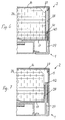
- einen Querschnitt durch einen Druckkopf und eine Tintenpatrone.
- Figur 2
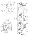
- eine perspektivische Darstellung der Einzelteile,
- Figur 3
- einen Schnitt durch den Stopfen,
- Figur 4
- eine Stirnansicht, und
- Figuren 5 bis 7
- drei weitere Ausführungsformen.
- In Figur 1 ist ein Querschnitt durch einen Druckkopf 1 mit einer auswechselbaren Tintenpatrone 2 dargestellt. Der Druckkopf 1 hat eine Düsenplatte mit mehreren engen Düsen 3, welchen je ein thermoelektrisches Heizelement zugeordnet ist, und die über Kanäle 4 mit einem rohrförmigen Stutzen 5 verbunden sind. Der Stutzen 5 ist oben durch ein Sieb 6 abgeschlossen. Wird ein Heizelement momentan erhitzt, bildet sich eine Gasblase, und durch den Ueberdruck wird ein Tintentröpfchen aus der betreffenden Düse ausgestossen. Nach dem Kollabieren der Gasblase wird durch die Oberflächenspannung an der Düsenmündung Tinte aus dem Stutzen 5 nachgesaugt. Diese Wirkungsweise des Druckkopfs ist bekannt. Die Patrone 2 ist in einen rechteckrohrförmigen Ansatz 7 des Druckkopfs 1 eingesteckt und mit zusammenwirkenden Rastelementen 8, 9 gesichert.
- Die Patrone 2 besteht aus einem Gehäuse 15 und einem Deckel 16. Der Boden 17 des Gehäuses 15 hat eine abgestufte Bohrung 18, in die ein elastomerer Dichtstopfen 19 mit einer rohrförmigen Wand 20 und einem einstückig damit verbundenen Deckel 21 eingesetzt ist. Der Deckel 21 hat Sollbruchkerben 22, die im dargestellten Beispiel sternförmig ausgebildet sind. Beim Einsetzen der Patrone 2 in den Druckkopf 1 dichtet die Innenseite 26 der Wand 20 gegenüber dem Stutzen 5 ab, bevor der Deckel 21 durch das Stirnende des Stutzens 5 durchstossen wird. Anschliessend ragt das Sieb 6 in einen mit freier Tinte gefüllten Vorraum 23, der gegenüber einem tintegetränkten Schaumkörper 24 durch ein Filter 25 abgegrenzt ist. An der dem Vorraum 23 gegenüberliegenden Kante des Gehäuses 15 ist ein weiterer, kleiner Hohlraum 27 gebildet, der durch eine Belüftungsöffnung belüftet ist. Die Belüftungsöffnung wird gebildet durch einen kapillaren Spalt zwischen einer relativ langen Bohrung 28 des Gehäuses 15, in welche ein im Durchmesser geringfügig kleinerer Dorn 29 des Dekkels 16 eingesteckt ist.
- Weil die Patrone 2 zu Beginn des Einsetzens in den Kopf 1 durch den Deckel 21 verschlossen ist und der Deckel 21 erst durch den Stutzen 5 durchbrochen wird, nachdem die Wand 20 des Dichtstopfens 19 gegenüber dem Stutzen 5 gedichtet hat, ergibt sich eine einfache und sichere Handhabung. Vor dem Einsetzen der Patrone 2 muss keine Oeffnung freigemacht werden (z.B. durch Entfernen einer Siegelfolie). Es ist daher kein Tropfen aus einer Oeffnung möglich. Das Filter 25 verhindert zuverlässig den Eintritt allfälliger Verunreinigungen der Tinte in den Stutzen 5 und damit in die engen Düsen der Düsenplatte 3. Es verringert auch die Kumulation von Partikeln auf dem Sieb 6 des Kopfes 1, was den Durchfluss-Widerstand durch das Sieb mit der Zeit erhöhen würde. Dadurch wird die Lebensdauer des Druckkopfs 1 erhöht. Durch die lange Bohrung 28 und den Dorn 29 wird auf einfache Weise eine genau dimensionierbare, enge, kapillare Luftzufuhröffnung gebildet, die anders spritzgiesstechnisch nur schwer zu realisieren wäre. Durch die enge kapillare Belüftungsöffnung wird ein Verdunsten der Tinte weitgehend vermieden.
- Falls das Gehäuse 15 aus einem relativ weichen Thermoplasten spritzgegossen wird, kann der Dichtstopfen 19 auch aus diesem Material bestehen und einstückig mit dem Gehäuse 15 spritzgegossen sein.
- Bei den nachfolgend beschriebenen Ausführungsbeispielen sind analoge Teile mit gleichen Bezugszeichen versehen, sodass sich eine detaillierte Erläuterung dieser Teile erübrigt.
- Bei der Ausführungsform nach Figur 5 ist der Dichtstopfen 19 hülsenförmig und hat keinen Deckel 21. Dafür ist in ihn von der Innenseite her ein Zapfen 33 eingesteckt, der auf der Oberseite einen einseitig abstehenden Lappen 34 hat. Das freie Ende 35 des Lappens 34 ist mit dem Boden 17 des Gehäuses 15 verbunden, z.B. verschweisst. Beim Einstecken des Stutzens 5 schiebt dessen Stirnende den Zapfen 33 vor sich her in den Vorraum 23. Der Lappen 34 verhindert, dass er bei eingeführtem Stutzen plan auf dessen Stirnfläche aufliegen und ihn verstopfen kann. Mit der Ausführungsform nach Figur 5 wird ein Lufteintritt in den Vorraum 23 beim Einstecken des Stutzens 5 vollständig vermieden.
- Bei der Ausführungsform nach Figur 6 ist die Bohrung 28 nach unten verlängert und der Dorn 29 am Druckkopf 1 angeformt. Vor dem Einsetzen der Patrone 2 ist die Bohrung 28 durch eine dünne Membran 40 verschlossen, die beim Einsetzen durch den Dorn 29 unmittelbar vor dem Einrasten der Rastelemente 8, 9 durchstossen wird. Der Dorn 29 hat am oberen Ende eine Längsnut 41, um eine Verbindung des kapillaren Spaltes zwischen Bohrung 28 und Dorn 29 und dem Hohlraum 27 sicherzustellen. Im übrigen ist die Ausführungsform nach Figur 6 gleich ausgebildet wie jene nach Figuren 1 oder 5.
- Dadurch, dass der Stutzen 5 des Druckkopfs 1 in den Vorraum 23 eindringt, bevor die Entlüftungsöffnung geöffnet ist, entsteht in der Patrone 2 ein kleiner Ueberdruck, welcher bewirkt, dass der Stutzen 5 des Kopfs 1 zumindest teilweise mit Tinte gefüllt wird, was die Wiederinbetriebnahme des Druckkopfs 1 erleichtert.
- Bei der Ausführungsform nach Figur 7 ist im Neuzustand die Bohrung 28 am unteren Ende mit einem elastomeren Zapfen 42 verschlossen, der beim Einsetzen der Patrone 2 durch das Stirnende des Dorns 29 unmittelbar vor dem Einrasten der Rastelemente 8, 9 aus der Bohrung 28 in den Hohlraum 27 geschoben wird. Der Zapfen 42 wirkt beim Einsetzen der Patrone 2 in den Druckkopf 1 als Kolben. Dadurch kann beim Einsetzen der Patrone ein höherer Ueberdruck erzeugt werden, und somit der Stutzen noch besser gefüllt werden. Dadurch wird es möglich, auf einen Spülprozess im Drucker zu verzichten, bevor der Druckkopf wieder in Betrieb genommen wird.
- Abweichend von der beschriebenen Ausführungsform kann am oberen Ende des Dorns 29 ein O-Ring befestigt sein, der beim Einsetzen der Patrone 2 gegenüber der Bohrung 28 abdichtet und bei vollständig eingesetzter Patrone in den Hohlraum 27 ragt.
- Der enge, kapillare Spalt gebildet durch die relativ lange Bohrung 28 und den eingesetzten Dorn 29, aber auch die Abgrenzung des Stutzens 5 vom Schaumkörper 24 durch ein Filter 25 und einen Vorraum können auch bei anderen Tintenpatronen, deren Oeffnung 26 nicht durch einen Deckel 21 bzw. 33 abgeschlossen ist, sinnvoll mit entsprechender Wirkung eingesetzt werden.
Claims (10)
- Tintenpatrone für einen Druckkopf eines Ink-Jet-Printers, umfassend ein allseits geschlossenes Gehäuse (15, 16) mit einer ersten Oeffnung (26) zur Aufnahme eines rohrförmigen Stutzens (5) des Druckkopfs (1) sowie einer zweiten Oeffnung (28, 29) für die Zufuhr von Luft zum Innenraum des Gehäuses (15, 16), wobei der Innenraum Tinte enthält, dadurch gekennzeichnet, dass die erste Oeffnung innerhalb einer als Dichtfläche (26) wirkenden Bohrung durch einen Deckel (21, 33) verschlossen ist, der beim Durchstecken des Stutzens (5) geöffnet wird.
- Tintenpatrone nach Anspruch 1, wobei der Deckel (21) einstückig an der Dichtfläche (26) angeformt ist und Sollbruchkerben (22) aufweist.
- Tintenpatrone nach Anspruch 2, wobei die Dichtfläche (26) und der Deckel (21) an einem elastomeren Stopfen (20) ausgebildet sind, der in eine Gehäusebohrung (18) eingesetzt ist.
- Tintenpatrone nach Anspruch 1, wobei der Deckel als in die Bohrung (26) eingesetzter Zapfen (33) ausgebildet ist, der auf der Innenseite einseitig über einen Lappen (34) am Gehäuse (15) befestigt ist.
- Tintenpatrone nach einem der Ansprüche 1-4, wobei auf der Innenseite des Deckels (21, 33) ein mit freier Tinte gefüllter Vorraum (23) angeordnet ist.
- Tintenpatrone nach Anspruch 5, wobei der Innenraum des Gehäuses (15, 16) einen mit Tinte getränkten Schaumkörper (24) enthält, der gegenüber dem Vorraum (23) durch ein Filter (25) begrenzt ist.
- Tintenpatrone nach einem der Ansprüche 1-6, wobei das Gehäuse (15, 16) aus zwei Teilen, nämlich einem Gehäusekörper (15) und einem Deckelement (16) besteht, und wobei die zweite Oeffnung durch eine längliche Bohrung (28) in einem der Teile (15) gebildet ist, in welche ein am andern Teil (16) angeformter Dorn (29) mit geringem Spiel eingesteckt ist.
- Tintenpatrone nach einem der Ansprüche 1-6, wobei die zweite Oeffnung durch eine längliche Bohrung (28) im Gehäuse (15, 16) gebildet ist, in welche bei eingesetzter Patrone (2) ein am Druckkopf (1) angeformter Dorn (29) mit geringem Spiel eingesteckt ist.
- Tintenpatrone nach Anspruch 8, wobei die Bohrung (28) im Neuzustand durch eine Membran (40) verschlossen ist, welche beim Einsetzen der Patrone (2) durch das Stirnende des Dorns (29) durchstossen wird.
- Tintenpatrone nach Anspruch 8, wobei der Dorn (29) beim Einsetzen der Patrone als Kolbenstange wirkt, die ein Dichtelement (42) längs der Bohrung (28) in einen Hohlraum (27) des Gehäuses (15, 16) einschiebt und als Pumporgan wirkt.
Applications Claiming Priority (2)
| Application Number | Priority Date | Filing Date | Title |
|---|---|---|---|
| DE9405723U DE9405723U1 (de) | 1994-04-06 | 1994-04-06 | Tintenpatrone für einen Druckkopf eines Ink-Jet-Printers |
| DE9405723U | 1994-04-06 |
Publications (3)
| Publication Number | Publication Date |
|---|---|
| EP0676294A2 true EP0676294A2 (de) | 1995-10-11 |
| EP0676294A3 EP0676294A3 (de) | 1998-01-07 |
| EP0676294B1 EP0676294B1 (de) | 2001-09-26 |
Family
ID=6906984
Family Applications (1)
| Application Number | Title | Priority Date | Filing Date |
|---|---|---|---|
| EP95810218A Expired - Lifetime EP0676294B1 (de) | 1994-04-06 | 1995-04-04 | Tintenpatrone für einen Druckkopf eines Ink-Jet-Printers |
Country Status (3)
| Country | Link |
|---|---|
| US (1) | US6074049A (de) |
| EP (1) | EP0676294B1 (de) |
| DE (2) | DE9405723U1 (de) |
Cited By (5)
| Publication number | Priority date | Publication date | Assignee | Title |
|---|---|---|---|---|
| US5619237A (en) * | 1994-08-24 | 1997-04-08 | Canon Kabushiki Kaisha | Replaceable ink tank |
| US5619239A (en) * | 1993-11-29 | 1997-04-08 | Canon Kabushiki Kaisha | Replaceable ink tank |
| US5821964A (en) * | 1996-07-24 | 1998-10-13 | Dataproducts Corporation | Cartridge for supplying liquid to a print head |
| US6270211B1 (en) | 1999-07-07 | 2001-08-07 | Lexmark International, Inc. | Bubble elimination and filter tower structure |
| US6398354B1 (en) | 1999-06-30 | 2002-06-04 | Lexmark International, Inc. | Printhead apparatus and printer having separate filtration device and method for attaching said device |
Families Citing this family (15)
| Publication number | Priority date | Publication date | Assignee | Title |
|---|---|---|---|---|
| DE29507743U1 (de) * | 1995-05-10 | 1996-09-12 | Pelikan Produktions Ag, Egg | Druckkopf für einen Ink-Jet-Printer |
| DE19604560C2 (de) * | 1996-02-08 | 1998-11-05 | Dia Nielsen Gmbh & Co Kg Zubeh | Adapter für auswechselbare Patronen |
| US6464338B1 (en) * | 1996-07-31 | 2002-10-15 | Canon Kabushiki Kaisha | Ink jet head with separable tank holding member and recording unit |
| JP3530684B2 (ja) * | 1996-07-31 | 2004-05-24 | キヤノン株式会社 | インクタンク |
| AU2003200319B2 (en) * | 1996-07-31 | 2005-11-24 | Canon Kabushiki Kaisha | An Ink Jet Recording Head, an Ink Jet Head Cartridge, and an Ink Jet Recording Apparatus |
| USD438241S1 (en) | 1999-05-28 | 2001-02-27 | Seiko Epson Corporation | Ink cartridge for printer |
| US6244697B1 (en) | 1999-06-30 | 2001-06-12 | Lexmark International, Inc. | Filter tower for ink jet printhead |
| USD446545S1 (en) | 1999-12-22 | 2001-08-14 | Nec Corporation | Ink cartridge |
| US6390615B1 (en) * | 2000-06-19 | 2002-05-21 | Xerox Corporation | Ink tank with securing means and seal |
| US6880925B2 (en) * | 2001-05-31 | 2005-04-19 | Canon Kabushiki Kaisha | Liquid discharge recording head, liquid discharge recording apparatus, and method for producing stopper member for liquid discharge recording head |
| KR100572780B1 (ko) * | 2001-09-19 | 2006-04-19 | 세이코 엡슨 가부시키가이샤 | 잉크 카트리지 및 그 제조 방법 |
| KR100452851B1 (ko) * | 2002-10-23 | 2004-10-14 | 삼성전자주식회사 | 적정 부압이 유지되는 잉크 카트리지 |
| KR100512987B1 (ko) * | 2003-01-16 | 2005-09-07 | 삼성전자주식회사 | 잉크카트리지 |
| US20040150698A1 (en) * | 2003-01-31 | 2004-08-05 | William Caro | Inkjet pen with removable lid |
| ITMI20031153A1 (it) * | 2003-06-06 | 2004-12-07 | Anteprima S R L | Sistema di alimentazione di inchiostro per stampanti a |
Family Cites Families (11)
| Publication number | Priority date | Publication date | Assignee | Title |
|---|---|---|---|---|
| JPS5859850A (ja) * | 1981-10-07 | 1983-04-09 | Nec Corp | インク受渡し装置 |
| US5182581A (en) * | 1988-07-26 | 1993-01-26 | Canon Kabushiki Kaisha | Ink jet recording unit having an ink tank section containing porous material and a recording head section |
| IT1232551B (it) * | 1989-07-13 | 1992-02-19 | Olivetti & Co Spa | Testina di stampa per una stampante termica a getto d'inchiostro |
| EP0519457B1 (de) * | 1991-06-19 | 1997-09-03 | Canon Kabushiki Kaisha | Tintenbehälter für Tintenstrahlaufzeichnungsgerät |
| JP3238756B2 (ja) * | 1992-08-31 | 2001-12-17 | キヤノン株式会社 | インクジェットカートリッジおよび記録装置 |
| SG46602A1 (en) * | 1992-01-28 | 1998-02-20 | Seiko Epson Corp | Ink tank cartridge and container therefor |
| DE59302549D1 (de) * | 1992-03-10 | 1996-06-20 | Pelikan Produktions Ag | Tintenpatrone für einen Druckkopf eines Ink-Jet-Printers |
| US5307091A (en) * | 1992-03-16 | 1994-04-26 | Lexmark International, Inc. | Jet ink refill supply |
| JPH06966A (ja) * | 1992-06-18 | 1994-01-11 | Fuji Xerox Co Ltd | インクジェットカートリッジ並びにこれに用いられるインクタンク及びインクジェットヘッド |
| JP3170380B2 (ja) * | 1993-02-17 | 2001-05-28 | 株式会社リコー | インクジェットプリンタ |
| IT1261876B (it) * | 1993-09-23 | 1996-06-03 | Olivetti Canon Ind Spa | Modulo di stampa a getto di inchiostro ricaricabile |
-
1994
- 1994-04-06 DE DE9405723U patent/DE9405723U1/de not_active Expired - Lifetime
-
1995
- 1995-04-04 DE DE59509626T patent/DE59509626D1/de not_active Expired - Lifetime
- 1995-04-04 EP EP95810218A patent/EP0676294B1/de not_active Expired - Lifetime
- 1995-04-06 US US08/417,869 patent/US6074049A/en not_active Expired - Fee Related
Cited By (15)
| Publication number | Priority date | Publication date | Assignee | Title |
|---|---|---|---|---|
| US6145975A (en) * | 1993-11-29 | 2000-11-14 | Canon Kabushiki Kaisha | Method of mounting an exchangeable ink container |
| US5619239A (en) * | 1993-11-29 | 1997-04-08 | Canon Kabushiki Kaisha | Replaceable ink tank |
| US6243116B1 (en) | 1993-11-29 | 2001-06-05 | Canon Kabushiki Kaisha | Ink container, installing-removing method therefore and apparatus usable with the same |
| US6070974A (en) * | 1993-11-29 | 2000-06-06 | Canon Kabushiki Kaisha | Ink jet unit for a detachably mountable ink container |
| US8425022B2 (en) | 1994-08-24 | 2013-04-23 | Canon Kabushiki Kaisha | Ink container for ink jet printer, holder for the container, carriage for the holder, and ink jet printer |
| US7914137B2 (en) | 1994-08-24 | 2011-03-29 | Canon Kabushiki Kaisha | Ink container for ink jet printer, holder for the container, carriage for the holder, and ink jet printer |
| US6336709B1 (en) | 1994-08-24 | 2002-01-08 | Canon Kabushiki Kaisha | Ink container for ink jet printer, holder for the container carriage for the holder and ink jet printer |
| US6361158B1 (en) | 1994-08-24 | 2002-03-26 | Canon Kabushiki Kaisha | Ink container for ink jet printing, holder for the container, carriage for the holder and ink jet printer |
| US5619237A (en) * | 1994-08-24 | 1997-04-08 | Canon Kabushiki Kaisha | Replaceable ink tank |
| US7401909B2 (en) | 1994-08-24 | 2008-07-22 | Canon Kabushiki Kaisha | Ink container for ink jet printer, holder for the container, carriage for the holder and ink jet printer |
| US7407275B2 (en) | 1994-08-24 | 2008-08-05 | Canon Kabushiki Kaisha | Ink container for ink jet printer, holder for the container, carriage for the holder and ink jet printer |
| US7407274B2 (en) | 1994-08-24 | 2008-08-05 | Canon Kabushiki Kaisha | Ink container for ink jet printer, holder for the container carriage for the holder and ink jet printer |
| US5821964A (en) * | 1996-07-24 | 1998-10-13 | Dataproducts Corporation | Cartridge for supplying liquid to a print head |
| US6398354B1 (en) | 1999-06-30 | 2002-06-04 | Lexmark International, Inc. | Printhead apparatus and printer having separate filtration device and method for attaching said device |
| US6270211B1 (en) | 1999-07-07 | 2001-08-07 | Lexmark International, Inc. | Bubble elimination and filter tower structure |
Also Published As
| Publication number | Publication date |
|---|---|
| EP0676294B1 (de) | 2001-09-26 |
| US6074049A (en) | 2000-06-13 |
| DE59509626D1 (de) | 2001-10-31 |
| EP0676294A3 (de) | 1998-01-07 |
| DE9405723U1 (de) | 1994-06-01 |
Similar Documents
| Publication | Publication Date | Title |
|---|---|---|
| EP0676294B1 (de) | Tintenpatrone für einen Druckkopf eines Ink-Jet-Printers | |
| DE69503683T2 (de) | Tintenstrahlkassettensystem für Farbstrahldrucker | |
| DE69317543T2 (de) | Tintennachfüllbehälter und Tintennachfüllverfahren unter Verwendung desselben | |
| DE69421455T2 (de) | Tintenstrahlschreiber mit hydrophober Barriere zur Tintenlecküberwachung | |
| DE69528397T2 (de) | Tintenkassette für einen Tintenstrahldrucker | |
| DE19534577C2 (de) | Tintenpatrone und Tintenstrahl-Aufzeichnungsgerät | |
| DE60311008T2 (de) | Verfahren zur Reinigung einer Druckkopfanordnung eines Tintenstrahlaufzeichnungsgerätes | |
| DE60203170T2 (de) | Tintenpatrone | |
| DE19545775C2 (de) | Flüssigkeitspatrone, insbesondere Tintenpatrone für einen Druckkopf eines Ink-Jet-Printers | |
| DE69710376T2 (de) | Ventilteil, Ventil, Tintenbehälter und Tintenstrahlkartusche mit diesem Behälter | |
| DE10341787B4 (de) | Tintenpatrone | |
| EP0560729A2 (de) | Tintenpatrone für einen Druckkopf eines Ink-Jet-Printers | |
| DE69716661T2 (de) | Tintenstrahlaufzeichnungsgerät und Tintenkartusche | |
| EP1247649A2 (de) | Vorrichtung zum Befüllen eines Tintentanks | |
| DE69802225T2 (de) | Tintenbehälter, Tintenstrahlpatrone, und Verfahren zum Füllen mit Tinte | |
| DE19549438C2 (de) | Flüssigkeitspatrone und Druckkopf für einen Ink-Jet-Printer | |
| DE2720092A1 (de) | Ventilanordnung | |
| DE69814941T2 (de) | Flüssigkeitsbehälter für Tintenstrahlkopf | |
| DE19614364B4 (de) | Druckkopf für einen Ink-Jet-Printer | |
| DE29706720U1 (de) | Nachfüllvorrichtung für einen Tintenstrahl-Druckkopf | |
| DE60102183T2 (de) | Tintenpatrone | |
| DE4235029C2 (de) | Deckel für einen Druckkopf eines Tintenstrahldruckers | |
| EP1556224B1 (de) | Tintenpatrone zum aufbringen auf einen aufzeichnungskopf | |
| WO2007003412A2 (de) | Tintenpatrone | |
| DE19618986B4 (de) | Tintenpatrone für einen Druckkopf eines Ink-Jet-Printers |
Legal Events
| Date | Code | Title | Description |
|---|---|---|---|
| PUAI | Public reference made under article 153(3) epc to a published international application that has entered the european phase |
Free format text: ORIGINAL CODE: 0009012 |
|
| AK | Designated contracting states |
Kind code of ref document: A2 Designated state(s): DE FR GB IT NL |
|
| PUAL | Search report despatched |
Free format text: ORIGINAL CODE: 0009013 |
|
| AK | Designated contracting states |
Kind code of ref document: A3 Designated state(s): DE FR GB IT NL |
|
| 17P | Request for examination filed |
Effective date: 19980509 |
|
| 17Q | First examination report despatched |
Effective date: 19990223 |
|
| GRAG | Despatch of communication of intention to grant |
Free format text: ORIGINAL CODE: EPIDOS AGRA |
|
| GRAG | Despatch of communication of intention to grant |
Free format text: ORIGINAL CODE: EPIDOS AGRA |
|
| GRAH | Despatch of communication of intention to grant a patent |
Free format text: ORIGINAL CODE: EPIDOS IGRA |
|
| RAP1 | Party data changed (applicant data changed or rights of an application transferred) |
Owner name: PELIKAN HARDCOPY PRODUCTION AG |
|
| GRAH | Despatch of communication of intention to grant a patent |
Free format text: ORIGINAL CODE: EPIDOS IGRA |
|
| GRAA | (expected) grant |
Free format text: ORIGINAL CODE: 0009210 |
|
| AK | Designated contracting states |
Kind code of ref document: B1 Designated state(s): DE FR GB IT NL |
|
| REF | Corresponds to: |
Ref document number: 59509626 Country of ref document: DE Date of ref document: 20011031 |
|
| REG | Reference to a national code |
Ref country code: GB Ref legal event code: IF02 |
|
| GBT | Gb: translation of ep patent filed (gb section 77(6)(a)/1977) |
Effective date: 20011201 |
|
| ET | Fr: translation filed | ||
| PLBE | No opposition filed within time limit |
Free format text: ORIGINAL CODE: 0009261 |
|
| STAA | Information on the status of an ep patent application or granted ep patent |
Free format text: STATUS: NO OPPOSITION FILED WITHIN TIME LIMIT |
|
| 26N | No opposition filed | ||
| PGFP | Annual fee paid to national office [announced via postgrant information from national office to epo] |
Ref country code: NL Payment date: 20070417 Year of fee payment: 13 |
|
| PGFP | Annual fee paid to national office [announced via postgrant information from national office to epo] |
Ref country code: IT Payment date: 20080428 Year of fee payment: 14 |
|
| PGFP | Annual fee paid to national office [announced via postgrant information from national office to epo] |
Ref country code: FR Payment date: 20080418 Year of fee payment: 14 |
|
| PGFP | Annual fee paid to national office [announced via postgrant information from national office to epo] |
Ref country code: GB Payment date: 20080423 Year of fee payment: 14 |
|
| NLV4 | Nl: lapsed or anulled due to non-payment of the annual fee |
Effective date: 20081101 |
|
| PG25 | Lapsed in a contracting state [announced via postgrant information from national office to epo] |
Ref country code: NL Free format text: LAPSE BECAUSE OF NON-PAYMENT OF DUE FEES Effective date: 20081101 |
|
| GBPC | Gb: european patent ceased through non-payment of renewal fee |
Effective date: 20090404 |
|
| REG | Reference to a national code |
Ref country code: FR Ref legal event code: ST Effective date: 20091231 |
|
| PG25 | Lapsed in a contracting state [announced via postgrant information from national office to epo] |
Ref country code: GB Free format text: LAPSE BECAUSE OF NON-PAYMENT OF DUE FEES Effective date: 20090404 Ref country code: FR Free format text: LAPSE BECAUSE OF NON-PAYMENT OF DUE FEES Effective date: 20091222 |
|
| PG25 | Lapsed in a contracting state [announced via postgrant information from national office to epo] |
Ref country code: IT Free format text: LAPSE BECAUSE OF NON-PAYMENT OF DUE FEES Effective date: 20090404 |
|
| REG | Reference to a national code |
Ref country code: DE Ref legal event code: R082 Ref document number: 59509626 Country of ref document: DE Representative=s name: MEISSNER, BOLTE & PARTNER GBR, DE |
|
| REG | Reference to a national code |
Ref country code: DE Ref legal event code: R082 Ref document number: 59509626 Country of ref document: DE Representative=s name: MEISSNER, BOLTE & PARTNER GBR, DE Effective date: 20120116 Ref country code: DE Ref legal event code: R081 Ref document number: 59509626 Country of ref document: DE Owner name: PELIKAN HARDCOPY PRODUCTION AG, CH Free format text: FORMER OWNER: PELIKAN HARDCOPY PRODUCTION AG, EGG, CH Effective date: 20120116 |
|
| PGFP | Annual fee paid to national office [announced via postgrant information from national office to epo] |
Ref country code: DE Payment date: 20120620 Year of fee payment: 18 |
|
| REG | Reference to a national code |
Ref country code: DE Ref legal event code: R084 Ref document number: 59509626 Country of ref document: DE Effective date: 20120703 |
|
| PG25 | Lapsed in a contracting state [announced via postgrant information from national office to epo] |
Ref country code: DE Free format text: LAPSE BECAUSE OF NON-PAYMENT OF DUE FEES Effective date: 20131101 |
|
| REG | Reference to a national code |
Ref country code: DE Ref legal event code: R119 Ref document number: 59509626 Country of ref document: DE Effective date: 20131101 |