EP0676310A2 - Zigarettenanzünder, vorzugsweise für Kraftfahrzeuge - Google Patents
Zigarettenanzünder, vorzugsweise für Kraftfahrzeuge Download PDFInfo
- Publication number
- EP0676310A2 EP0676310A2 EP94120243A EP94120243A EP0676310A2 EP 0676310 A2 EP0676310 A2 EP 0676310A2 EP 94120243 A EP94120243 A EP 94120243A EP 94120243 A EP94120243 A EP 94120243A EP 0676310 A2 EP0676310 A2 EP 0676310A2
- Authority
- EP
- European Patent Office
- Prior art keywords
- ring
- cigar lighter
- lighter
- bimetallic strip
- ignition body
- Prior art date
- Legal status (The legal status is an assumption and is not a legal conclusion. Google has not performed a legal analysis and makes no representation as to the accuracy of the status listed.)
- Granted
Links
Images




Classifications
-
- B—PERFORMING OPERATIONS; TRANSPORTING
- B60—VEHICLES IN GENERAL
- B60N—SEATS SPECIALLY ADAPTED FOR VEHICLES; VEHICLE PASSENGER ACCOMMODATION NOT OTHERWISE PROVIDED FOR
- B60N3/00—Arrangements or adaptations of other passenger fittings, not otherwise provided for
- B60N3/14—Arrangements or adaptations of other passenger fittings, not otherwise provided for of electrically-heated lighters
-
- B—PERFORMING OPERATIONS; TRANSPORTING
- B60—VEHICLES IN GENERAL
- B60Q—ARRANGEMENT OF SIGNALLING OR LIGHTING DEVICES, THE MOUNTING OR SUPPORTING THEREOF OR CIRCUITS THEREFOR, FOR VEHICLES IN GENERAL
- B60Q3/00—Arrangement of lighting devices for vehicle interiors; Lighting devices specially adapted for vehicle interiors
- B60Q3/20—Arrangement of lighting devices for vehicle interiors; Lighting devices specially adapted for vehicle interiors for lighting specific fittings of passenger or driving compartments; mounted on specific fittings of passenger or driving compartments
- B60Q3/275—Smoking-related fittings, e.g. cigarette lighters or ashtrays
-
- B—PERFORMING OPERATIONS; TRANSPORTING
- B60—VEHICLES IN GENERAL
- B60Q—ARRANGEMENT OF SIGNALLING OR LIGHTING DEVICES, THE MOUNTING OR SUPPORTING THEREOF OR CIRCUITS THEREFOR, FOR VEHICLES IN GENERAL
- B60Q3/00—Arrangement of lighting devices for vehicle interiors; Lighting devices specially adapted for vehicle interiors
- B60Q3/60—Arrangement of lighting devices for vehicle interiors; Lighting devices specially adapted for vehicle interiors characterised by optical aspects
- B60Q3/62—Arrangement of lighting devices for vehicle interiors; Lighting devices specially adapted for vehicle interiors characterised by optical aspects using light guides
- B60Q3/64—Arrangement of lighting devices for vehicle interiors; Lighting devices specially adapted for vehicle interiors characterised by optical aspects using light guides for a single lighting device
-
- F—MECHANICAL ENGINEERING; LIGHTING; HEATING; WEAPONS; BLASTING
- F23—COMBUSTION APPARATUS; COMBUSTION PROCESSES
- F23Q—IGNITION; EXTINGUISHING-DEVICES
- F23Q7/00—Incandescent ignition; Igniters using electrically-produced heat, e.g. lighters for cigarettes; Electrically-heated glowing plugs
Definitions
- the present invention relates to cigar lighters, in particular for motor vehicles.
- a cigar lighter comprises a light conducting ring or lighting ring, an ignition body provided with a bimetallic strip, and a removable heating plug housed in the ignition body.
- the ignition body is usually able to be fixed to a wall of the vehicle.
- This body has a bottom from which protrude outwardly from the tabs for feeding cigarette lighter.
- One of the tabs is in contact with the ignition body.
- the ring For its fixing in a fixed wall of the vehicle, the ring is provided with mounting means for cooperation with complementary mounting means carried by a wall secured to the vehicle.
- the ignition body also carries a bimetallic strip intended to receive the heating plug, which is automatically ejected when the resistance which it carries is hot.
- the object of the present invention is to create security.
- a safety device is established, the safety tab being able to cooperate with the supply tab in contact with the ignition body for establishing a short circuit.
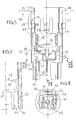
- the ignition body 19 serves as a receptacle for the heating plug 1 and is coupled to the ring 40.
- the body 19 has engagement means 24, here in the form of steps, for cooperation with complementary engagement means 24 ′, here in the form of notches, which the illuminating ring 40 has for this purpose.
- the ring 40 in translucent plastic material and electrically insulating, has mounting means 42 for mounting in the wall 80 having for this additional mounting means.
- These means here consist of two diametrically opposite openings 42 capable of cooperating with recesses 84 carried by the wall 80.
- This ring 40 has a flange 48 and thus once snapped in, the latter is immobilized in rotation by the redents 84 and in translation in one direction by the redents 84 and in the other direction by its flange 48.
- the ignition body 19 of annular shape here cylindrical with circular section, has two tongues 22, with hooks or notches 23, diametrically opposite, suitable for the attachment of the cigar lighter plug 1.
- This body 19 is made of electrically conductive material, here metallic.
- this body 19 is threaded into the ring 40 and is immobilized by the latter due to the presence of the redents 24 and the flange 25.
- the lighting ring 40 extends beyond the bottom 26 of the ignition body 19 and it has, externally to the ignition body 19, a free end forming a first part 46, 47 of a device for connecting the tongues 50, 51 the cigarette lighter.
- the ring 40 is of tubular shape complementary to that of the body 19 and has a drilled bottom 47, for the passage of supply tongues 50,51.
- This bottom 47 extends outwards, in the radial size (here diametral) of the ring 40, by a wall 46 of axial orientation suitable for cooperating with a second complementary part 70 of connector carried by the vehicle for formation of 'a connector.
- the end of the ring 40 having the bottom 47 and the wall 46, forming a blind hole will be called the free end as opposed to the end 48 coming into contact with the wall 80.
- the wall 80 has axially a hollow protuberance, of shape complementary to the ring 40, closed by a bottom 81.
- This protuberance has two diametrically opposite openings 85 and its bottom 81 is open for snap-fitting mounting of the body of the second part 70 of the connector having for this purpose notches 71.
- the ring 40 has two grooves 44 adapted to the dimensions of the recesses 84, said grooves 44 extending from the free end of the ring 40 to openings 49 provided for releasing the bimetallic strip 28 which is provided with the ignition body 19
- the bimetallic strip is mounted inside the ignition body 19 (FIGS. 5,7,10) and has two blades with orientation notches. axial for hooking with the heating plug of the cigar lighter and sound heating heater.
- the bimetallic strip 28 has a U-shaped section ( Figures 5,7,10).
- This ring 40 also has a longitudinal tongue 41 for cooperation with a groove 83 in the wall 80.
- the bottom 47 and the wall 46 delimit a first part of the connector and it is possible to assemble the ring 40, the ignition body 19 and the plug 1 in a production unit, then mount this unitary assembly at the manufacturer by simple axial threading, the redents 84 and the groove 83 forming a polarizing device, so that the connection parts 46 and 70 are automatically mounted one inside the other, the first part 46, 47 constituting the female part, while the second part 70 constitutes the male part.
- tongue 41 and the grooves 44 constitute guide means cooperating with the complementary guide means of the wall 80 formed by the recesses 84 and the groove 83.
- the lamp 54 is housed inside the contour of the ring 40.
- this housing 45 consists of a blind hole, open in the opposite direction to the bottom 47 just like the wall 46, and for its supply there is provided, on the one hand, a tongue 52 suitable for being connected to the positive terminal of the battery, the part 70 being arranged accordingly (FIG. 2), and, on the other hand, a tongue 53 described below in contact with the ignition body 19 itself connected to ground or to the negative terminal of the battery by the tongue 51.
- the bimetallic strip 28 is provided according to the invention with a safety tab 29, the said bimetallic strip 28 being carried by the ignition body 19 and assembled therewith by means of a fixing member 30 here a notched head screw for self-cleaning, as described below.
- the safety tab 29 passes through the bottom 26 of the ignition body 19 by means of a hole not referenced in FIG. 3 and in FIG. 7. It is surrounded by the lighting ring 40 (FIGS. 3 and 7).
- the second part of the connector 170 may not be fixed to the wall 180, the latter then simply having an opening 181, with the aid of which redents 84 and the groove 83 are formed.
- the lighting ring 40 - ignition body 19 - heating plug 1 (not shown here for simplification) assembly is assembled with the second part 170 of the connector, then the whole is threaded into the opening 181.
- this opening 181 is formed by means of an annular sleeve of axial orientation, the teeth 84 being arranged at the end of said sleeve.
- ring 40 is surrounded by a protective fairing 63.
- the tongue 50 has a tortuous shape and has a threaded hole, as visible in FIGS. 5 and 7 formed in a transverse part with respect to the current part of the tongue extending axially and crossing the bottom 47 in favor of a opening that presents said background.
- the threaded hole is suitable for receiving a fixing screw 30.
- This transverse part is engaged in a recess of the isolation ring 61, said ring 61 carrying a transverse part belonging to the tongue 51 placed side by side with respect to the tongue 50 (FIG. 7).
- the tongue 51 also passes axially through the bottom 47 by means of an opening and it is crossed by the ring 61.
- the transverse part of the tongue 51 is in contact with the bottom 26 and extends outside the body 19.
- the screw 30, by its head, is supported on the bimetallic strip 28 and comes to tighten the assembly 28-60-26-51-61-50 after crossing the parts 28-60,61 having openings for this purpose, so that said assembly is integral with body 19, the bottom 26 of which is pierced for this purpose, the ring 61 penetrating into said opening, as visible in FIGS. 5 and 7.
- the bimetallic strip 28 carries a safety tab 29 carrying a contact pad capable of cooperating with a part 56 of axial orientation ( Figures 3 and 7) of the tab 51 for establishment of a short circuit.
- This tongue 29 extends axially in the opposite direction to the blades of the bimetallic strip 28 intended to receive the heating plug 1 pressed into the body 19, for heating the latter which is automatically ejected when the resistance which it carries is hot.
- the wall 46 surrounds the tongues 50, 51 and is here in the form of a cross (FIG. 6).
- this wall 46 is laterally flanked by a wall 90 (FIG. 6) and a portion 94 of the ring 40, in which the housing 45 is formed.
- the wall 90 is connected to the upper and lower parts of the wall 46 by connection portions and it also has a portion in the form of a circular sector in the extension of the periphery of the ring 40.
- portion 94 constitutes a spacer between the walls 90, 46 and that it advantageously stiffens said walls.
- the housing 45 is formed in a stiffening rib of the first part 46, 47 of the connector.
- the lamp 54 is a long-life lamp and carries wires 55 welded to supply tabs 52, 53, the tongue 53 extends into the cavity 92 and is connected to the body 19 as visible in FIG. 9.
- this tongue 53 crosses the ring 40 while being anchored therein. It is allowed to deform when the body 19 is pressed into the ring 40, to be thus connected to the negative terminal of the battery, which simplifies connections.
- the tongue 52 is folded and is suitable for being connected by the connector 170 to the positive terminal of the battery.
- the tongue 51 has two wings 62, with the end folded in the axial direction, and that these serve as a polarizing device (FIG. 8).
- the assembly is carried out as follows: We start by mounting the tongue 50 by threading it into the bottom hole 47, then we place the ring 61 with a hollow with a generally rectangular outline, then we mount the tongue 51 on the ring 61 by engaging it laterally by making it penetrate into the opening in the bottom 47, the ignition body 19 is mounted, the latter being automatically indexed by the tongues 62 which guide it, then the ring 60 and the bimetallic strip 28 are mounted, the tongue 29 then being suitably positioned and finally the fixing is carried out using the screw 30.
- the ring 40 is made of electrically insulating material and the bottom 47 participates in maintaining the 50.51 tabs, which provides robustness to the cigar lighter.
- This pin 130 belongs to a part 31 in the form of a cup and it is erected from the bottom of said part 31 while being carried by the ignition body 19.
- This part 31 serves as assembly parts and plays the role of the screw 30 of the previous figures.
- its axially oriented peripheral part has a shoulder 34, produced by folding, and a locking shoulder 35.
- the shoulder 34 serves as a support for a stapling tab, which has the tab 150 connected to the positive terminal.
- the body 19 is mounted on the ring 61, then the ring 60 is threaded and finally the bimetallic strip 28, the assembly being held in place by deformation of the free end of the part 31 and formation of the shoulder 35.
- peripheral portion of the part 31 therefore crosses the rings 60, 61 the body 19 and the bimetallic strip 28.
- the head of the central spindle projects slightly axially with respect to the shoulder 35 and the plane of the bimetallic strip 28.
- the spindle 130 therefore extends generally towards the outside of the body 19 while being protected by the ring 40 and supported by the bottom 47.
- This socket comprises an insulating body 4, in two half-shells, with a tail 15 'and a nose 15 of reduced diameter.
- the two half-shells are held together by an elastic clamping collar 5 implanted at the level of the tail 15 'and by a first conductive element 2 enveloping said body.
- This element 2 has a hooking rim 3 capable of cooperating with the tongues 22.
- This sheet has a pin 9 which is elastically deformable, being here split into jaws by slots.
- the size of the internal bore of pin 9 is a function of that of pin 130 so that intimate and energetic contact takes place between said pins. This contact being favored by the ring 10.
- mounting means 42,84 and the guide means 83,41,44,84 can be different, and the structures can be reversed.
- the grooves 44 may belong to the wall 80, 180, the ring 40 then carrying two ribs for cooperation with said grooves 44, each rib being provided with a recess 84 capable of cooperating with a corresponding hole made in the groove of the wall.
- the structure of the engagement means can be reversed, the body 19 having holes, possibly axially staggered, for cooperation with projections carried internally by the ring 40.
- the pin 130 may be full and be attached to the bottom of the part 131.
- the spindle 130 can be separate from the part 131, then being reduced to a simple rivet fixing the parts 150, 61, 152, 60 and 28 to the bottom 26.
- This pin with a penetrating head in the form of a warhead, half-olives or frustoconical, can then be attached to the bottom 47 and be connected to the tongue 150.
- This pin is then placed inside a well delimited by said part 131.
- the body 19 and the ring 40 can be cylindrical with a square section.
Landscapes
- Engineering & Computer Science (AREA)
- Mechanical Engineering (AREA)
- Transportation (AREA)
- Chemical & Material Sciences (AREA)
- Combustion & Propulsion (AREA)
- General Engineering & Computer Science (AREA)
- Coupling Device And Connection With Printed Circuit (AREA)
- Arrangement Of Elements, Cooling, Sealing, Or The Like Of Lighting Devices (AREA)
- Lighters Containing Fuel (AREA)
Applications Claiming Priority (3)
| Application Number | Priority Date | Filing Date | Title |
|---|---|---|---|
| FR8916702A FR2655927B1 (fr) | 1989-12-18 | 1989-12-18 | Allume-cigare, notamment pour vehicules automobiles. |
| FR8916702 | 1989-12-18 | ||
| EP90403590A EP0434519B1 (de) | 1989-12-18 | 1990-12-14 | Zigarettenanzünder, vorzugsweise für Kraftfahrzeuge |
Related Parent Applications (2)
| Application Number | Title | Priority Date | Filing Date |
|---|---|---|---|
| EP90403590A Division EP0434519B1 (de) | 1989-12-18 | 1990-12-14 | Zigarettenanzünder, vorzugsweise für Kraftfahrzeuge |
| EP90403590.4 Division | 1990-12-14 |
Publications (3)
| Publication Number | Publication Date |
|---|---|
| EP0676310A2 true EP0676310A2 (de) | 1995-10-11 |
| EP0676310A3 EP0676310A3 (de) | 1996-02-07 |
| EP0676310B1 EP0676310B1 (de) | 1998-03-18 |
Family
ID=9388612
Family Applications (2)
| Application Number | Title | Priority Date | Filing Date |
|---|---|---|---|
| EP94120243A Expired - Lifetime EP0676310B1 (de) | 1989-12-18 | 1990-12-14 | Zigarettenanzünder, vorzugsweise für Kraftfahrzeuge |
| EP90403590A Expired - Lifetime EP0434519B1 (de) | 1989-12-18 | 1990-12-14 | Zigarettenanzünder, vorzugsweise für Kraftfahrzeuge |
Family Applications After (1)
| Application Number | Title | Priority Date | Filing Date |
|---|---|---|---|
| EP90403590A Expired - Lifetime EP0434519B1 (de) | 1989-12-18 | 1990-12-14 | Zigarettenanzünder, vorzugsweise für Kraftfahrzeuge |
Country Status (3)
| Country | Link |
|---|---|
| EP (2) | EP0676310B1 (de) |
| DE (2) | DE69032170T2 (de) |
| FR (1) | FR2655927B1 (de) |
Cited By (1)
| Publication number | Priority date | Publication date | Assignee | Title |
|---|---|---|---|---|
| CN103742942A (zh) * | 2014-01-08 | 2014-04-23 | 温州天球电器有限公司 | 一种自带保护装置的汽车车载点烟器 |
Families Citing this family (7)
| Publication number | Priority date | Publication date | Assignee | Title |
|---|---|---|---|---|
| FR2676404A1 (fr) * | 1991-05-13 | 1992-11-20 | Valeo Vision | Allume-cigares a moyen d'avertissement, notamment pour vehicule automobile. |
| FR2724610B1 (fr) * | 1994-09-02 | 1996-12-13 | Valeo Vision | Corps d'allumage pour allume-cigares, notamment pour vehicules automobiles |
| US5493098A (en) * | 1994-08-11 | 1996-02-20 | Casco Products Corporation | Electric cigar lighter having combined assembler and connector plug at its rear |
| FR2730679B1 (fr) * | 1994-12-13 | 1997-04-04 | Valeo Vision | Corps d'allumage pour allume-cigares, notamment de vehicule automobile |
| FR2758111B1 (fr) * | 1997-01-06 | 1999-03-05 | Valeo Vision | Allume-cigares a moyens de verrouillage, notamment pour vehicules automobiles |
| FR2801546B1 (fr) * | 1999-11-30 | 2003-05-30 | Valeo Vision | Allume-cigares lumineux |
| DE102011082355B3 (de) * | 2011-09-08 | 2012-11-29 | Faurecia Innenraum Systeme Gmbh | Steckdose |
Family Cites Families (11)
| Publication number | Priority date | Publication date | Assignee | Title |
|---|---|---|---|---|
| US2701297A (en) * | 1950-12-27 | 1955-02-01 | Casco Products Corp | Illuminated electric cigar lighter |
| US3419703A (en) * | 1966-08-08 | 1968-12-31 | American Mach & Foundry | Electric cigar lighters |
| DE2424385B2 (de) * | 1974-05-20 | 1976-07-08 | Ueberhitzungsschutz fuer elektrische zigarrenanzuender | |
| JPS51116173U (de) * | 1975-03-17 | 1976-09-20 | ||
| IT1117130B (it) * | 1977-11-30 | 1986-02-10 | Squiersl S P A | Dispositivo accenditore per sigarette e simili,particolarmente applicabile su autoveicoli |
| FR2436939B1 (fr) * | 1978-09-19 | 1985-08-16 | Seima | Allume-cigare |
| IT1108189B (it) * | 1978-12-19 | 1985-12-02 | Pramaggiore Luigi | Perfezionamenti negli accendi sigaretta particolarmente per autoveicoli |
| DE3237995C2 (de) * | 1981-10-13 | 1987-02-05 | Kabushiki Kaisha Tokai Rika Denki Seisakusho, Aichi | Elektrischer Zigarettenanzünder |
| JPS6086766U (ja) * | 1983-11-16 | 1985-06-14 | ナイルス部品株式会社 | 自動車用シガ−ライタ− |
| US4498726A (en) * | 1983-12-14 | 1985-02-12 | Sun Chemical Corporation | Connector receptacle for electric cigar lighter |
| IT8553240U1 (it) * | 1985-04-16 | 1986-10-16 | Pramaggiore Luigi | Dispositivo elettrico per la rapida accensione di sigari o sigarette, specialmente per autoveicoli. |
-
1989
- 1989-12-18 FR FR8916702A patent/FR2655927B1/fr not_active Expired - Fee Related
-
1990
- 1990-12-14 DE DE69032170T patent/DE69032170T2/de not_active Expired - Fee Related
- 1990-12-14 EP EP94120243A patent/EP0676310B1/de not_active Expired - Lifetime
- 1990-12-14 DE DE69025465T patent/DE69025465T2/de not_active Expired - Fee Related
- 1990-12-14 EP EP90403590A patent/EP0434519B1/de not_active Expired - Lifetime
Cited By (1)
| Publication number | Priority date | Publication date | Assignee | Title |
|---|---|---|---|---|
| CN103742942A (zh) * | 2014-01-08 | 2014-04-23 | 温州天球电器有限公司 | 一种自带保护装置的汽车车载点烟器 |
Also Published As
| Publication number | Publication date |
|---|---|
| DE69032170D1 (de) | 1998-04-23 |
| EP0434519A1 (de) | 1991-06-26 |
| EP0434519B1 (de) | 1996-02-21 |
| FR2655927B1 (fr) | 1994-01-21 |
| DE69032170T2 (de) | 1998-07-02 |
| DE69025465T2 (de) | 1996-07-04 |
| EP0676310A3 (de) | 1996-02-07 |
| FR2655927A1 (fr) | 1991-06-21 |
| EP0676310B1 (de) | 1998-03-18 |
| DE69025465D1 (de) | 1996-03-28 |
Similar Documents
| Publication | Publication Date | Title |
|---|---|---|
| FR2582599A1 (fr) | Allume-cigares pour vehicule automobile | |
| EP0434519B1 (de) | Zigarettenanzünder, vorzugsweise für Kraftfahrzeuge | |
| EP0790146B1 (de) | Fahrzeugzigarettenanzünder mit einer Schutzvorrichtung | |
| EP0758961B1 (de) | Zigarettenanzünderkörper insbesondere für kraftfahrzeuge | |
| EP0688274B1 (de) | Zigarettenanzünderkörper, insbesondere für kraftfahrzeuge | |
| EP0462900B1 (de) | Zigarettenanzünderkörper, insbesondere für Kraftfahrzeuge und der Aufbau eines leuchtenden Anzünderkörperringes mit einem solchen Anzünderkörper | |
| EP0511089B1 (de) | Zigarrenanzünder, insbesondere für Kraftfahrzeuge | |
| EP0699556B1 (de) | Zigarettenanzünderkörper, insbesondere für Kraftfahrzeuge | |
| FR2730679A1 (fr) | Corps d'allumage pour allume-cigares, notamment de vehicule automobile | |
| EP0915537A1 (de) | Elektrische Unterputzvorrichtung mit Befestigungsklemmbacken | |
| EP0434518B1 (de) | Zigarettenanzünderkörper und Hilfsverbinder für einen solchen Körper, vorzugsweise für Kraftfahrzeuge | |
| EP0565465A1 (de) | Elektrische Buchse für eine Anschlussklemme | |
| FR2720039A1 (fr) | Ensemble cendrier - allume-cigares, notamment pour véhicules automobiles. | |
| EP0767743B1 (de) | Heizstopfen für zigarettenanzünder, insbesondere für kraftfahrzeuge | |
| FR2701438A1 (fr) | Bouchon amovible d'allume-cigares, notamment pour véhicules automobiles. | |
| FR2684495A1 (fr) | Prise de courant, notamment pour vehicule automobile. | |
| FR2675749A1 (fr) | Allume-cigares, notamment pour vehicules automobiles. | |
| EP0767744A1 (de) | Heizstopfen für zigarettenanzünder, insbesondere für kraftfahrzeuge | |
| FR2741575A1 (fr) | Bouchon amovible d'allume-cigares, notamment pour vehicule automobile | |
| FR2676404A1 (fr) | Allume-cigares a moyen d'avertissement, notamment pour vehicule automobile. | |
| EP1202399A2 (de) | Elektrisches Element eines Strassenfahrzeuges | |
| WO1996018521A1 (fr) | Bague eclairante de fixation pour allume-cigares, notamment pour vehicules automobiles | |
| FR2683100A1 (fr) | Prise de courant a disjoncteur thermique rearmable, notamment pour vehicules automobiles. | |
| FR2689326A1 (fr) | Fiche de courant d'un accessoire, associée à un corps d'allumage d'un allume-cigares. | |
| FR2885330A1 (fr) | Allume-cigare et prise multifonction pour vehicule automobile |
Legal Events
| Date | Code | Title | Description |
|---|---|---|---|
| PUAI | Public reference made under article 153(3) epc to a published international application that has entered the european phase |
Free format text: ORIGINAL CODE: 0009012 |
|
| AC | Divisional application: reference to earlier application |
Ref document number: 434519 Country of ref document: EP |
|
| AK | Designated contracting states |
Kind code of ref document: A2 Designated state(s): DE GB IT |
|
| PUAL | Search report despatched |
Free format text: ORIGINAL CODE: 0009013 |
|
| AK | Designated contracting states |
Kind code of ref document: A3 Designated state(s): DE GB IT |
|
| 17P | Request for examination filed |
Effective date: 19960404 |
|
| 17Q | First examination report despatched |
Effective date: 19970114 |
|
| GRAG | Despatch of communication of intention to grant |
Free format text: ORIGINAL CODE: EPIDOS AGRA |
|
| GRAG | Despatch of communication of intention to grant |
Free format text: ORIGINAL CODE: EPIDOS AGRA |
|
| GRAH | Despatch of communication of intention to grant a patent |
Free format text: ORIGINAL CODE: EPIDOS IGRA |
|
| GRAH | Despatch of communication of intention to grant a patent |
Free format text: ORIGINAL CODE: EPIDOS IGRA |
|
| GRAA | (expected) grant |
Free format text: ORIGINAL CODE: 0009210 |
|
| AC | Divisional application: reference to earlier application |
Ref document number: 434519 Country of ref document: EP |
|
| AK | Designated contracting states |
Kind code of ref document: B1 Designated state(s): DE GB IT |
|
| PG25 | Lapsed in a contracting state [announced via postgrant information from national office to epo] |
Ref country code: GB Free format text: LAPSE BECAUSE OF FAILURE TO SUBMIT A TRANSLATION OF THE DESCRIPTION OR TO PAY THE FEE WITHIN THE PRESCRIBED TIME-LIMIT Effective date: 19980318 |
|
| REF | Corresponds to: |
Ref document number: 69032170 Country of ref document: DE Date of ref document: 19980423 |
|
| ITF | It: translation for a ep patent filed | ||
| GBV | Gb: ep patent (uk) treated as always having been void in accordance with gb section 77(7)/1977 [no translation filed] |
Effective date: 19980318 |
|
| PLBE | No opposition filed within time limit |
Free format text: ORIGINAL CODE: 0009261 |
|
| STAA | Information on the status of an ep patent application or granted ep patent |
Free format text: STATUS: NO OPPOSITION FILED WITHIN TIME LIMIT |
|
| 26N | No opposition filed | ||
| PGFP | Annual fee paid to national office [announced via postgrant information from national office to epo] |
Ref country code: DE Payment date: 20021211 Year of fee payment: 13 |
|
| PG25 | Lapsed in a contracting state [announced via postgrant information from national office to epo] |
Ref country code: DE Free format text: LAPSE BECAUSE OF NON-PAYMENT OF DUE FEES Effective date: 20040701 |
|
| PG25 | Lapsed in a contracting state [announced via postgrant information from national office to epo] |
Ref country code: IT Free format text: LAPSE BECAUSE OF NON-PAYMENT OF DUE FEES Effective date: 20051214 |