EP0676477A2 - Procédé et dispositif pour rabattre ou plier - Google Patents
Procédé et dispositif pour rabattre ou plier Download PDFInfo
- Publication number
- EP0676477A2 EP0676477A2 EP95105093A EP95105093A EP0676477A2 EP 0676477 A2 EP0676477 A2 EP 0676477A2 EP 95105093 A EP95105093 A EP 95105093A EP 95105093 A EP95105093 A EP 95105093A EP 0676477 A2 EP0676477 A2 EP 0676477A2
- Authority
- EP
- European Patent Office
- Prior art keywords
- plate
- format
- recess
- blank
- bugg
- Prior art date
- Legal status (The legal status is an assumption and is not a legal conclusion. Google has not performed a legal analysis and makes no representation as to the accuracy of the status listed.)
- Granted
Links
Images

Classifications
-
- C—CHEMISTRY; METALLURGY
- C14—SKINS; HIDES; PELTS; LEATHER
- C14B—MECHANICAL TREATMENT OR PROCESSING OF SKINS, HIDES OR LEATHER IN GENERAL; PELT-SHEARING MACHINES; INTESTINE-SPLITTING MACHINES
- C14B11/00—Finishing the edges of leather pieces, e.g. by folding, by burning
-
- Y—GENERAL TAGGING OF NEW TECHNOLOGICAL DEVELOPMENTS; GENERAL TAGGING OF CROSS-SECTIONAL TECHNOLOGIES SPANNING OVER SEVERAL SECTIONS OF THE IPC; TECHNICAL SUBJECTS COVERED BY FORMER USPC CROSS-REFERENCE ART COLLECTIONS [XRACs] AND DIGESTS
- Y10—TECHNICAL SUBJECTS COVERED BY FORMER USPC
- Y10S—TECHNICAL SUBJECTS COVERED BY FORMER USPC CROSS-REFERENCE ART COLLECTIONS [XRACs] AND DIGESTS
- Y10S425/00—Plastic article or earthenware shaping or treating: apparatus
- Y10S425/033—Magnet
Definitions
- the invention relates to a device for driving in or bowing edge sections of molded parts or blanks or covers provided therefor made of leather, synthetic leather, plastic or the like.
- a format plate which has a recess into which a pressure plate is inserted, the dimensions of the recess in the format plate correspond to those of the finished molded part or blank or a part thereof, with an insert or bugg plate, on the side facing the format plate, edges are formed for folding the edge sections of the molded part, blank or cover, and with a basic tool for receiving the format plate and the pressure plate, wherein the pressure plate inserted into the recess of the format plate is preferably resiliently mounted on the basic tool and can be displaced vertically relative to the format plate and the basic tool, and wherein the bending plate is held on a fastening plate, which, for example, is pneumatic or hydraulic is vertically movable that the bugg plate can be placed on the format plate, as well as a method for hammering or bugging.
- Buggen refers to the folding over of edge sections of molded parts or cuts or covers provided for this purpose, such as shoe parts, suitcase handles, photo albums, diaries, glasses cases, college folders or the like.
- the folded edge section is pressed on the base of the molded part or blank and glued to it or welded by eating.
- Buggen is usually used for essentially flat workpieces, for example made of leather, synthetic leather, plastic or the like. However, the principle can also be used in principle for any shaped parts in which edge sections are bent over.
- a known buggy machine comprises a base plate on which a format plate mounted on springs is arranged so as to be vertically displaceable. A recess is formed in the format plate, into which a pressure plate, which is also displaceably mounted on springs on the base plate, is inserted, the dimensions of which correspond exactly to the dimensions of the finished molded part or blank.
- a bow plate is slidably mounted on a mounting plate via springs.
- a recess is formed in the bugg plate, into which a pressure stamp, which is also displaceably supported by springs, is inserted.
- a circumferential projection is formed around the recess in the bugg plate.
- edge portions of the molded part or blank which protrude beyond the bow plate are bent when the pressure plate is pressed down at the edge of the recess in the mold plate, so that they are essentially vertically upward along the peripheral wall of the recess.
- the pressure die of the upper die which presses down the pressure plate, cannot attack the entire surface of the pressure plate because of the edge to be left free for the edge portion to be bent, it is precisely in the edge regions of the pressure plate that are important for bending that a clear guidance of the bent edge portions is not possible, so that it is too an uneven turn.
- the main disadvantage of the known buggy tools is that the pressure plate, the format plate, the buggy plate and the pressure stamp of the upper tool for each molded part must be precisely matched to one another, so that the entire buggy tool must be replaced when the shape or dimensions of the object to be bent is changed . Since, as described above, the Buggen is used for a large number of different objects of different sizes, the many necessary complete tools cause considerable costs. In addition, four spring levels of the base plate, the format plate, the bugg plate and the pressure stamp have to be coordinated with one another in the known buggy tool, which is also very expensive.
- the object of the invention is therefore to develop a device of the type mentioned in such a way that a simpler conversion of the buggy to other molded part or blank shapes is made possible, as well as the creation of a simplified method for wrapping or bowing.
- the pressure plate can be pulled into the recess of the format plate from the side of the basic tool. Since the pressure plate in the device according to the invention is pulled downwards, the pressure stamp in the upper tool is no longer required. In the upper tool, only the bugg plate has to be adapted to the desired molded part or blank shape, so that when converting to other molded part or blank shapes in the upper tool, only the bugg plate has to be exchanged.
- the fastening plate which is connected to the devices for the vertical movement of the upper tool, on the other hand, can be used for a wide variety of molded part or blank shapes. In addition, the overall design of the upper tool is considerably simplified.
- the pressure plate is arranged on at least one, in particular spring-mounted, stamp which is vertically displaceable on the basic tool.
- the bending device according to the invention only the format plate, the pressure plate and the bending plate have to be replaced to adapt to other shapes or dimensions of the molded parts or blanks, while the basic tool and the fastening plate can be used for different workpiece shapes.
- the lowering of the base plate is facilitated in a development of the invention in that a recess is formed in the base tool on the side facing the format plate, onto which the format plate can be placed to form a chamber, and in that the recess is connected to a vacuum source via a vacuum line is.
- a vacuum in the chamber in the base tool the slidably mounted pressure plate is lowered into the recess in the format plate until the vacuum is balanced with the force of the springs supporting the pressure plate.
- the molded part or the blank lying on the printing plate is pulled downward, so that the edge portions projecting beyond the printing plate are bent upward at the edge of the recess in the format plate.
- the vacuum also acts on the material of the molded part or blank, so that this is pulled down in the edge areas of the pressure plate and it is ensured that the base of the molded part or blank is exactly the base of the Pressure plate corresponds.
- a development of this inventive concept provides for a frame to be inserted into the recess in the basic tool in order to reduce the volume of the chamber to be evacuated.
- the manufacture of the device according to the invention is simplified in that the basic tool has a base plate and an intermediate plate, and in that the recess is formed in the intermediate plate.
- the intermediate plate is vertically displaceable relative to the base plate and is preferably supported on the base plate by springs.
- This flexible design of the basic tool ensures that, due to incorrect operation of the machine or the like, no excessive force is exerted on the molded part or the blank, which could damage it.
- An end position can be determined, for example, by spacer strips which are arranged between the intermediate plate and the base plate.
- a depression is formed in the side of the bow plate facing the format plate, the edges of which serve to fold over the edge sections of the molded parts or blanks.
- the edge portions of the molded part or blank are bent over the edge of the depression in the bow plate, the edge portions simultaneously being pressed onto the base of the molded part or blank in the depression.
- a correct arrangement of the molded part or blank on the printing plate is ensured in that contact strips are arranged on the format plate.
- corresponding recesses are formed in which the contact strips are received when the bugg plate is placed on the format plate.
- the bow plate therefore only has to be adapted to different workpiece sizes by means of small milled recesses and recesses for the contact strips. Compared to the previously necessary adjustment of the bugg plate, the pressure stamp and the edge stamp, this means a significant relief when converting the machines to other workpiece sizes.
- the folding over of the edge sections is achieved in that the edge edges of the depression in the bugg plate have a bevel pointing towards the center of the bugg plate or a concave radius.
- the edge sections are guided through the slope or the radius, so that they fold inwards.
- the replacement of the bugg plate is made easier according to the invention in that the bugg plate can be fastened to the fastening plate by means of quick-change locks.
- the bugg plate is held magnetically on the fastening plate.
- the invention provides that the bow plate and / or the pressure plate can be heated.
- a method for driving in or buggening comprises, for example, the following steps:
- the molded part or the blank made of leather, synthetic leather, plastic or the like is possibly placed with the intended reference on a printing plate inserted in a recess in a format plate, whereby edge sections of the molded part, blank or cover protrude beyond the pressure plate;
- the printing plate is moved towards a basic tool on which the printing plate is preferably resiliently mounted, the printing plate being lowered into the recess in the format plate, so that the edge portions of the molded part, blank or cover protruding laterally beyond the printing plate at the edge of the recess in place the format plate essentially vertically upwards;
- an impact or bugg plate is placed on the format plate in such a way that the edge sections of the molded part, blank or cover, which stand essentially vertically upwards, are folded inwards onto the molded part or blank by edges formed on the side of the bugg plate facing the format plate, wherein the pressure plate is drawn into the recess of the mold
- a recess formed in the basic tool which is closed by the format plate and the pressure plate to form a chamber, is placed under vacuum, so that the pressure plate against the action of springs or the like supporting the pressure plate into the recess is drawn into the basic tool. It is thereby achieved in a simple manner that the printing plate is lowered uniformly in the recess in the format plate, it being possible to set how far the printing plate is drawn into the format plate by means of appropriately provided stops.
- the invention provides for a frame to be inserted into the recess in the basic tool in order to reduce the chamber volume.
- the bugg plate is pressed further down and the format plate is guided past the pressure plate inserted into the recess in the format plate until the bugg plate rests on the pressure plate, so that the bent-over edge sections of the molded part, blank or Reference to the base of the molding or blank to be pressed.
- the pressure plate is pressed upward against the bugg plate until the pressure plate bears against the bugg plate, so that the bent-over edge sections of the molded part, blank or cover are pressed onto the base surface of the molded part or blank become.
- the pressing and gluing of the edge sections on the base of the molding or blank is invented improved in that the bugg plate and / or the pressure plate are heated.
- the device shown in the drawing for driving in or bowing edge sections of molded parts, blanks or covers provided therefor essentially consists of a basic tool 1, a format plate 2, a pressure plate 3, a bow plate 4 and a fastening plate 5.
- the basic tool 1 has a base plate 6, on which an intermediate plate 7 is elastically mounted via springs 8, the intermediate plate 7 being guided in the base plate 6 via guides 9.
- a recess 10 is formed in this, which is connected via a vacuum line 11 to a vacuum source, not shown.
- a through opening 12 is formed centrally in the intermediate plate 7, into which is sealed a vertically displaceable stamp 13 is inserted.
- the stamp 13 is guided via guides 14 in the base plate 6 and is supported on the base plate 6 by springs 15.
- the format plate 2 has guide openings 16 in its edge regions, into which guide bolts 17 attached to the intermediate plate 7 of the basic tool 1 engage.
- a recess 18 is formed in the center of the format plate 2, the dimensions of which correspond exactly to the base area 27 of the finished molded part or blank 26.
- two contact strips 19 are arranged on the upper side of the format plate, the arrangement and spacing of which correspond to the dimensions of the molded part or blank 26 before the edge sections 25 are bent.
- the pressure plate 3 is inserted into the recess 18 of the format plate 2, the dimensions of the pressure plate 3 corresponding to those of the recess 18 in the format plate 2 such that the pressure plate 3 is slidably displaceable in the recess 18 of the format plate 2.
- the surface profile of the pressure plate 3 corresponds to the negative profile of the molded part or blank 26 to be processed.
- the bow plate 4 has guide openings 20 on its edge regions for guiding the bow plate 4 in the guide bolts 17 of the basic tool 1.
- a depression 21 is formed on the underside of the push plate 4 facing the format plate 2, the dimensions of which correspond approximately to that of the recess 18 in the format plate 2 and the edge edges 22 of which are slightly beveled inwards or have a concave radius.
- 4 recesses 23 are formed on the underside of the push plate, the arrangement and dimensions of which essentially correspond to the arrangement and dimension of the contact strips 19 on the format plate 2, so that the contact strips 19 when the push plate 4 is placed in the recesses 23 are recorded and the bugg plate 4 can be placed flush on the format plate 2.
- the bugg plate 4 is held on the fastening plate 5, for example by means of quick fasteners or magnets 24.
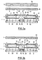
- the format plate 2 lies on the intermediate plate 7 of the basic tool 1.
- the correct arrangement of the format plate 2 on the base tool 1 is ensured via the guide bolts 17 which engage in the guide openings 16 of the format plate 2.
- the pressure plate 3 resting on the stamp 13 of the basic tool 1 is inserted into the recess 18 of the format plate 2 in such a way that the pressure plate 3 is flush with the format plate 2.
- the Buggplatte 4 held on the mounting plate 5 is at some distance above the basic tool 1 and the format plate 2, so that the blank 26 can be placed on the pressure plate 3.
- the correct arrangement of the blank 26 is ensured by the contact strips 19, between which the blank 26 is arranged.
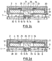
- FIGS. 2 b to 2 d the mounting plate 5 and the bugg plate 4 to be attached to this are shown at a distance from each other. Since only the bugg plate is decisive for the bowing process in the upper tool, an additional representation of the fastening plate 5 has been omitted in FIGS. 2 b to 2 d.
- a vacuum generated by a vacuum pump is applied to the by the format plate 2 and the pressure plate 3 tightly closed recess 10 applied in the intermediate plate 7. Since the stamp 13 is arranged so as to be vertically displaceable against the force of the springs 15, the pressure plate 3 resting on the stamp 13 is pulled downward through the recess 18 in the format plate by the underpressure generated in the recess 10. By means of stop strips 29, on which the stamp 13 is placed, it is determined how far the pressure plate 3 is drawn into the recess 18 in the format plate 2.
- the push plate 4 is now placed on the format plate 2, the push plate 4 also being guided through the guide bolts 17 of the basic tool 1. Due to the bevelled or radiused edge edges 22 of the recess 21, the edge portions 25 of the blank 26 projecting beyond the format plate 2 are bent inwards.
- the format plate 2 By further pressing down the bugg plate 4 and thus the format plate 2 lying against it and the intermediate plate 7 of the basic tool 1 against the force of the springs 8, the format plate 2 becomes on the pressure plate held on the stamp 13 3 pressed downwards, the bent edge portions 25 of the blank 26 being pressed onto the base surface 27 of the blank 26.
- the displacement of the format plate 2 with respect to the pressure plate 3 is limited by spacer strips 30 on which the intermediate plate 7 comes to rest.
- the displacement path of the format plate 2 can be varied by changing the spacer strips 30.
- the bugg plate 4 after the bugg plate 4 has been placed on the format plate 2, the bugg plate 4 is not pressed further down, but instead the plunger 13 with the pressure plate 3 is pressed hydraulically upward, for example, so that the pressure plate 3 passes through the recess 18 of the format plate 2 and rests against the bow plate 4 in the region of the depression 21. As a result, the bent-over edge sections 25 of the blank 26 are also pressed onto the base surface 27 of the blank 26.
- the bugg plate and / or the pressure plate 3 can be heated.
- a frame 28 with an appropriately adapted size can be inserted into the recess 10 of the intermediate plate 7 of the basic tool, so that the volume to be evacuated is kept as low as possible.
- the parts of the folding device which have to be adapted to the workpiece to be machined that is to say the format plate 2, the pressure plate 3 and the bending plate 4, are easily replaceable by the Format plate 2 are removed from the guide bolts 17 of the basic tool 1 and the pressure plate 3 from the stamp 13 and the bugg plate 4 is released from the fastening plate 5 by unlocking the quick-release fastener or switching off the magnet 24.
- the production of the plates 2, 3, 4 to be exchanged is relatively simple, since only small millings have to be made in the bugg plate 4, while in the format plate 2 only the dimension of the recess 18 and the arrangement of the contact strips 19 need to be changed.
- the pressure plate 3 also only has to be adapted to the desired surface of the molded part and can then simply be placed on the punch 13 of the basic tool 1.
Landscapes
- Engineering & Computer Science (AREA)
- Mechanical Engineering (AREA)
- Chemical & Material Sciences (AREA)
- Organic Chemistry (AREA)
- Shaping Of Tube Ends By Bending Or Straightening (AREA)
- Making Paper Articles (AREA)
- Manufacture Or Reproduction Of Printing Formes (AREA)
- Blow-Moulding Or Thermoforming Of Plastics Or The Like (AREA)
Applications Claiming Priority (3)
| Application Number | Priority Date | Filing Date | Title |
|---|---|---|---|
| DE4411500 | 1994-04-05 | ||
| DE4411500A DE4411500C2 (de) | 1994-04-05 | 1994-04-05 | Verfahren und Vorrichtung zum Einschlagen oder Buggen |
| US08/415,813 US5593700A (en) | 1994-04-05 | 1995-04-03 | Folding apparatus and folding method |
Publications (3)
| Publication Number | Publication Date |
|---|---|
| EP0676477A2 true EP0676477A2 (fr) | 1995-10-11 |
| EP0676477A3 EP0676477A3 (fr) | 1997-01-08 |
| EP0676477B1 EP0676477B1 (fr) | 2001-08-29 |
Family
ID=25935324
Family Applications (1)
| Application Number | Title | Priority Date | Filing Date |
|---|---|---|---|
| EP95105093A Expired - Lifetime EP0676477B1 (fr) | 1994-04-05 | 1995-04-05 | Procédé et dispositif pour rabattre ou plier |
Country Status (3)
| Country | Link |
|---|---|
| US (1) | US5593700A (fr) |
| EP (1) | EP0676477B1 (fr) |
| DE (1) | DE4411500C2 (fr) |
Cited By (2)
| Publication number | Priority date | Publication date | Assignee | Title |
|---|---|---|---|---|
| EP1531036A1 (fr) * | 2003-11-11 | 2005-05-18 | Karl-Heinz Hübner | Procédé et dispositif pour envelopper des matériaux flexibles |
| IT201800002439A1 (it) * | 2018-02-06 | 2018-05-06 | Fustellificio Toscano S A S Di Ugo Naldini & C | Dispositivo e metodo per l'assemblaggio di portafogli |
Families Citing this family (15)
| Publication number | Priority date | Publication date | Assignee | Title |
|---|---|---|---|---|
| US6298896B1 (en) * | 2000-03-28 | 2001-10-09 | Northrop Grumman Corporation | Apparatus for constructing a composite structure |
| US6592351B2 (en) | 2001-01-22 | 2003-07-15 | Crane Plastics Company Llc | Turret loading device for extrusion line |
| NL1023365C2 (nl) * | 2003-05-08 | 2004-11-09 | Fountain Patents B V | Werkwijze en inrichting voor het vervaardigen van voertuigonderdelen. |
| US20070063386A1 (en) * | 2005-09-01 | 2007-03-22 | Seaver Richard T | Mold tool having movable core |
| US9149990B2 (en) * | 2007-03-30 | 2015-10-06 | Airbus Operations Gmbh | Apparatus for the forming of a lay-up of fibre composite material |
| WO2011151374A1 (fr) * | 2010-06-03 | 2011-12-08 | Cryovac, Inc. | Plaque et appareil permettant de former un article creux à rebord en matière plastique |
| KR20140022386A (ko) | 2011-04-18 | 2014-02-24 | 파이프 컴파니, 엘.엘.씨. | 기존 파이프의 보호 및 강화용 팽창성 라이너 |
| FR2987628B1 (fr) * | 2012-03-01 | 2014-02-28 | Vuitton Louis Sa | Machine a remborder et son utilisation, procede de rembordage, levier de rembordage, ensemble d'un levier de rembordage et d'un corps de rembordage, kit de rembordage et support de rembordage |
| AU2015275790A1 (en) | 2014-06-16 | 2016-12-01 | Fyfe Co. Llc | Repair of pipes |
| CA2897301C (fr) | 2014-07-14 | 2020-06-02 | Fyfe Co. Llc | Revetement de tuyau etanche et tres resistant |
| US9993992B2 (en) | 2015-04-17 | 2018-06-12 | Fyfe Co. Llc | Structural fabric useful for lining pipe |
| ITUB20153493A1 (it) * | 2015-09-09 | 2017-03-09 | Gruppo Mecc Luciani S R L | Attrezzatura per l'applicazione di borchie. |
| US10077855B2 (en) | 2015-09-22 | 2018-09-18 | Ina Acquisition Corp. | Method of lining pipe with high strength liner, high strength liner, and pipe lined with high strength liner |
| US11173634B2 (en) | 2018-02-01 | 2021-11-16 | Ina Acquisition Corp | Electromagnetic radiation curable pipe liner and method of making and installing the same |
| US10704728B2 (en) | 2018-03-20 | 2020-07-07 | Ina Acquisition Corp. | Pipe liner and method of making same |
Family Cites Families (16)
| Publication number | Priority date | Publication date | Assignee | Title |
|---|---|---|---|---|
| US1640918A (en) * | 1924-05-27 | 1927-08-30 | Samuel Ward Mfg Company | Bookbinding machine |
| US1640903A (en) * | 1924-06-10 | 1927-08-30 | Samuel Ward Mfg Company | Covering machine |
| US1946999A (en) * | 1933-06-27 | 1934-02-13 | Maurice M Balsam | Machine for turning the edges of flexible material |
| US3073141A (en) * | 1960-06-23 | 1963-01-15 | Freeman Co Louis G | Apparatus for folding leather pieces and the like |
| DE1239056B (de) * | 1962-10-30 | 1967-04-20 | Biedermann K G Geb | Verfahren zum Umbuggen von Leder, Kunststoffen, Textilien und aehnlichen flexiblen Werkstoffen |
| US3459014A (en) * | 1968-03-18 | 1969-08-05 | Freeman Co Louis G | Folding die guide means |
| US3640668A (en) * | 1969-07-24 | 1972-02-08 | Packaging Ind Inc | Reentrant forming apparatus |
| SE7706109L (sv) * | 1976-12-10 | 1978-06-11 | Multivac Haggenmueller Kg | Sett och anordning for formning av plastfolier |
| US4106396A (en) * | 1977-05-18 | 1978-08-15 | Phillips Petroleum Company | Apparatus for forming a container having a rolled rim |
| US4263688A (en) * | 1979-03-21 | 1981-04-28 | Louis G. Freeman Company | Top and bottom die assemblies for folding the edges of a non-rigid workpiece |
| US4534725A (en) * | 1982-04-01 | 1985-08-13 | International Paper Company | Apparatus for manufacturing ovenable paperboard articles |
| CA1211610A (fr) * | 1983-12-23 | 1986-09-23 | Hugh Van Melle | Bague d'espacement segmentee |
| JPS60178020A (ja) * | 1984-02-24 | 1985-09-12 | Katashi Aoki | 薄肉容器の成形方法及び金型装置 |
| US4897030A (en) * | 1987-01-08 | 1990-01-30 | Slm Manufacturing Corporation | Apparatus for lengthwise folding thermoplastic strip material |
| DE9213007U1 (de) * | 1992-09-26 | 1993-01-14 | Traut, Horst, 6570 Kirn | Vakuum-Umbugwerkzeug |
| DE9405666U1 (de) * | 1994-04-06 | 1994-06-01 | Traut, Horst, 55606 Kirn | Basis-Umbugwerkzeug mit pneumatic Druckpaket und auswechselbaren Teilen |
-
1994
- 1994-04-05 DE DE4411500A patent/DE4411500C2/de not_active Expired - Fee Related
-
1995
- 1995-04-03 US US08/415,813 patent/US5593700A/en not_active Expired - Fee Related
- 1995-04-05 EP EP95105093A patent/EP0676477B1/fr not_active Expired - Lifetime
Cited By (2)
| Publication number | Priority date | Publication date | Assignee | Title |
|---|---|---|---|---|
| EP1531036A1 (fr) * | 2003-11-11 | 2005-05-18 | Karl-Heinz Hübner | Procédé et dispositif pour envelopper des matériaux flexibles |
| IT201800002439A1 (it) * | 2018-02-06 | 2018-05-06 | Fustellificio Toscano S A S Di Ugo Naldini & C | Dispositivo e metodo per l'assemblaggio di portafogli |
Also Published As
| Publication number | Publication date |
|---|---|
| US5593700A (en) | 1997-01-14 |
| EP0676477A3 (fr) | 1997-01-08 |
| DE4411500A1 (de) | 1995-11-02 |
| EP0676477B1 (fr) | 2001-08-29 |
| DE4411500C2 (de) | 1999-02-11 |
Similar Documents
| Publication | Publication Date | Title |
|---|---|---|
| EP0676477B1 (fr) | Procédé et dispositif pour rabattre ou plier | |
| DE69321728T2 (de) | Zweistufiger matritzensatz | |
| EP2303488B1 (fr) | Procédé et dispositif pour la production de pièces découpées de précision à partir d'une bande de matériau | |
| DE2932698C2 (de) | Vorrichtung zum Zusammenlegen von Trägermatten und Metallfolienbahnabschnitten im Zuge der Herstellung von Laminatplatten | |
| DE2925500A1 (de) | Verfahren und vorrichtung zur herstellung von kaschierten formteilen | |
| DE2312362A1 (de) | Verfahren und vorrichtung zum verschweissen und entgraten von kunststoffprofilen | |
| DE102008060073A1 (de) | Rillung von Umschlägen in einem Klebebinder | |
| DE2911831C2 (de) | Vorrichtung zum Herstellen von Abstandshalterahmen für Isolierglasscheiben | |
| DE102010018534A1 (de) | Vorrichtung zum Formen eines Werkstücks | |
| DE3411023C2 (de) | Vorrichtung zum Herstellen und/oder Bearbeiten von kaschierten Werkstücken | |
| DE4400388C2 (de) | Verfahren und Vorrichtung zum Herstellen eines Formteils aus mindestens einer Trägerschicht und einer Kaschierschicht | |
| DE202010014913U1 (de) | Vorrichtung zum Bearbeiten, insbesondere zum Stanzen und Verbinden, eines Werkstücks | |
| EP0127035A2 (fr) | Procédé de fixation sûre des bords d'une feuille de recouvrement appliquée sur un substrat plan et appareil de formage pour la mise en oeuvre du procédé | |
| DE2427246A1 (de) | Vorrichtung zur herstellung eines aus einem rohteil und einem angeformten spritzgussteil zusammengesetzten gegenstandes | |
| DE29905738U1 (de) | Stanzvorrichtung | |
| DE9115347U1 (de) | Vertikale Stanzvorrichtung | |
| DE308801C (fr) | ||
| DE3127227C2 (de) | Ziehwerkzeug | |
| DE456599C (de) | Verfahren und Vorrichtung zur Herstellung von Schachteln, wobei die Verbindung der Schachtelecken durch Klebestreifen hergestellt wird | |
| DE3318901A1 (de) | Verfahren zur sicheren befestigung einer auf einer aussenflaeche eines flaechigen formlings aufgebrachten auflage im bereich der flaechenraender und formwerkzeug hierzu | |
| DE2801998A1 (de) | Stanzpresse mit werkzeugaufnahme | |
| DE19627387A1 (de) | Vorrichtung zum Hinterform-Pressen eines mit einer Dekorfolie zu versehenden Kunststoff-Trägerteiles | |
| DE2546126C3 (de) | Werkzeug zum Stanzen und/oder Prägen von Papier, Karton, Kunststoff o.dgl | |
| DE19910471A1 (de) | Stanzwerkzeug zum Ausstanzen von Ausweiskarten, Bankkarten o. dgl. aus einem Kartennutzen bestehend aus Kunststoff | |
| EP1935527B1 (fr) | Procédé et système destinés à la fabrication de pièces de déformage géométriquement variables à partir de matériau en bande |
Legal Events
| Date | Code | Title | Description |
|---|---|---|---|
| PUAI | Public reference made under article 153(3) epc to a published international application that has entered the european phase |
Free format text: ORIGINAL CODE: 0009012 |
|
| AK | Designated contracting states |
Kind code of ref document: A2 Designated state(s): DE FR GB IT |
|
| PUAL | Search report despatched |
Free format text: ORIGINAL CODE: 0009013 |
|
| AK | Designated contracting states |
Kind code of ref document: A3 Designated state(s): DE FR GB IT |
|
| 16A | New documents despatched to applicant after publication of the search report | ||
| 17P | Request for examination filed |
Effective date: 19970708 |
|
| 17Q | First examination report despatched |
Effective date: 19991004 |
|
| GRAG | Despatch of communication of intention to grant |
Free format text: ORIGINAL CODE: EPIDOS AGRA |
|
| GRAG | Despatch of communication of intention to grant |
Free format text: ORIGINAL CODE: EPIDOS AGRA |
|
| GRAH | Despatch of communication of intention to grant a patent |
Free format text: ORIGINAL CODE: EPIDOS IGRA |
|
| GRAH | Despatch of communication of intention to grant a patent |
Free format text: ORIGINAL CODE: EPIDOS IGRA |
|
| GRAA | (expected) grant |
Free format text: ORIGINAL CODE: 0009210 |
|
| AK | Designated contracting states |
Kind code of ref document: B1 Designated state(s): DE FR GB IT |
|
| REF | Corresponds to: |
Ref document number: 59509544 Country of ref document: DE Date of ref document: 20011004 |
|
| REG | Reference to a national code |
Ref country code: GB Ref legal event code: IF02 |
|
| GBT | Gb: translation of ep patent filed (gb section 77(6)(a)/1977) |
Effective date: 20011130 |
|
| EN | Fr: translation not filed | ||
| PLBE | No opposition filed within time limit |
Free format text: ORIGINAL CODE: 0009261 |
|
| STAA | Information on the status of an ep patent application or granted ep patent |
Free format text: STATUS: NO OPPOSITION FILED WITHIN TIME LIMIT |
|
| 26N | No opposition filed | ||
| ET | Fr: translation filed | ||
| REG | Reference to a national code |
Ref country code: FR Ref legal event code: ERR Free format text: BOPI DE PUBLICATION N: 02/04 PAGES: 241 PARTIE DU BULLETIN CONCERNEE: BREVETS EUROPEENS DONT LA TRADUCTION N'A PAS ETE REMISE A I'INPI IL Y A LIEU DE SUPPRIMER: LA MENTION DE LA NON REMISE. LA REMISE DE LA TRADUCTION EST PUBLIEE DANS LE PRESENT BOPI. |
|
| PGFP | Annual fee paid to national office [announced via postgrant information from national office to epo] |
Ref country code: GB Payment date: 20100324 Year of fee payment: 16 |
|
| GBPC | Gb: european patent ceased through non-payment of renewal fee |
Effective date: 20110405 |
|
| PG25 | Lapsed in a contracting state [announced via postgrant information from national office to epo] |
Ref country code: GB Free format text: LAPSE BECAUSE OF NON-PAYMENT OF DUE FEES Effective date: 20110405 |
|
| PGFP | Annual fee paid to national office [announced via postgrant information from national office to epo] |
Ref country code: DE Payment date: 20130625 Year of fee payment: 19 |
|
| PGFP | Annual fee paid to national office [announced via postgrant information from national office to epo] |
Ref country code: IT Payment date: 20130424 Year of fee payment: 19 Ref country code: FR Payment date: 20130523 Year of fee payment: 19 |
|
| REG | Reference to a national code |
Ref country code: DE Ref legal event code: R119 Ref document number: 59509544 Country of ref document: DE |
|
| REG | Reference to a national code |
Ref country code: FR Ref legal event code: ST Effective date: 20141231 |
|
| REG | Reference to a national code |
Ref country code: DE Ref legal event code: R119 Ref document number: 59509544 Country of ref document: DE Effective date: 20141101 |
|
| PG25 | Lapsed in a contracting state [announced via postgrant information from national office to epo] |
Ref country code: DE Free format text: LAPSE BECAUSE OF NON-PAYMENT OF DUE FEES Effective date: 20141101 |
|
| PG25 | Lapsed in a contracting state [announced via postgrant information from national office to epo] |
Ref country code: FR Free format text: LAPSE BECAUSE OF NON-PAYMENT OF DUE FEES Effective date: 20140430 |
|
| PG25 | Lapsed in a contracting state [announced via postgrant information from national office to epo] |
Ref country code: IT Free format text: LAPSE BECAUSE OF NON-PAYMENT OF DUE FEES Effective date: 20140405 |