EP0676571A1 - Bouclier pour une vanne papillon - Google Patents
Bouclier pour une vanne papillon Download PDFInfo
- Publication number
- EP0676571A1 EP0676571A1 EP95105218A EP95105218A EP0676571A1 EP 0676571 A1 EP0676571 A1 EP 0676571A1 EP 95105218 A EP95105218 A EP 95105218A EP 95105218 A EP95105218 A EP 95105218A EP 0676571 A1 EP0676571 A1 EP 0676571A1
- Authority
- EP
- European Patent Office
- Prior art keywords
- protective shield
- butterfly valve
- valve according
- disc
- valve disc
- Prior art date
- Legal status (The legal status is an assumption and is not a legal conclusion. Google has not performed a legal analysis and makes no representation as to the accuracy of the status listed.)
- Withdrawn
Links
- 238000007789 sealing Methods 0.000 claims abstract description 20
- 238000011144 upstream manufacturing Methods 0.000 claims abstract description 17
- 230000001681 protective effect Effects 0.000 claims description 39
- 239000000463 material Substances 0.000 claims description 6
- 239000011248 coating agent Substances 0.000 claims description 4
- 238000000576 coating method Methods 0.000 claims description 4
- 239000007788 liquid Substances 0.000 claims description 4
- 239000002320 enamel (paints) Substances 0.000 claims description 2
- 239000002245 particle Substances 0.000 description 5
- 230000002349 favourable effect Effects 0.000 description 3
- 230000001771 impaired effect Effects 0.000 description 2
- 238000005299 abrasion Methods 0.000 description 1
- 238000010276 construction Methods 0.000 description 1
- 210000003298 dental enamel Anatomy 0.000 description 1
- 230000000694 effects Effects 0.000 description 1
- 238000004519 manufacturing process Methods 0.000 description 1
- 239000002184 metal Substances 0.000 description 1
- 239000007769 metal material Substances 0.000 description 1
- 239000007787 solid Substances 0.000 description 1
- 239000000126 substance Substances 0.000 description 1
Images
Classifications
-
- F—MECHANICAL ENGINEERING; LIGHTING; HEATING; WEAPONS; BLASTING
- F16—ENGINEERING ELEMENTS AND UNITS; GENERAL MEASURES FOR PRODUCING AND MAINTAINING EFFECTIVE FUNCTIONING OF MACHINES OR INSTALLATIONS; THERMAL INSULATION IN GENERAL
- F16K—VALVES; TAPS; COCKS; ACTUATING-FLOATS; DEVICES FOR VENTING OR AERATING
- F16K27/00—Construction of housing; Use of materials therefor
- F16K27/02—Construction of housing; Use of materials therefor of lift valves
- F16K27/0209—Check valves or pivoted valves
- F16K27/0218—Butterfly valves
Definitions
- the invention relates to a butterfly valve as a fitting for liquid or gaseous media, with a fitting housing, a media passage opening in the fitting housing and a flap disc arranged in the passage opening and pivotably mounted on the fitting housing about an axis of rotation, which has a circumferential sealing surface and between a closed position, in which it seals the passage opening and can be pivoted to an open position.
- Such butterfly valves are state of the art. They are often used in particular with larger nominal widths instead of the ball valves that can be used alternatively, after they are cheaper than ball valves.
- ball valves are used in most cases to shut off liquid or gaseous media containing abrasive particles.
- these ball valves are modified in their individual parts to withstand the abrasive conditions; For example, hard material coating is applied to the balls and the ball seals are made from partially metallic materials.
- Ball valves modified in this way are very high in the purchase price, depending on the equipment, and still have to be repaired or replaced due to the unavoidable wear.
- Another disadvantage of ball valves is that they often have dead spaces in which abrasive substances can accumulate, so that the function of the ball valve is impaired.
- butterfly valves have the advantage over ball valves that they have no or very little dead space and the problem mentioned above therefore practically does not occur.
- the use of butterfly valves should be avoided, since when the butterfly valve is open, the sealing surface of the valve disc facing the media flow is fully exposed to abrasion and, after some operating time, the sealing function of the valve disc in the closed position is impaired by damage to the sealing surface.
- the invention has for its object to develop the butterfly valve of the type mentioned so that the problem of sealing surface damage to the valve disc is reduced or eliminated when using abrasive media.
- an elongated protective shield is arranged in the through opening outside the range of movement of the valve disc, which extends generally in the direction parallel to the axis of rotation and at least in the open position of the valve disc in the flow direction of the medium, the upstream sealing surface of the Valve disc is upstream.
- An additional protective shield is therefore proposed according to the invention, which shields the sealing surface of the valve disc against inflowing solid particles when the valve is open, in particular fully opened.
- the protective shield is expediently rigidly fixed relative to the valve housing, so that it shields the sealing surface of the valve disc in a very specific opening position, usually in the opening position in which the valve disc is aligned parallel to the general flow direction of the medium.
- the protective shield can be screwed or welded to the valve housing, or it can alternatively be attached to a connection flange or the like to be attached to the valve housing, or it can be clamped between the valve housing and the connection flange.
- the construction of the protective shield is such that the downstream side of the protective shield is essentially curved in a circular arc in the plane of its longitudinal extent, the radius of curvature of the downstream side essentially corresponding to the radius of the valve disc;
- the downstream side of the protective shield lies opposite the sealing surface of the valve disc in its open position at a very small distance, only the manufacturing and assembly tolerances being observed in order to reliably preclude the protective shield from obstructing the movement of the valve disc. This optimally protects the sealing surface of the valve disc.
- the upstream side of the protective shield is expediently also generally curved in the shape of a circular arc in the plane of its longitudinal extent, so that the protective shield as a whole can take the form of a narrow circular ring segment.
- the width of the protective shield measured transversely to the direction of flow, is expediently at least equal to the thickness of the valve disc, but is preferably slightly larger, in order to ensure optimal protection of the edge regions of the sealing surfaces as well.
- the protective shield which will generally consist essentially of a suitable metal, can be provided, at least on its upstream side, with a hard material coating, in particular with an enamel coating, around the side of the surface exposed to the abrasive particles Protective shield in addition to protect.
- the type of hard material covering can be selected according to the medium to be used.
- the protective shield on its upstream side has a cross-section which is curved in the plane perpendicular to its longitudinal extension and which is aerodynamically or fluidically optimized. In this way it can be achieved that, due to the aerodynamically favorable shape of the protective shield, the media flow flows past the open flap in a laminar manner.
- This further advantage of the protective shield according to the invention has an effect, in particular, in butterfly valves with eccentrically or double-eccentrically mounted butterfly valves, which, compared to butterfly valves with centrally mounted butterfly valves, have much thicker butterfly valves with much wider sealing surfaces which, for design reasons, cannot be designed with a favorable flow.
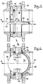
- the reference number 10 denotes a fitting housing which comprises two coaxial housing parts 12, 14 which are screwed together.
- the valve body has a cylindrical through opening 18 for liquid or gaseous media.
- a valve disc 32 is pivotally mounted in the valve housing 10 via shafts 28, 30, of which the shaft 28 can be driven.
- the valve disc is shown in its open position, in which it is parallel to the axis 34 of the through opening 18 of the valve body 10; in Figure 1, the closed position of the valve disc 32 is also shown in dash-dotted lines, in which the valve disc is oriented perpendicular to the axis 34 and bears sealingly via its sealing surface 36 which extends circumferentially on the end face against a seal 16 which is held between the housing parts 12 and 14 .
- the valve disc 32 is mounted in the valve body in such a double-eccentric manner that the valve disc lifts off the seal 16 at the start of the opening movement, which results in less seat wear and the required torque is reduced.
- the butterfly valve described above with double eccentrically mounted valve disc is state of the art.
- a protective shield designated overall by reference numeral 38, is arranged in front of the valve disc 32 in the passage opening defined by the valve housing or the pipe system connected thereto, outside the range of movement of the valve disc 32 and in the general direction of flow of the medium, which is identified by the arrow A.
- the protective shield 38 has a circular segment shape in the side view according to FIG on. With its downstream side 40, it lies opposite the upstream sealing surface 36 of the valve disc 32 in the illustrated, open position of the valve disc 32, forming an only narrow gap of the order of magnitude of 0.5-5 mm.
- the thickness of the protective shield 38 measured transversely to the axis 34 is somewhat larger than the thickness of the flap disc 32, for example 5% to 50% thicker.
- the curved, elongated protective shield 38 extends in its longitudinal direction essentially parallel to the axis of rotation 42 of the valve disc 32 or, in other words, the main plane of the protective shield 38 coincides with the main plane of the valve disc 32 in the open position.
- the upstream side 44 of the protective shield 38 is curved approximately parabolically; in particular, this curvature is to be designed in such a way that it is aerodynamically or fluidically favorable or optimal, whereby the aim is to ensure that the medium flows past the open disc 32 in a laminar manner.
- the upstream side 44 of the protective shield can be covered with a hard material covering, e.g. Enamel coated to have a particularly high wear resistance against abrasive particles in the media flow.
- a hard material covering e.g. Enamel coated to have a particularly high wear resistance against abrasive particles in the media flow.
- the protective shield 38 can be fastened in any suitable manner to the fitting housing 10 or the connecting flange 24 located upstream thereof, for example, be screwed or welded on, or it can, as in the case of the exemplary embodiment shown, be clamped between the fitting housing 10 and the connecting flange 24.
- radially extending projections 46, 48 are formed at the two ends of the protective shield 38, which can be inserted into correspondingly shaped recesses 50, 52 on the connecting flange 24 and are held therein in their desired position.
- the protective shield 38 reliably protects the upstream sealing surface 36 of the valve disc 32 against the impact of abrasive particles in the media flow and thus decisively extends the service life of the butterfly valve.
Landscapes
- Engineering & Computer Science (AREA)
- General Engineering & Computer Science (AREA)
- Mechanical Engineering (AREA)
- Lift Valve (AREA)
- Details Of Valves (AREA)
Applications Claiming Priority (2)
| Application Number | Priority Date | Filing Date | Title |
|---|---|---|---|
| DE9405727U DE9405727U1 (de) | 1994-04-06 | 1994-04-06 | Schutzschild für Absperrklappe |
| DE9405727U | 1994-04-06 |
Publications (1)
| Publication Number | Publication Date |
|---|---|
| EP0676571A1 true EP0676571A1 (fr) | 1995-10-11 |
Family
ID=6906987
Family Applications (1)
| Application Number | Title | Priority Date | Filing Date |
|---|---|---|---|
| EP95105218A Withdrawn EP0676571A1 (fr) | 1994-04-06 | 1995-04-06 | Bouclier pour une vanne papillon |
Country Status (2)
| Country | Link |
|---|---|
| EP (1) | EP0676571A1 (fr) |
| DE (1) | DE9405727U1 (fr) |
Citations (5)
| Publication number | Priority date | Publication date | Assignee | Title |
|---|---|---|---|---|
| US1824168A (en) * | 1929-02-18 | 1931-09-22 | Pelton Water Wheel Co | Butterfly valve |
| CH345774A (fr) * | 1957-07-04 | 1960-04-15 | Bouchayer & Viallet Ets | Vanne-papillon |
| JPS5794170A (en) * | 1981-10-19 | 1982-06-11 | Babcock Hitachi Kk | Damper having protecting cover |
| DE3148521A1 (de) * | 1980-12-15 | 1982-06-24 | Mitsui Coke Co. Ltd., Tokyo | "druckreduzierventil fuer kohleverfluessigungs- und -vergasungsanlagen" |
| JPS60139980A (ja) * | 1983-12-28 | 1985-07-24 | Maezawa Kogyo Kk | 弁 |
-
1994
- 1994-04-06 DE DE9405727U patent/DE9405727U1/de not_active Expired - Lifetime
-
1995
- 1995-04-06 EP EP95105218A patent/EP0676571A1/fr not_active Withdrawn
Patent Citations (5)
| Publication number | Priority date | Publication date | Assignee | Title |
|---|---|---|---|---|
| US1824168A (en) * | 1929-02-18 | 1931-09-22 | Pelton Water Wheel Co | Butterfly valve |
| CH345774A (fr) * | 1957-07-04 | 1960-04-15 | Bouchayer & Viallet Ets | Vanne-papillon |
| DE3148521A1 (de) * | 1980-12-15 | 1982-06-24 | Mitsui Coke Co. Ltd., Tokyo | "druckreduzierventil fuer kohleverfluessigungs- und -vergasungsanlagen" |
| JPS5794170A (en) * | 1981-10-19 | 1982-06-11 | Babcock Hitachi Kk | Damper having protecting cover |
| JPS60139980A (ja) * | 1983-12-28 | 1985-07-24 | Maezawa Kogyo Kk | 弁 |
Non-Patent Citations (3)
| Title |
|---|
| LANGLEY RESEARCH CENTER: "Aerodynamic shutoff valve", NTIS TECH NOTES, vol. 1992, no. 2301, 1992, SPRINGFIELD US, pages 439, XP000304408 * |
| PATENT ABSTRACTS OF JAPAN vol. 6, no. 187 (M - 158)<1065> 25 September 1982 (1982-09-25) * |
| PATENT ABSTRACTS OF JAPAN vol. 9, no. 303 (M - 434)<2026> 30 November 1985 (1985-11-30) * |
Also Published As
| Publication number | Publication date |
|---|---|
| DE9405727U1 (de) | 1994-06-16 |
Similar Documents
| Publication | Publication Date | Title |
|---|---|---|
| EP1771653B1 (fr) | Soupape destinee a etre utilisee dans une canalisation de carburant d'un vehicule automobile | |
| EP1891302B1 (fr) | Systeme de plaques pour turbocompresseur | |
| DE3632858C2 (fr) | ||
| EP1493951B1 (fr) | Vanne papillon | |
| EP0507127B1 (fr) | Distributeur à tube | |
| DE2457230B2 (de) | Hahn zum Absperren und Steuern von Hochtemperatur-Strömungsmedien | |
| EP2345831B1 (fr) | Elément de blocage | |
| DE3142808A1 (de) | "gegen unbefugten eingriff gesicherter gaszaehler" | |
| DE102013107580A1 (de) | Diagonal-Ventilator | |
| DE2849281C2 (fr) | ||
| DE102004043644A1 (de) | Fluidventilanordnung | |
| EP0609660A1 (fr) | Clapet à fermeture rapide | |
| EP2816264B1 (fr) | Robinetterie d'arrêt ou de régulation d'un fluide | |
| DE4426471A1 (de) | Drehabsperrorgan | |
| EP0637364B1 (fr) | Etoupage de l'axe de clapets d'arret | |
| DE9405727U1 (de) | Schutzschild für Absperrklappe | |
| EP1092899B1 (fr) | Dispositif d'étanchéité | |
| DE3546086C2 (fr) | ||
| EP0318737B1 (fr) | Robinet à boisseau sphérique | |
| DE8802186U1 (de) | Absperrarmatur | |
| DE4420461C2 (de) | Rohrkrümmer | |
| DE19530224B4 (de) | Dichtungsanordnung für eine Absperrklappe oder eine Regelklappe | |
| DE9312095U1 (de) | Absperreinrichtung für eine gasführende Leitung | |
| DE10147737A1 (de) | Monoblockschieber mit gummierter Platte | |
| DE102017129666B4 (de) | Absperrklappe |
Legal Events
| Date | Code | Title | Description |
|---|---|---|---|
| PUAI | Public reference made under article 153(3) epc to a published international application that has entered the european phase |
Free format text: ORIGINAL CODE: 0009012 |
|
| AK | Designated contracting states |
Kind code of ref document: A1 Designated state(s): AT BE CH DE FR LI LU NL |
|
| 17P | Request for examination filed |
Effective date: 19960409 |
|
| STAA | Information on the status of an ep patent application or granted ep patent |
Free format text: STATUS: THE APPLICATION HAS BEEN WITHDRAWN |
|
| 18W | Application withdrawn |
Withdrawal date: 19970129 |