EP0676573A1 - Wegeventil in Grundplattenausführung - Google Patents
Wegeventil in Grundplattenausführung Download PDFInfo
- Publication number
- EP0676573A1 EP0676573A1 EP95250027A EP95250027A EP0676573A1 EP 0676573 A1 EP0676573 A1 EP 0676573A1 EP 95250027 A EP95250027 A EP 95250027A EP 95250027 A EP95250027 A EP 95250027A EP 0676573 A1 EP0676573 A1 EP 0676573A1
- Authority
- EP
- European Patent Office
- Prior art keywords
- base plate
- valve body
- opening
- pressure medium
- plate element
- Prior art date
- Legal status (The legal status is an assumption and is not a legal conclusion. Google has not performed a legal analysis and makes no representation as to the accuracy of the status listed.)
- Granted
Links
Images

Classifications
-
- F—MECHANICAL ENGINEERING; LIGHTING; HEATING; WEAPONS; BLASTING
- F15—FLUID-PRESSURE ACTUATORS; HYDRAULICS OR PNEUMATICS IN GENERAL
- F15B—SYSTEMS ACTING BY MEANS OF FLUIDS IN GENERAL; FLUID-PRESSURE ACTUATORS, e.g. SERVOMOTORS; DETAILS OF FLUID-PRESSURE SYSTEMS, NOT OTHERWISE PROVIDED FOR
- F15B13/00—Details of servomotor systems ; Valves for servomotor systems
- F15B13/02—Fluid distribution or supply devices characterised by their adaptation to the control of servomotors
- F15B13/06—Fluid distribution or supply devices characterised by their adaptation to the control of servomotors for use with two or more servomotors
- F15B13/08—Assemblies of units, each for the control of a single servomotor only
- F15B13/0803—Modular units
- F15B13/0821—Attachment or sealing of modular units to each other
-
- F—MECHANICAL ENGINEERING; LIGHTING; HEATING; WEAPONS; BLASTING
- F15—FLUID-PRESSURE ACTUATORS; HYDRAULICS OR PNEUMATICS IN GENERAL
- F15B—SYSTEMS ACTING BY MEANS OF FLUIDS IN GENERAL; FLUID-PRESSURE ACTUATORS, e.g. SERVOMOTORS; DETAILS OF FLUID-PRESSURE SYSTEMS, NOT OTHERWISE PROVIDED FOR
- F15B13/00—Details of servomotor systems ; Valves for servomotor systems
- F15B13/02—Fluid distribution or supply devices characterised by their adaptation to the control of servomotors
- F15B13/04—Fluid distribution or supply devices characterised by their adaptation to the control of servomotors for use with a single servomotor
- F15B13/0401—Valve members; Fluid interconnections therefor
- F15B13/0402—Valve members; Fluid interconnections therefor for linearly sliding valves, e.g. spool valves
-
- F—MECHANICAL ENGINEERING; LIGHTING; HEATING; WEAPONS; BLASTING
- F15—FLUID-PRESSURE ACTUATORS; HYDRAULICS OR PNEUMATICS IN GENERAL
- F15B—SYSTEMS ACTING BY MEANS OF FLUIDS IN GENERAL; FLUID-PRESSURE ACTUATORS, e.g. SERVOMOTORS; DETAILS OF FLUID-PRESSURE SYSTEMS, NOT OTHERWISE PROVIDED FOR
- F15B13/00—Details of servomotor systems ; Valves for servomotor systems
- F15B13/02—Fluid distribution or supply devices characterised by their adaptation to the control of servomotors
- F15B13/06—Fluid distribution or supply devices characterised by their adaptation to the control of servomotors for use with two or more servomotors
- F15B13/08—Assemblies of units, each for the control of a single servomotor only
- F15B13/0803—Modular units
- F15B13/0807—Manifolds
- F15B13/0817—Multiblock manifolds
-
- F—MECHANICAL ENGINEERING; LIGHTING; HEATING; WEAPONS; BLASTING
- F15—FLUID-PRESSURE ACTUATORS; HYDRAULICS OR PNEUMATICS IN GENERAL
- F15B—SYSTEMS ACTING BY MEANS OF FLUIDS IN GENERAL; FLUID-PRESSURE ACTUATORS, e.g. SERVOMOTORS; DETAILS OF FLUID-PRESSURE SYSTEMS, NOT OTHERWISE PROVIDED FOR
- F15B13/00—Details of servomotor systems ; Valves for servomotor systems
- F15B13/02—Fluid distribution or supply devices characterised by their adaptation to the control of servomotors
- F15B13/06—Fluid distribution or supply devices characterised by their adaptation to the control of servomotors for use with two or more servomotors
- F15B13/08—Assemblies of units, each for the control of a single servomotor only
- F15B13/0803—Modular units
- F15B13/0832—Modular valves
- F15B13/0839—Stacked plate type valves
-
- F—MECHANICAL ENGINEERING; LIGHTING; HEATING; WEAPONS; BLASTING
- F15—FLUID-PRESSURE ACTUATORS; HYDRAULICS OR PNEUMATICS IN GENERAL
- F15B—SYSTEMS ACTING BY MEANS OF FLUIDS IN GENERAL; FLUID-PRESSURE ACTUATORS, e.g. SERVOMOTORS; DETAILS OF FLUID-PRESSURE SYSTEMS, NOT OTHERWISE PROVIDED FOR
- F15B13/00—Details of servomotor systems ; Valves for servomotor systems
- F15B13/02—Fluid distribution or supply devices characterised by their adaptation to the control of servomotors
- F15B13/06—Fluid distribution or supply devices characterised by their adaptation to the control of servomotors for use with two or more servomotors
- F15B13/08—Assemblies of units, each for the control of a single servomotor only
- F15B13/0803—Modular units
- F15B13/0846—Electrical details
- F15B13/085—Electrical controllers
-
- F—MECHANICAL ENGINEERING; LIGHTING; HEATING; WEAPONS; BLASTING
- F16—ENGINEERING ELEMENTS AND UNITS; GENERAL MEASURES FOR PRODUCING AND MAINTAINING EFFECTIVE FUNCTIONING OF MACHINES OR INSTALLATIONS; THERMAL INSULATION IN GENERAL
- F16K—VALVES; TAPS; COCKS; ACTUATING-FLOATS; DEVICES FOR VENTING OR AERATING
- F16K27/00—Construction of housing; Use of materials therefor
- F16K27/003—Housing formed from a plurality of the same valve elements
-
- F—MECHANICAL ENGINEERING; LIGHTING; HEATING; WEAPONS; BLASTING
- F16—ENGINEERING ELEMENTS AND UNITS; GENERAL MEASURES FOR PRODUCING AND MAINTAINING EFFECTIVE FUNCTIONING OF MACHINES OR INSTALLATIONS; THERMAL INSULATION IN GENERAL
- F16K—VALVES; TAPS; COCKS; ACTUATING-FLOATS; DEVICES FOR VENTING OR AERATING
- F16K27/00—Construction of housing; Use of materials therefor
- F16K27/04—Construction of housing; Use of materials therefor of sliding valves
- F16K27/041—Construction of housing; Use of materials therefor of sliding valves cylindrical slide valves
-
- F—MECHANICAL ENGINEERING; LIGHTING; HEATING; WEAPONS; BLASTING
- F16—ENGINEERING ELEMENTS AND UNITS; GENERAL MEASURES FOR PRODUCING AND MAINTAINING EFFECTIVE FUNCTIONING OF MACHINES OR INSTALLATIONS; THERMAL INSULATION IN GENERAL
- F16K—VALVES; TAPS; COCKS; ACTUATING-FLOATS; DEVICES FOR VENTING OR AERATING
- F16K27/00—Construction of housing; Use of materials therefor
- F16K27/04—Construction of housing; Use of materials therefor of sliding valves
- F16K27/048—Electromagnetically actuated valves
-
- F—MECHANICAL ENGINEERING; LIGHTING; HEATING; WEAPONS; BLASTING
- F15—FLUID-PRESSURE ACTUATORS; HYDRAULICS OR PNEUMATICS IN GENERAL
- F15B—SYSTEMS ACTING BY MEANS OF FLUIDS IN GENERAL; FLUID-PRESSURE ACTUATORS, e.g. SERVOMOTORS; DETAILS OF FLUID-PRESSURE SYSTEMS, NOT OTHERWISE PROVIDED FOR
- F15B13/00—Details of servomotor systems ; Valves for servomotor systems
- F15B2013/002—Modular valves, i.e. consisting of an assembly of interchangeable components
- F15B2013/004—Cartridge valves
-
- F—MECHANICAL ENGINEERING; LIGHTING; HEATING; WEAPONS; BLASTING
- F15—FLUID-PRESSURE ACTUATORS; HYDRAULICS OR PNEUMATICS IN GENERAL
- F15B—SYSTEMS ACTING BY MEANS OF FLUIDS IN GENERAL; FLUID-PRESSURE ACTUATORS, e.g. SERVOMOTORS; DETAILS OF FLUID-PRESSURE SYSTEMS, NOT OTHERWISE PROVIDED FOR
- F15B13/00—Details of servomotor systems ; Valves for servomotor systems
- F15B13/02—Fluid distribution or supply devices characterised by their adaptation to the control of servomotors
- F15B13/04—Fluid distribution or supply devices characterised by their adaptation to the control of servomotors for use with a single servomotor
- F15B13/0401—Valve members; Fluid interconnections therefor
- F15B2013/041—Valve members; Fluid interconnections therefor with two positions
-
- Y—GENERAL TAGGING OF NEW TECHNOLOGICAL DEVELOPMENTS; GENERAL TAGGING OF CROSS-SECTIONAL TECHNOLOGIES SPANNING OVER SEVERAL SECTIONS OF THE IPC; TECHNICAL SUBJECTS COVERED BY FORMER USPC CROSS-REFERENCE ART COLLECTIONS [XRACs] AND DIGESTS
- Y10—TECHNICAL SUBJECTS COVERED BY FORMER USPC
- Y10T—TECHNICAL SUBJECTS COVERED BY FORMER US CLASSIFICATION
- Y10T137/00—Fluid handling
- Y10T137/7504—Removable valve head and seat unit
-
- Y—GENERAL TAGGING OF NEW TECHNOLOGICAL DEVELOPMENTS; GENERAL TAGGING OF CROSS-SECTIONAL TECHNOLOGIES SPANNING OVER SEVERAL SECTIONS OF THE IPC; TECHNICAL SUBJECTS COVERED BY FORMER USPC CROSS-REFERENCE ART COLLECTIONS [XRACs] AND DIGESTS
- Y10—TECHNICAL SUBJECTS COVERED BY FORMER USPC
- Y10T—TECHNICAL SUBJECTS COVERED BY FORMER US CLASSIFICATION
- Y10T137/00—Fluid handling
- Y10T137/8593—Systems
- Y10T137/86493—Multi-way valve unit
Definitions
- the invention relates to a directional control valve in the base plate design with a valve body, in which at least one valve member is switched between pressure medium line connections, and with a base plate element containing pressure medium lines, with which the directional control valve can be brought into fluid pressure-tight contact with at least some of its pressure medium connections.
- Such directional valves are widespread.
- a base plate element is assigned to each individual valve body.
- the base plate elements are provided with the corresponding pressure medium channels and have corresponding connections on the surface which is to be brought into contact with the directional control valve.
- the base plate elements themselves can be strung together in known arrangements in any manner. If these base plate elements are fitted with valves, a valve group consisting of several valves is created, for example.
- the routing of pressure medium lines within the base plate elements is with valves standardized of this kind.
- the base plates only have the pressure medium connections S, P and R.
- P represents the pressure medium supply connection
- R and S are ventilation lines.
- inline valves on so-called connecting plates
- the working lines A and B are led directly out of the valves.
- inline valves without a connection plate all pressure medium connections or pressure medium lines are routed individually, ie without a base plate.
- the working lines A and B are also led through the base plate element.
- the advantage of inline valves, which do not use base plates, is that a large pressure medium flow is achieved through the direct routing of the connecting lines.
- base plate valves on the other hand, all pressure medium lines and also the working lines are led to the outside via a side surface of the valve body.
- the base plate element also has the corresponding pressure medium connections on one, namely on the outer surface to be brought with the valve.
- the result of this is that the pressure medium connections, in particular the working lines, are deflected correspondingly strongly within the base plate element. Such strong deflections hinder the flow of pressure medium to a significant extent. So far, it has not been possible to implement the linear guidance of the pressure medium lines, as is the case with inline valves, for base plate valves in which all lines are guided within the base plate elements.
- the problem mentioned is proposed according to the invention in that the base plate element has an opening into which the valve body can be at least partially inserted and the pressure medium connections to be brought into contact are arranged inside the opening and on the corresponding valve body part.
- the part of the valve body to be introduced into the opening of the base plate element and the opening itself are wedge-shaped. This is done in such a way that the wedge-shaped opening widens towards the open end and tapers towards the bottom of the opening of the base plate element.
- valve body and valve base plate elements are provided with latching elements which hold the valve body locked in the functional position in the inserted position.
- Fig. 1 shows the directional control valve in the base plate version in the disassembled position.
- the valve body 10 itself has an electromagnetic drive element 11, as well as a wedge-shaped section 12.
- the displaceable valve member is arranged within the wedge-shaped section 12, as well as approaches of the pressure medium lines to be switched.
- the corresponding openings 15 emerge via the flank surface 13, 14.
- sealing elements 16 are arranged, which in this case protrude beyond the otherwise flat flank surface and are pressed against the points to be sealed within the opening 23 of the base plate element 20 when the assembly position is reached.
- a plate 17 is arranged between the valve drive 11 and the wedge-shaped extension 12, which comes into contact with the base plate element 20 in the assembled position and also contains corresponding locking elements 26 which are mounted with the base plate element in Interact functional position and fix the valve body 10 in the base plate member 20.
- the base plate element 20 is shown in the lower part of FIG. 1.
- the opening 23 is correspondingly wedge-shaped in accordance with the wedge-shaped shoulder 12 of the valve body 10.
- the corresponding pressure medium connections emerge on the flanks 24, 25, which are shown in more detail in FIG. 2.
- the outer wall of the opening, which is not wedge-shaped here, is broken through in the insertion direction up to the bottom of the opening, so that the base plate element appears U-shaped in the side view.
- the standardized pressure medium lines S, P, R are arranged on one side, that is to say in the region of the left leg 21, and the working lines A and B are arranged within the right leg 22 of the base plate element 20.
- the valve body is thus arranged in the assembled functional position between these lines. This allows, what can already be seen here, a very straight flow through the base plate element 20.
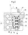
- Fig. 2 shows a section through an inventive directional valve in the assembled functional position.
- the inner design of the valve body 10 and of the base plate element 20 can also be seen here.
- the valve member 18 Arranged within the valve body 10 is the valve member 18 which can be driven via the external drive and which switches between the individual pressure lines S, P, R, A, B.
- This valve member 18 can either be driven by a piston drive, or it can also be electromotive or electromagnetic.
- the line guides can be seen within the base plate element 20.
- the standard lines S, P and R are arranged within the 21 leg of the base plate element, and the working lines B are located within the other leg 22 of the base plate element and A arranged. It can be seen here that a straight-line flow through the valve is possible with this arrangement, thus creating a valve with a high flow rate which, in contrast to so-called inline valves, makes use of the advantage of the base plate elements.
Landscapes
- Engineering & Computer Science (AREA)
- General Engineering & Computer Science (AREA)
- Mechanical Engineering (AREA)
- Physics & Mathematics (AREA)
- Fluid Mechanics (AREA)
- Electromagnetism (AREA)
- Valve Housings (AREA)
- Multiple-Way Valves (AREA)
Abstract
Description
- Die Erfindung betrifft ein Wegeventil in Grundplattenausführung mit einem Ventilkörper, in welchem mindestens ein zwischen Druckmittelleitungsanschlüssen schaltendes Ventilglied angeordnet ist, sowie mit einem Druckmittelleitungen enthaltenden Grundplattenelement mit welchem das Wegeventil mindestens mit einem Teil seiner Druckmittelanschlüsse in druckmittelschlüssigen Kontakt bringbar ist.
- Solche als Grundplatten-Ventile bezeichneten Wegeventile sind weit verbreitet. Bei bekannten Wegeventilen dieser Art ist jedem einzelnen Ventilkörper ein Grundplattenelement zugeordnet. Die Grundplattenelemente sind dabei in bekannten Ausführungen mit den entsprechenden Druckmittelkanälen versehen und haben an der Oberfläche, die mit dem Wegeventil in Kontakt zu bringen ist, entsprechende Anschlüsse. Die Grundplattenelemente selbst können bei bekannten Anordnungen in beliebiger Weise aneinandergereiht werden. Werden diese Grundplattenelemente mit Ventilen bestückt, so entsteht beispielsweise eine aus mehreren Ventilen bestehende Ventilgruppe. Die Führung von Druckmittelleitungen innerhalb der Grundplattenelemente ist bei Ventilen dieser Art genormt. Es gibt dabei Ausführungen, bei denen die Grundplatten lediglich die Druckmittelanschlüsse S, P und R aufweisen. P stellt den Druckmittelversorgungsanschluß dar, und R und S sind Entlüftungsleitungen. Bei Inline-Ventilen auf sogenannten Anschlußplatten werden die Arbeitsleitungen A und B direkt aus den Ventilen herausgeführt. Bei sogenannten Inline-Ventilen ohne Anschlußplatte werden sämtliche Druckmittelanschlüsse bzw. Druckmittelleitungen einzeln, d.h. ohne Grundplatte, geführt. Bei den zuerst benannten klassischen Grundplattenventilen sind neben den genannten Anschlüssen S, P und R auch die Arbeitsleitungen A und B durch das Grundplattenelement geführt. Der Vorteil von Inline-Ventilen, die auf Grundplatten verzichten, ist es, daß durch die direkte Herausführung der Anschlußleitungen ein großer Druckmitteldurchfluß erreicht wird. Bei Grundplattenventilen hingegen sind sämtliche Druckmittelleitungen sowie auch die Arbeitsleitungen über eine Seitenfläche des Ventilkörpers nach außen geführt. Das Grundplattenelement weist die entsprechenden Druckmittelanschlüsse ebenfalls an einer, nämlich an der mit dem Ventil zu bringenden Außenfläche auf. Dies führt dazu, daß die Druckmittelanschlüsse, insbesondere die Arbeitsleitungen, innerhalb des Grundplattenelementes entsprechend stark umgelenkt sind. Solche starken Umlenkungen behindern den Durchfluß von Druckmittel in erheblichem Maße. Bislang ist es nicht gelungen, die geradlinige Führung der Druckmittelleitungen, wie sie bei Inline-Ventilen vorliegt, auch für Grundplattenventile zu realisieren, bei denen sämtliche Leitungen innerhalb der Grundplattenelemente geführt werden.
- Mit der vorliegenden Erfindung hat man sich diesem Problem gewidmet und ein Wegeventil in Grundplattenausführung derart ausgestaltet, daß eine geradlinige Führung der über das Ventilglied schaltbaren Druckmittelleitungen realisiert ist. In der Lösung der vorstehend genannten Problemes ist bei einem Wegeventil der gattungsgemäßen Art erfindungsgemäß vorgeschlagen, daß das Grundplattenelement eine Öffnung aufweist, in welche der Ventilkörper zumindest teilweise einschiebbar ist und die in Kontakt zu bringenden Druckmittelanschlüsse innerhalb der öffnung und am entsprechenden Ventilkörperteil angeordnet sind.
- Weitere Ausgestaltungen der Erfindung sind in den Unteransprüchen angegeben. Durch eine solche erfindungsgemäße Ventilgestaltung ist es nun möglich, daß auf der einen Seite, d.h. an einer der Flanken der im Tiefenprofil beispielsweise keilförmigen Öffnung die genormten Druckmittelanschlüsse S, P und R an den Ventilkörper herangeführt werden, und an der gegenüberliegenden Flanke ohne Umlenkung der Druckmittelleitungen die Arbeitsleitungsanschlüsse aus dem Ventilkörper austreten und geradlinig in die entsprechende Flanke des Grundplattenelementes eintreten. Somit ergibt sich, daß die Leitungen S, P, R und A, B quasi parallel zueinander angeordnet sind und die Druckanschlüsse sich quasi gegenüberliegen. Es findet somit eine erheblich geradlinigere Durchströmung des Ventiles statt. Hiermit können unter Ausnutzung des Vorteiles, daß sämtliche Druckmittelanschlüsse innerhalb des Grundplattenelementes geführt sind, hohe Durchflüsse erreicht werden, wie sie ansonsten nur von grundplattenlosen Inline-Ventilen erreicht werden. In weiterer Ausgestaltung der Erfindung ist der in die Öffnung des Grundplattenelementes einzubringende Teil des Ventilkörpers sowie die öffnung selbst keilförmig ausgebildet. Dies ist in der Weise vorgenommen, daß sich die keilförmige Öffnung zum offenen Ende hin erweitert und zum Boden der öffnung des Grundplattenelementes hin verjüngt. Eine solche Ausbildung hat darüber hinaus erhebliche dichtungsmäßige Vorteile. Durch die keilförmige Ausbildung des Ventilkörperabschnittes sowie der Öffnung im Grundplattenelement wird während des Einschiebens des Ventilkörpers in die Öffnung nicht nur der Ventilkörper mit dem entsprechend keilförmigen Teil in die Öffnung hineingesenkt, sondern die in Kontakt zu bringenden Flankenflächen nähern sich während dieser Einschiebbewegung an, bis hin zu einer dichtenden Anpressung der Dichtelemente. In weiterer vorteilhafter Ausgestaltung sind Ventilkörper und Ventilgrundplattenelemente mit Rastelementen versehen, die den Ventilkörper in eingeschobener Position in Funktionslage arretiert halten.
- Die Erfindung ist in der Zeichnung dargestellt und im nachfolgenden näher beschrieben. Es zeigt:
- Fig. 1
- Ventil in demontierter Lage,
- Fig. 2
- Schnitt durch Ventil in montierter Funktionslage.
- Fig. 1 zeigt das Wegeventil in Grundplattenausführung in demontierter Stellung. Der Ventilkörper 10 selbst weist ein elektromagnetisches Antriebselement 11 auf, sowie einen keilförmigen Abschnitt 12. Innerhalb des keilförmigen Abschnittes 12 ist das verschiebbare Ventilglied angeordnet sowie Ansätze der zu schaltenden Druckmittelleitungen. An den abgeschrägten Flanken 13, 14 dieses keilförmigen Ansatzes 12 treten die entsprechenden Öffnungen 15 über die Flankenfläche 13, 14 aus. Im Bereich dieser Öffnungen sind Dichtungselemente 16 angeordnet, die hierbei über die ansonsten ebene Flankenfläche hinausragen und bei Erreichen der Montagestellung innerhalb des Öffnung 23 des Grundplattenelementes 20 an die abzudichtenden Stellen angepreßt werden. Zwischen dem Ventilantrieb 11 und dem keilförmigen Ansatz 12 ist eine Platte 17 angeordnet, die mit dem Grundplattenelement 20 in montierter Stellung zur Anlage kommt und darüber hinaus noch entsprechende Rastelemte 26 enthält, die mit dem Grundplattenelement in montierter Funktionslage zusammenwirken und den Ventilkörper 10 in dem Grundplattenelement 20 fixieren. Im unteren Bildteil von Fig. 1 ist das Grundplattenelement 20 dargestellt. Die Öffnung 23 ist entsprechend dem keilförmigen Absatz 12 des Ventilkörpers 10 entsprechend keilförmig ausgebildet. An den Flanken 24, 25 treten die entsprechenden Druckmittelanschlüsse aus, die in Fig. 2 noch näher dargestellt sind. Diejenige Außenwandung der öffnung, die hier nicht keilförmig ist, ist in Einschiebrichtung bis zum Grund der Öffnung hin durchbrochen, so daß das Grundplattenelement in der Seitenansicht U-förmig erscheint. Hierbei ist bereits dargestellt, daß die genormten Druckmittelleitungen S, P, R auf einer Seite, d.h. hierbei im Bereich des linken Schenkels 21, und die Arbeitsleitungen A und B innerhalb des rechten Schenkels 22 des Grundplattenelementes 20 angeordnet sind. Zwischen diesen Leitungen ist somit der Ventilkörper in montierter Funktionslage angeordnet. Dies erlaubt, was hierbei schon zu erkennen ist, eine sehr geradlinige Durchströmung des Grundplattenelementes 20.
- Fig. 2 zeigt einen Schnitt durch ein erfindungsgemäßes Wegeventil in montierter Funktionslage. Hierbei ist nun auch die innere Gestaltung des Ventilkörpers 10 sowie des Grundplattenelementes 20 zu erkennen. Innerhalb des Ventilkörpers 10 ist das über den externen Antrieb antreibbare Ventilglied 18 angeordnet, welches zwischen den einzelnen Druckleitungen S, P, R, A, B schaltet. Dieses Ventilglied 18 kann entweder selbst auch druckmittelbeaufschlagt über einen Kolbenantrieb angetrieben sein, oder aber auch elektromotorisch oder elektromagnetisch. Zu erkennen sind die Leitungsführungen innerhalb des Grundplattenelementes 20. Wie bereits in der Beschreibung zu Fig. 1 gesagt, sind innerhalb des 21 einen Schenkels des Grundplattenelementes die Standardleitungen S, P und R angeordnet, und innerhalb des anderen Schenkels 22 des Grundplattenelementes sind die Arbeitsleitungen B und A angeordnet. Zu erkennen ist hierbei, daß durch diese Anordnung eine geradlinige Durchströmung des Ventiles möglich ist und somit ein Ventil mit hohem Durchfluß geschaffen ist, welches im Gegensatz zu sogenannten Inline-Ventilen insgesamt vom Vorteil der Grundplattenelemente Gebrauch macht.
Claims (7)
- Wegeventil in Grundplattenausführung mit einem Ventilkörper, in welchem mindestens ein zwischen Druckmittelleitungsanschlüssen schaltendes Ventilglied angeordnet ist, sowie mit einem Druckmittelleitungen enthaltenden Grundplattenelement, mit welchem das Wegeventil mindestens mit einem Teil seiner Druckmittelanschlüsse in druckmittelschlüssigen Kontakt bringbar ist,
dadurch gekennzeichnet,
daß das Grundplattenelement (20) eine öffnung (23) aufweist, in welche der Ventilkörper (10) zumindest teilweise einschiebbar ist, und die in Kontakt zu bringenden Druckmittelanschlüsse (S, P, R, A, B) innerhalb der Öffnung (23) und am entsprechenden Ventilkörperteil (12) angeordnet sind. - Wegeventil in Grundplattenausführung nach Anspruch 1,
dadurch gekennzeichnet,
daß das in die Öffnung (23) des Grundplattenelementes (20) einzuschiebende Ventilkörperteil (10) einen keilförmigen Ansatz (12) aufweist, und die Öffnung (23) zur Aufnahme desselben entsprechend keilförmig ausgebildet ist. - Wegeventil in Grundplattenausführung nach Anspruch 2,
dadurch gekennzeichnet,
daß an den schrägen Flächen (13, 14) des keilförmigen Ventilkörperteiles (12) die Druckmittelanschlüsse (15) des Ventilkörpers (10), und an den entsprechenden schrägen Flächen (24, 25) der Öffnung (23) des Grundplattenelementes (20) die Druckmittelleitungsanschlüsse desselben angeordnet sind. - Wegeventil in Grundplattenausführung nach Anspruch 3,
dadurch gekennzeichnet,
daß Dichtungselemente (16) an den Druckmittelanschlüssen (15) des Ventilkörpers (10) oder des Grundplattenelementes (20) derart angeordnet sind, daß sie über die zueinander zu bringenden Flankenflächen (13, 14, 24, 25) hinausragen und bei Erreichen der Soll-Lage des keilförmigen Ventilkörperteiles (12) in der keilförmigen öffnung (23) dichtend zwischen den Flankenoberflächen anliegen. - Wegeventil in Grundplattenausführung nach Anspruch 4,
dadurch gekennzeichnet,
daß der Ventilkörper (10) und das Grundplattenelement (20) mit Rastelementen (26) versehen sind, welche den Ventilkörper (10) auf bzw. in dem Grundplattenelement (20) in funktionsgerechter Endmontagestellung fixieren. - Wegeventil in Grundplattenausführung nach Anspruch 5,
dadurch gekennzeichnet,
daß die Rastelemente (26) von außen zur Lösung der Rastverbindung zugänglich gestaltet sind. - Wegeventil in Grundplattenausführung nach einem oder mehreren der vorhergehenden Ansprüche,
dadurch gekennzeichnet,
daß die Seitenwandungen des Grundplattenelementes (20) im Bereich der Öffnung (23), die nicht die Flankenflächen (24, 25) der keilförmigen Tiefenkontur der öffnung (23) bilden, durchbrochen sind bis zum Boden der öffnung (23) derart, daß das Grundplattenelement (20) in Seitenansicht eine U-Form bildet.
Applications Claiming Priority (2)
| Application Number | Priority Date | Filing Date | Title |
|---|---|---|---|
| DE4412247A DE4412247A1 (de) | 1994-04-06 | 1994-04-06 | Wegeventil in Grundplattenausführung |
| DE4412247 | 1994-04-06 |
Publications (2)
| Publication Number | Publication Date |
|---|---|
| EP0676573A1 true EP0676573A1 (de) | 1995-10-11 |
| EP0676573B1 EP0676573B1 (de) | 1998-04-15 |
Family
ID=6514985
Family Applications (1)
| Application Number | Title | Priority Date | Filing Date |
|---|---|---|---|
| EP95250027A Expired - Lifetime EP0676573B1 (de) | 1994-04-06 | 1995-02-03 | Wegeventil in Grundplattenausführung |
Country Status (3)
| Country | Link |
|---|---|
| US (1) | US5819788A (de) |
| EP (1) | EP0676573B1 (de) |
| DE (2) | DE4412247A1 (de) |
Cited By (3)
| Publication number | Priority date | Publication date | Assignee | Title |
|---|---|---|---|---|
| DE19704656A1 (de) * | 1997-02-07 | 1998-08-13 | Gruenbeck Josef Wasseraufb | Einrichtung zur Lenkung, Steuerung, Regelung, Messung und Überwachung von Flüssigkeitsströmen und Wasseraufbereitungsanlage |
| EP1669649A1 (de) * | 2004-12-10 | 2006-06-14 | Eaton Corporation | Durchflussregelventil mit geneigter Dichtung |
| WO2013097918A1 (de) * | 2011-12-29 | 2013-07-04 | Robert Bosch Gmbh | Ventileinheit und ventilanordnung |
Families Citing this family (6)
| Publication number | Priority date | Publication date | Assignee | Title |
|---|---|---|---|---|
| DE19943691C2 (de) * | 1999-09-06 | 2003-03-13 | Rexroth Mecman Gmbh | Wegeventil |
| DE10107868A1 (de) * | 2001-02-20 | 2002-09-05 | Bosch Gmbh Robert | Pneumatisches Wegeventil |
| US6539971B2 (en) * | 2001-08-17 | 2003-04-01 | Eaton Corporation | Method and apparatus for mounting solenoid operated valve |
| CN101680562B (zh) * | 2008-02-01 | 2012-10-10 | 费斯托股份有限两合公司 | 带有手动辅助操作装置的阀装置 |
| CN108136499B (zh) * | 2015-10-02 | 2021-01-12 | 阿斯科公司 | 通过增材制造方法制成的用于歧管组的歧管和阀外壳组合件 |
| US10738800B2 (en) | 2015-10-02 | 2020-08-11 | Asco, L.P. | Combination manifold block, valve housing and spool valve assembly for a manifold bank |
Citations (4)
| Publication number | Priority date | Publication date | Assignee | Title |
|---|---|---|---|---|
| DE2048525B2 (de) * | 1970-10-02 | 1973-10-31 | Veb Kombinat Orsta-Hydraulik, X 7010 Leipzig | Verkettungselement für hydrau hsche und pneumatische Einschraub ventile |
| DE2166935B2 (de) * | 1971-05-21 | 1979-09-06 | Festo-Maschinenfabrik Gottlieb Stoll, 7300 Esslingen | Ventilanordnung |
| DE9214301U1 (de) * | 1992-09-11 | 1992-12-24 | Festo AG & Co, 73734 Esslingen | Elektro-pneumatische Steuereinrichtung |
| EP0606048A1 (de) * | 1993-01-06 | 1994-07-13 | IMI Norgren AG | Fluidische Ventileinheit |
Family Cites Families (5)
| Publication number | Priority date | Publication date | Assignee | Title |
|---|---|---|---|---|
| US3347260A (en) * | 1964-09-22 | 1967-10-17 | Lockheed Aircraft Corp | Cartridge valve assembly |
| DE2518465A1 (de) * | 1975-04-25 | 1976-11-04 | Hydromatik Gmbh | Verkettungssystem fuer hydraulische ventile |
| DE3271285D1 (en) * | 1982-01-28 | 1986-07-03 | Grove Valve & Regulator Co | Line removable valve structure with pipeline support means |
| DE4111890C2 (de) * | 1991-04-09 | 1995-04-20 | Mannesmann Ag | Ventilbatterie, insbesondere für gasförmige Medien |
| DE4143274C2 (de) * | 1991-12-27 | 1994-03-10 | Mannesmann Ag | Ventilbaugruppe in Modulbauweise |
-
1994
- 1994-04-06 DE DE4412247A patent/DE4412247A1/de not_active Withdrawn
-
1995
- 1995-02-03 DE DE59501878T patent/DE59501878D1/de not_active Expired - Lifetime
- 1995-02-03 EP EP95250027A patent/EP0676573B1/de not_active Expired - Lifetime
-
1996
- 1996-10-11 US US08/728,904 patent/US5819788A/en not_active Expired - Lifetime
Patent Citations (4)
| Publication number | Priority date | Publication date | Assignee | Title |
|---|---|---|---|---|
| DE2048525B2 (de) * | 1970-10-02 | 1973-10-31 | Veb Kombinat Orsta-Hydraulik, X 7010 Leipzig | Verkettungselement für hydrau hsche und pneumatische Einschraub ventile |
| DE2166935B2 (de) * | 1971-05-21 | 1979-09-06 | Festo-Maschinenfabrik Gottlieb Stoll, 7300 Esslingen | Ventilanordnung |
| DE9214301U1 (de) * | 1992-09-11 | 1992-12-24 | Festo AG & Co, 73734 Esslingen | Elektro-pneumatische Steuereinrichtung |
| EP0606048A1 (de) * | 1993-01-06 | 1994-07-13 | IMI Norgren AG | Fluidische Ventileinheit |
Cited By (4)
| Publication number | Priority date | Publication date | Assignee | Title |
|---|---|---|---|---|
| DE19704656A1 (de) * | 1997-02-07 | 1998-08-13 | Gruenbeck Josef Wasseraufb | Einrichtung zur Lenkung, Steuerung, Regelung, Messung und Überwachung von Flüssigkeitsströmen und Wasseraufbereitungsanlage |
| US6136196A (en) * | 1997-02-07 | 2000-10-24 | Grunbeck Wasseraufbereitung Gmbh | Device for controlling, guiding, adjusting, measuring and monitoring liquid flows, and water treatment facility |
| EP1669649A1 (de) * | 2004-12-10 | 2006-06-14 | Eaton Corporation | Durchflussregelventil mit geneigter Dichtung |
| WO2013097918A1 (de) * | 2011-12-29 | 2013-07-04 | Robert Bosch Gmbh | Ventileinheit und ventilanordnung |
Also Published As
| Publication number | Publication date |
|---|---|
| EP0676573B1 (de) | 1998-04-15 |
| US5819788A (en) | 1998-10-13 |
| DE59501878D1 (de) | 1998-05-20 |
| DE4412247A1 (de) | 1995-10-12 |
Similar Documents
| Publication | Publication Date | Title |
|---|---|---|
| DE2606952A1 (de) | Einhebel-mischventil | |
| DE2306480A1 (de) | Schaltbares, insbesondere elektromagnetisch schaltbares, hochdruckventil | |
| DE69704592T2 (de) | Vorgesteuertes Wahlventil | |
| EP0676573B1 (de) | Wegeventil in Grundplattenausführung | |
| DE3340291A1 (de) | Druckmittelzylinder | |
| EP0733810A2 (de) | Modulare Ventilanordnung | |
| DE1750092A1 (de) | Mehrwegeventil | |
| DE1267045B (de) | Steuerschieber | |
| WO1989006764A2 (en) | Process and device for controlling the admission of a medium into at least one leakage chamber of a valve device | |
| DE2826538A1 (de) | Schliessventil | |
| DE1425586B2 (de) | Montagetafel fuer ventile | |
| EP0093359B1 (de) | Wegeventil | |
| DE2923534C2 (de) | Gerät zum Steuern eines Druckmittels, insbesondere Mehrfachsteuergerät für hydraulischen Schreitausbau | |
| DE2754242A1 (de) | Eckumlenkung fuer treibstangen, insbesondere fuer treibstangen von oberlichtoeffnern | |
| DE2850590A1 (de) | Elektromagnetventil, insbesondere zur verwendung bei hydraulischen steuerungen in bergbau-untertagebetrieben | |
| DE4303365B4 (de) | Selbsttätig sperrendes Stellelement | |
| DE10158252A1 (de) | Verschlussvorrichtung für eine automatische Trommeltür | |
| CH674684A5 (de) | Elektrischer geraeteschalter mit einer vorrichtung zum einstellen und/oder ausgleichen des vorlaufweges des betaetigers. | |
| DE2152012C2 (de) | Ventilanordnung | |
| DE4230713A1 (de) | Mehrteiliges Stufengehäuse | |
| DE20300024U1 (de) | Aufbau zur Befestigung von Knöpfen und einer Handhabe an einem Schaltfeld eines Ofens | |
| DE19613005C1 (de) | Funktionseinheit für fluidische Systeme | |
| DE29620916U1 (de) | Rückschlagventil mit im wesentlichen rotationssymmetrischer Strömungsführung | |
| DE4125815C2 (de) | Ventil, insbes. pneumatisches Schalt-, Stetig-, Vorsteuerventil u. dgl. | |
| DE3229682A1 (de) | Mehrwegeventil |
Legal Events
| Date | Code | Title | Description |
|---|---|---|---|
| PUAI | Public reference made under article 153(3) epc to a published international application that has entered the european phase |
Free format text: ORIGINAL CODE: 0009012 |
|
| AK | Designated contracting states |
Kind code of ref document: A1 Designated state(s): DE FR GB IT SE |
|
| 17P | Request for examination filed |
Effective date: 19950907 |
|
| 17Q | First examination report despatched |
Effective date: 19961220 |
|
| GRAG | Despatch of communication of intention to grant |
Free format text: ORIGINAL CODE: EPIDOS AGRA |
|
| GRAG | Despatch of communication of intention to grant |
Free format text: ORIGINAL CODE: EPIDOS AGRA |
|
| GRAH | Despatch of communication of intention to grant a patent |
Free format text: ORIGINAL CODE: EPIDOS IGRA |
|
| GRAH | Despatch of communication of intention to grant a patent |
Free format text: ORIGINAL CODE: EPIDOS IGRA |
|
| GRAA | (expected) grant |
Free format text: ORIGINAL CODE: 0009210 |
|
| AK | Designated contracting states |
Kind code of ref document: B1 Designated state(s): DE FR GB IT SE |
|
| ET | Fr: translation filed | ||
| GBT | Gb: translation of ep patent filed (gb section 77(6)(a)/1977) |
Effective date: 19980421 |
|
| ITF | It: translation for a ep patent filed | ||
| REF | Corresponds to: |
Ref document number: 59501878 Country of ref document: DE Date of ref document: 19980520 |
|
| PLBE | No opposition filed within time limit |
Free format text: ORIGINAL CODE: 0009261 |
|
| STAA | Information on the status of an ep patent application or granted ep patent |
Free format text: STATUS: NO OPPOSITION FILED WITHIN TIME LIMIT |
|
| 26N | No opposition filed | ||
| REG | Reference to a national code |
Ref country code: GB Ref legal event code: IF02 |
|
| PGFP | Annual fee paid to national office [announced via postgrant information from national office to epo] |
Ref country code: SE Payment date: 20020225 Year of fee payment: 8 |
|
| PG25 | Lapsed in a contracting state [announced via postgrant information from national office to epo] |
Ref country code: SE Free format text: LAPSE BECAUSE OF NON-PAYMENT OF DUE FEES Effective date: 20030204 |
|
| EUG | Se: european patent has lapsed | ||
| PGFP | Annual fee paid to national office [announced via postgrant information from national office to epo] |
Ref country code: GB Payment date: 20050131 Year of fee payment: 11 |
|
| PGFP | Annual fee paid to national office [announced via postgrant information from national office to epo] |
Ref country code: FR Payment date: 20050210 Year of fee payment: 11 |
|
| PG25 | Lapsed in a contracting state [announced via postgrant information from national office to epo] |
Ref country code: GB Free format text: LAPSE BECAUSE OF NON-PAYMENT OF DUE FEES Effective date: 20060203 |
|
| PGFP | Annual fee paid to national office [announced via postgrant information from national office to epo] |
Ref country code: IT Payment date: 20060228 Year of fee payment: 12 |
|
| GBPC | Gb: european patent ceased through non-payment of renewal fee |
Effective date: 20060203 |
|
| REG | Reference to a national code |
Ref country code: FR Ref legal event code: ST Effective date: 20061031 |
|
| PG25 | Lapsed in a contracting state [announced via postgrant information from national office to epo] |
Ref country code: FR Free format text: LAPSE BECAUSE OF NON-PAYMENT OF DUE FEES Effective date: 20060228 |
|
| PG25 | Lapsed in a contracting state [announced via postgrant information from national office to epo] |
Ref country code: IT Free format text: LAPSE BECAUSE OF NON-PAYMENT OF DUE FEES Effective date: 20070203 |
|
| PGFP | Annual fee paid to national office [announced via postgrant information from national office to epo] |
Ref country code: DE Payment date: 20100414 Year of fee payment: 16 |
|
| REG | Reference to a national code |
Ref country code: DE Ref legal event code: R119 Ref document number: 59501878 Country of ref document: DE Effective date: 20110901 |
|
| PG25 | Lapsed in a contracting state [announced via postgrant information from national office to epo] |
Ref country code: DE Free format text: LAPSE BECAUSE OF NON-PAYMENT OF DUE FEES Effective date: 20110901 |