EP0676590B1 - Gasturbinenbrennkammer - Google Patents
Gasturbinenbrennkammer Download PDFInfo
- Publication number
- EP0676590B1 EP0676590B1 EP95301294A EP95301294A EP0676590B1 EP 0676590 B1 EP0676590 B1 EP 0676590B1 EP 95301294 A EP95301294 A EP 95301294A EP 95301294 A EP95301294 A EP 95301294A EP 0676590 B1 EP0676590 B1 EP 0676590B1
- Authority
- EP
- European Patent Office
- Prior art keywords
- combustion chamber
- fuel
- ports
- air
- gas turbine
- Prior art date
- Legal status (The legal status is an assumption and is not a legal conclusion. Google has not performed a legal analysis and makes no representation as to the accuracy of the status listed.)
- Expired - Lifetime
Links
- 238000002485 combustion reaction Methods 0.000 title claims description 69
- 239000000446 fuel Substances 0.000 claims description 40
- 238000011144 upstream manufacturing Methods 0.000 claims description 11
- 239000000203 mixture Substances 0.000 claims description 10
- 238000003491 array Methods 0.000 claims description 4
- 238000001816 cooling Methods 0.000 description 4
- 238000013021 overheating Methods 0.000 description 4
- 230000000694 effects Effects 0.000 description 3
- 230000001627 detrimental effect Effects 0.000 description 1
- 239000007788 liquid Substances 0.000 description 1
- 230000001141 propulsive effect Effects 0.000 description 1
Images
Classifications
-
- F—MECHANICAL ENGINEERING; LIGHTING; HEATING; WEAPONS; BLASTING
- F23—COMBUSTION APPARATUS; COMBUSTION PROCESSES
- F23R—GENERATING COMBUSTION PRODUCTS OF HIGH PRESSURE OR HIGH VELOCITY, e.g. GAS-TURBINE COMBUSTION CHAMBERS
- F23R3/00—Continuous combustion chambers using liquid or gaseous fuel
- F23R3/02—Continuous combustion chambers using liquid or gaseous fuel characterised by the air-flow or gas-flow configuration
- F23R3/04—Air inlet arrangements
- F23R3/10—Air inlet arrangements for primary air
- F23R3/12—Air inlet arrangements for primary air inducing a vortex
-
- F—MECHANICAL ENGINEERING; LIGHTING; HEATING; WEAPONS; BLASTING
- F23—COMBUSTION APPARATUS; COMBUSTION PROCESSES
- F23R—GENERATING COMBUSTION PRODUCTS OF HIGH PRESSURE OR HIGH VELOCITY, e.g. GAS-TURBINE COMBUSTION CHAMBERS
- F23R3/00—Continuous combustion chambers using liquid or gaseous fuel
- F23R3/02—Continuous combustion chambers using liquid or gaseous fuel characterised by the air-flow or gas-flow configuration
- F23R3/04—Air inlet arrangements
- F23R3/045—Air inlet arrangements using pipes
Definitions
- This invention relates to combustion apparatus for a gas turbine engine and is particularly concerned with the efficient mixing of fuel and air in such combustion apparatus.
- the combustion apparatus of a gas turbine engine is required to operate over a wide range of conditions. It is important that throughout this range of operating conditions, the fuel and air mixture which is directed into the apparatus is as thoroughly mixed as possible. If such thorough mixing is not achieved, then following combustion of the mixture, zones of combustion products will appear which are hotter than the remainder of the combustion products. This gives rise to variations in the temperature distribution of the combustion products as they exit the combustion apparatus. As a direct consequence of this, the nozzle guide vanes and other parts of the turbine which normally lie downstream of the combustion apparatus are subjected to localised overheating.
- GB736823 discloses an arrangement of nozzles formed in an inner combustion chamber wall so as to direct jets of air towards an associated fuel nozzle. This provides a toroidal ring of swirling air around each nozzle.
- US3134229 discloses a combustion chamber comprising a circumferential row of vortex air generations in its closed end. Fuel is introduced directly into the vortices to provide mixing of fuel and air.
- a gas turbine engine combustion apparatus comprising an annular combustion chamber having a plurality of fuel nozzles (27) at its upstream end to direct a mixture of fuel and air into said chamber, each of said fuel nozzles (27) being adapted to swirl the fuel and air mixture directed therefrom in a given direction about its longitudinal axis (31), said combustion chamber being defined by radially inner and outer generally axially extending annular walls (19,20), each of said radially inner and outer walls (19,20) being provided with ports (34,35), at least in the upstream region thereof, for the entry of air into said combustion chamber said ports (34,35) being arranged in circumferentially extending arrays, the or each array of said ports in said radially outer combustion chamber wall (20) being aligned with a corresponding array of said ports in the radially inner combustion chamber wall such that the ports (34,35) in each of the combustion chamber walls (19,20) are positioned so that they oppose each other characterised in that each array comprises circum
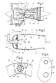
- Fig 1 is a sectioned side view of a ducted fan gas turbine engine which includes combustion apparatus in accordance with the present invention.
- Fig 2 is a sectioned side view on an enlarged scale of a part of the combustion apparatus of the ducted fan gas turbine engine shown in Fig 1.
- Fig 3 is a view on arrow A of Fig 2 showing the upstream end of the combustion apparatus.
- Fig 4 is a view on arrow B of Fig 2 showing part of the wall of the combustion apparatus.
- a ducted fan gas turbine engine generally indicated at 10 is of conventional overall configuration and operation.
- air drawn in by a fan 11 at the upstream end of the engine is compressed by two axial flow compressors 12 and 13 before being directed into combustion apparatus 14 in accordance with the present invention.
- combustion apparatus 14 There the compressed air is mixed with liquid fuel and the mixture combusted.
- the resultant hot combustion products then expand through a series of turbines 15, 16 and 17 before being exhausted through a propulsive nozzle 18.
- the combustion apparatus 14 can be seen more clearly if reference is now made to Fig 2.
- the combustion apparatus 14 is of the annular type. It comprises two generally axially extending, radially spaced apart annular cross-section walls 19 and 20 which are interconnected at their upstream ends by a curved wall 21.
- the downstream ends of the combustion apparatus walls 19 and 20 are connected to an annular array of nozzle guide vanes (not shown) which constitute the upstream end of the first turbine 15.
- the walls 19, 20 and 21 thereby define a combustion chamber 22.
- Compressed air exhausted from the compressors 12 and 13 is directed to a region 23 immediately upstream of the combustion apparatus 14. Some of that air passes through a plurality of apertures 24 provided in the curved wall 21. Immediately downstream of the curved wall 21 there is provided a further wall 25 which is also apertured to provide a series of further apertures 26 which are aligned with the apertures 24 in the curved wall 21.
- the apertures 26 in the further wall 25 each receive the downstream end of a generally L-shaped fuel nozzle 27 which also passes through an aperture 24 in the curved wall.
- the fuel nozzle 27 downstream end is provided with an annular array of swirler vanes 28, which can also be seen in Fig 3.
- the assembly of swirler vanes 28 actually interconnects the fuel nozzle 27 downstream end and the further wall 25.
- the air which passes through the apertures 24 in the curved wall 21 is subsequently swirled by the swirler vanes 28 in a generally anti-clockwise direction when viewed in the upstream direction and as indicated by the arrows 29 in Fig 3.
- This swirling of the air flow promotes mixing of the air with fuel which is sprayed in a conical jet 30 from the downstream end of the fuel nozzle 27. Consequently a swirling flow of fuel and air is created which swirls about the longitudinal axis 31 of the fuel nozzle 27.
- each of the combustion chamber walls 19 and 20 is provided with an annular array of the ports 34 and 35 towards its upstream end.
- Each port 34 and 35 is in the form of a short open ended pipe which protrudes into the combustion chamber 22.
- the end of each port 34 and 35 which protrudes into the combustion chamber 32 is scarfed.
- Each annular annular array of ports 34 and 35 comprises circumferentially alternate small and large diameter ports 34 and 35, one of each of which can be seen in plan view in Fig 4.
- the ports 34 and 35 in each of the combustion chamber walls 19 and 20 are so positioned that they oppose each other so that one small diameter port 34 opposes a large diameter port 35. This can be seen most clearly in Fig 3.
- the ports 34 and 35 are so positioned circumferentially in the walls 19 and 20 that the high pressure air exhausted from the larger ports 35 tends to oppose the direction of swirl of the fuel and air mixture from the fuel nozzles 27.
- Fig 3 shows this effect with the size of the arrows associated with the ports 34 and 35 being proportional to the air exhausted from those ports 34 and 35.
Landscapes
- Engineering & Computer Science (AREA)
- Chemical & Material Sciences (AREA)
- Combustion & Propulsion (AREA)
- Mechanical Engineering (AREA)
- General Engineering & Computer Science (AREA)
- Turbine Rotor Nozzle Sealing (AREA)
Claims (4)
- Verbrennungsvorrichtung (14) für ein Gasturbinentriebwerk mit einer Ringbrennkammer, die mehrere Brennstoffdüsen (27) am stromaufwärtigen Ende besitzt, um eine Mischung von Brennstoff und Luft in die Kammer einzuspritzen, wobei jede Brennstoffdüse (27) so angeordnet ist, daß das Brennstoff/Luft-Gemisch, das von diesen Düsen ausgeht, in einer gegebenen Richtung um die Längsachse (31) verwirbelt wird, wobei die Brennkammer durch radial innere und radial äußere, allgemein axial verlaufende Ringwände (19, 20) definiert ist, von denen jede der radial inneren und äußeren Wände (19, 20) mit Öffnungen (34, 35) wenigstens im stromaufwärtigen Bereich versehen ist, damit Luft in die Brennkammer eintreten kann, und wobei die Öffnungen (34, 35) in in Umfangsrichtung verlaufenden Gruppen angeordnet sind und jede Gruppe der Öffnungen in der radial äußeren Brennkammerwand (20) auf eine entsprechende Gruppe von Öffnungen in der radial inneren Brennkammerwand derart ausgerichtet ist, daß die Öffnungen (34, 35) in jeder Brennkammerwand (19, 20) so angeordnet sind, daß sie einander gegenüberliegen,
dadurch gekennzeichnet, daß die Gruppen aus in Umfangsrichtung abwechselnden Öffnungen (34, 35) kleinen und großen Durchmessers bestehen, wobei eine Öffnung (34) kleinen Durchmessers so angeordnet ist, daß sie einer Öffnung (35) großen Durchmessers gegenüberliegt, wobei die Anordnung der Öffnungen derart ist, daß die aus einer Öffnung (35) großen Durchmessers ausgeblasene Luft der gegebenen Verwirbelungsrichtung des Brennstoff/Luft-Gemischs entgegenwirkt, das aus jeder Brennstoffdüse (27) austritt. - Verbrennungsvorrichtung für ein Gasturbinentriebwerk nach Anspruch 1,
dadurch gekennzeichnet, daß jede Brennstoffdüse (27) Mittel aufweist, die einen im wesentlichen konischen Brennstoffstrahl in die Brennkammer richten, und daß eine ringförmige Anordnung von Wirbelschaufeln (28) um die Brennstoffaustrittsrichtmittel angeordnet sind, um eine Verwirbelung des Brennstoffs mit der Luftströmung durch die Verwirbelungsschaufeln (28) zu schaffen. - Verbrennungsvorrichtung für ein Gasturbinentriebwerk nach den Ansprüchen 1 oder 2,
dadurch gekennzeichnet, daß jede der Öffnungen (34, 35) die Form eines kurzen, am Ende offenen Rohrstummels aufweist, der in die Brennkammer einsteht. - Verbrennungsvorrichtung für ein Gasturbinentriebwerk nach Anspruch 3,
dadurch gekennzeichnet, daß die kurzen offenen Rohrstummel an ihrem in die Brennkammer einstehenden Ende angeschärft sind.
Applications Claiming Priority (2)
| Application Number | Priority Date | Filing Date | Title |
|---|---|---|---|
| GB9407029A GB9407029D0 (en) | 1994-04-08 | 1994-04-08 | Gas turbine engine combustion apparatus |
| GB9407029 | 1994-04-08 |
Publications (2)
| Publication Number | Publication Date |
|---|---|
| EP0676590A1 EP0676590A1 (de) | 1995-10-11 |
| EP0676590B1 true EP0676590B1 (de) | 1998-06-17 |
Family
ID=10753270
Family Applications (1)
| Application Number | Title | Priority Date | Filing Date |
|---|---|---|---|
| EP95301294A Expired - Lifetime EP0676590B1 (de) | 1994-04-08 | 1995-02-28 | Gasturbinenbrennkammer |
Country Status (4)
| Country | Link |
|---|---|
| US (1) | US5590530A (de) |
| EP (1) | EP0676590B1 (de) |
| DE (1) | DE69502984T2 (de) |
| GB (1) | GB9407029D0 (de) |
Cited By (1)
| Publication number | Priority date | Publication date | Assignee | Title |
|---|---|---|---|---|
| DE102011012414A1 (de) | 2011-02-25 | 2012-08-30 | Rolls-Royce Deutschland Ltd & Co Kg | Gasturbinenbrennkammer |
Families Citing this family (11)
| Publication number | Priority date | Publication date | Assignee | Title |
|---|---|---|---|---|
| FR2748088B1 (fr) * | 1996-04-24 | 1998-05-29 | Snecma | Optimisation du melange de gaz brules dans une chambre de combustion annulaire |
| US6606861B2 (en) * | 2001-02-26 | 2003-08-19 | United Technologies Corporation | Low emissions combustor for a gas turbine engine |
| US6675587B2 (en) | 2002-03-21 | 2004-01-13 | United Technologies Corporation | Counter swirl annular combustor |
| US8590313B2 (en) * | 2008-07-30 | 2013-11-26 | Rolls-Royce Corporation | Precision counter-swirl combustor |
| US8631638B2 (en) | 2010-08-11 | 2014-01-21 | Rene Carlos | Method, system and apparatus for providing water to a heat engine via a dammed water source |
| US20120038165A1 (en) * | 2010-08-11 | 2012-02-16 | Rene Carlos | System and method for generating power in a dam |
| WO2014149081A1 (en) * | 2013-03-15 | 2014-09-25 | Rolls-Royce Corporation | Counter swirl doublet combustor |
| US20170059159A1 (en) | 2015-08-25 | 2017-03-02 | Rolls-Royce Corporation | Cmc combustor shell with integral chutes |
| US10823418B2 (en) * | 2017-03-02 | 2020-11-03 | General Electric Company | Gas turbine engine combustor comprising air inlet tubes arranged around the combustor |
| US11248789B2 (en) | 2018-12-07 | 2022-02-15 | Raytheon Technologies Corporation | Gas turbine engine with integral combustion liner and turbine nozzle |
| CN116658932B (zh) * | 2022-02-18 | 2025-09-16 | 通用电气公司 | 具有带旋流轮叶的稀释开口的燃烧器衬套 |
Family Cites Families (14)
| Publication number | Priority date | Publication date | Assignee | Title |
|---|---|---|---|---|
| DE904255C (de) * | 1944-07-12 | 1954-02-15 | Daimler Benz Ag | Brennkammer fuer Strahltriebwerke |
| BE502037A (de) * | 1950-03-21 | |||
| GB736823A (en) * | 1953-01-19 | 1955-09-14 | Lucas Industries Ltd | Engine combustion chambers |
| US3134229A (en) * | 1961-10-02 | 1964-05-26 | Gen Electric | Combustion chamber |
| US3643430A (en) * | 1970-03-04 | 1972-02-22 | United Aircraft Corp | Smoke reduction combustion chamber |
| FR2106485B1 (de) * | 1970-09-14 | 1975-02-21 | Mitsubishi Heavy Ind Ltd | |
| US3874169A (en) * | 1971-01-14 | 1975-04-01 | Stal Laval Turbin Ab | Combustion chamber for gas turbines |
| US3811278A (en) * | 1973-02-01 | 1974-05-21 | Gen Electric | Fuel injection apparatus |
| GB1511849A (en) * | 1974-11-28 | 1978-05-24 | Secr Defence | Combustion apparatus |
| US4271675A (en) * | 1977-10-21 | 1981-06-09 | Rolls-Royce Limited | Combustion apparatus for gas turbine engines |
| GB2020371B (en) * | 1978-05-04 | 1982-09-29 | Penny Turbines Ltd Noel | Gas turbine combustion chamber |
| US4301657A (en) * | 1978-05-04 | 1981-11-24 | Caterpillar Tractor Co. | Gas turbine combustion chamber |
| GB2099978A (en) * | 1981-05-11 | 1982-12-15 | Rolls Royce | Gas turbine engine combustor |
| FR2674317B1 (fr) * | 1991-03-20 | 1993-05-28 | Snecma | Chambre de combustion de turbomachine comportant un reglage du debit de comburant. |
-
1994
- 1994-04-08 GB GB9407029A patent/GB9407029D0/en active Pending
-
1995
- 1995-02-28 DE DE69502984T patent/DE69502984T2/de not_active Expired - Lifetime
- 1995-02-28 EP EP95301294A patent/EP0676590B1/de not_active Expired - Lifetime
- 1995-03-14 US US08/404,151 patent/US5590530A/en not_active Expired - Lifetime
Cited By (1)
| Publication number | Priority date | Publication date | Assignee | Title |
|---|---|---|---|---|
| DE102011012414A1 (de) | 2011-02-25 | 2012-08-30 | Rolls-Royce Deutschland Ltd & Co Kg | Gasturbinenbrennkammer |
Also Published As
| Publication number | Publication date |
|---|---|
| US5590530A (en) | 1997-01-07 |
| DE69502984T2 (de) | 1998-10-15 |
| GB9407029D0 (en) | 1994-06-08 |
| DE69502984D1 (de) | 1998-07-23 |
| EP0676590A1 (de) | 1995-10-11 |
Similar Documents
| Publication | Publication Date | Title |
|---|---|---|
| JP4097734B2 (ja) | ガスタービン用の三通路ディフューザ | |
| EP0587580B1 (de) | Gasturbinenbrennkammer | |
| US2856755A (en) | Combustion chamber with diverse combustion and diluent air paths | |
| US5289686A (en) | Low nox gas turbine combustor liner with elliptical apertures for air swirling | |
| EP0550218B1 (de) | Brennkammer einer Gasturbine | |
| US3099134A (en) | Combustion chambers | |
| EP0471437B1 (de) | Gasturbinenbrennkammer | |
| EP0672868B1 (de) | Mittel zur Minderung der unverbrannten Werkstoffen in einer Gasturbinenbrennkammer | |
| EP0732546B1 (de) | Brennkammer und Verfahren zum Betrieb einer mit gasförmigen oder flüssigem Brennstoff betriebenen Gasturbine | |
| US4193260A (en) | Combustion apparatus | |
| US5289687A (en) | One-piece cowl for a double annular combustor | |
| EP0676590B1 (de) | Gasturbinenbrennkammer | |
| JPH09501486A (ja) | 燃料噴射装置及び該燃料噴射装置の運転方法 | |
| EP3967929B1 (de) | Drallvorrichtung für kraftstoffdüse | |
| US4944152A (en) | Augmented turbine combustor cooling | |
| US11703225B2 (en) | Swirler opposed dilution with shaped and cooled fence | |
| CN115899765B (zh) | 用于降低排放的带有旋流轮叶的环形燃烧器稀释 | |
| US5927066A (en) | Turbine including a stored energy combustor | |
| KR20040018480A (ko) | 냉각 공기 플레넘 리세스를 구비하고 질소산화물 배출이적은 연소 라이너 | |
| US3019605A (en) | Combustion apparatus of gas turbine engines with means controlling air flow conditions in the combustion apparatus | |
| WO2003100242A1 (en) | Turbine engine apparatus and method | |
| CN116804463B (zh) | 提供带有反向涡流气流的圆顶偏转器腔的圆顶结构 | |
| JPS59158916A (ja) | ガスタ−ビンエンジン用燃焼器 | |
| US12196422B2 (en) | Combustor with secondary fuel nozzle in dilution fence | |
| US3000182A (en) | Can burner design |
Legal Events
| Date | Code | Title | Description |
|---|---|---|---|
| PUAI | Public reference made under article 153(3) epc to a published international application that has entered the european phase |
Free format text: ORIGINAL CODE: 0009012 |
|
| 17P | Request for examination filed |
Effective date: 19950816 |
|
| AK | Designated contracting states |
Kind code of ref document: A1 Designated state(s): DE FR GB |
|
| 17Q | First examination report despatched |
Effective date: 19970506 |
|
| GRAG | Despatch of communication of intention to grant |
Free format text: ORIGINAL CODE: EPIDOS AGRA |
|
| GRAG | Despatch of communication of intention to grant |
Free format text: ORIGINAL CODE: EPIDOS AGRA |
|
| GRAH | Despatch of communication of intention to grant a patent |
Free format text: ORIGINAL CODE: EPIDOS IGRA |
|
| GRAH | Despatch of communication of intention to grant a patent |
Free format text: ORIGINAL CODE: EPIDOS IGRA |
|
| GRAA | (expected) grant |
Free format text: ORIGINAL CODE: 0009210 |
|
| AK | Designated contracting states |
Kind code of ref document: B1 Designated state(s): DE FR GB |
|
| REF | Corresponds to: |
Ref document number: 69502984 Country of ref document: DE Date of ref document: 19980723 |
|
| ET | Fr: translation filed | ||
| PLBE | No opposition filed within time limit |
Free format text: ORIGINAL CODE: 0009261 |
|
| STAA | Information on the status of an ep patent application or granted ep patent |
Free format text: STATUS: NO OPPOSITION FILED WITHIN TIME LIMIT |
|
| 26N | No opposition filed | ||
| REG | Reference to a national code |
Ref country code: GB Ref legal event code: IF02 |
|
| PGFP | Annual fee paid to national office [announced via postgrant information from national office to epo] |
Ref country code: DE Payment date: 20140227 Year of fee payment: 20 |
|
| PGFP | Annual fee paid to national office [announced via postgrant information from national office to epo] |
Ref country code: FR Payment date: 20140220 Year of fee payment: 20 |
|
| PGFP | Annual fee paid to national office [announced via postgrant information from national office to epo] |
Ref country code: GB Payment date: 20140227 Year of fee payment: 20 |
|
| REG | Reference to a national code |
Ref country code: DE Ref legal event code: R071 Ref document number: 69502984 Country of ref document: DE |
|
| REG | Reference to a national code |
Ref country code: GB Ref legal event code: PE20 Expiry date: 20150227 |
|
| PG25 | Lapsed in a contracting state [announced via postgrant information from national office to epo] |
Ref country code: GB Free format text: LAPSE BECAUSE OF EXPIRATION OF PROTECTION Effective date: 20150227 |