EP0676798A2 - Feldeffekttransistor mit isoliertem Gate und asymmetrischem Kanal und Verfahren zur Herstellung - Google Patents
Feldeffekttransistor mit isoliertem Gate und asymmetrischem Kanal und Verfahren zur Herstellung Download PDFInfo
- Publication number
- EP0676798A2 EP0676798A2 EP95104910A EP95104910A EP0676798A2 EP 0676798 A2 EP0676798 A2 EP 0676798A2 EP 95104910 A EP95104910 A EP 95104910A EP 95104910 A EP95104910 A EP 95104910A EP 0676798 A2 EP0676798 A2 EP 0676798A2
- Authority
- EP
- European Patent Office
- Prior art keywords
- dopant
- region
- electrode
- gate structure
- dopant region
- Prior art date
- Legal status (The legal status is an assumption and is not a legal conclusion. Google has not performed a legal analysis and makes no representation as to the accuracy of the status listed.)
- Withdrawn
Links
- 230000005669 field effect Effects 0.000 title claims abstract description 23
- 238000000034 method Methods 0.000 title claims description 30
- 239000002019 doping agent Substances 0.000 claims abstract description 81
- 239000007943 implant Substances 0.000 claims abstract description 37
- 239000012535 impurity Substances 0.000 claims abstract description 23
- 239000000463 material Substances 0.000 claims abstract description 21
- 239000004065 semiconductor Substances 0.000 claims description 36
- 239000000758 substrate Substances 0.000 claims description 29
- 125000006850 spacer group Chemical group 0.000 claims description 5
- 230000000295 complement effect Effects 0.000 abstract description 6
- 230000003071 parasitic effect Effects 0.000 abstract 1
- 229910021420 polycrystalline silicon Inorganic materials 0.000 description 29
- 229920005591 polysilicon Polymers 0.000 description 29
- 230000015572 biosynthetic process Effects 0.000 description 10
- 150000004767 nitrides Chemical class 0.000 description 6
- 229920002120 photoresistant polymer Polymers 0.000 description 6
- ZOXJGFHDIHLPTG-UHFFFAOYSA-N Boron Chemical compound [B] ZOXJGFHDIHLPTG-UHFFFAOYSA-N 0.000 description 5
- 229910052796 boron Inorganic materials 0.000 description 5
- 229910021332 silicide Inorganic materials 0.000 description 5
- FVBUAEGBCNSCDD-UHFFFAOYSA-N silicide(4-) Chemical compound [Si-4] FVBUAEGBCNSCDD-UHFFFAOYSA-N 0.000 description 5
- 241000293849 Cordylanthus Species 0.000 description 3
- OAICVXFJPJFONN-UHFFFAOYSA-N Phosphorus Chemical compound [P] OAICVXFJPJFONN-UHFFFAOYSA-N 0.000 description 3
- 230000000694 effects Effects 0.000 description 3
- 238000004519 manufacturing process Methods 0.000 description 3
- 229910052698 phosphorus Inorganic materials 0.000 description 3
- 239000011574 phosphorus Substances 0.000 description 3
- BOTDANWDWHJENH-UHFFFAOYSA-N Tetraethyl orthosilicate Chemical compound CCO[Si](OCC)(OCC)OCC BOTDANWDWHJENH-UHFFFAOYSA-N 0.000 description 2
- 229910052785 arsenic Inorganic materials 0.000 description 2
- RQNWIZPPADIBDY-UHFFFAOYSA-N arsenic atom Chemical compound [As] RQNWIZPPADIBDY-UHFFFAOYSA-N 0.000 description 2
- 229910052581 Si3N4 Inorganic materials 0.000 description 1
- 230000001413 cellular effect Effects 0.000 description 1
- 239000002800 charge carrier Substances 0.000 description 1
- 239000004020 conductor Substances 0.000 description 1
- 230000007423 decrease Effects 0.000 description 1
- 230000003247 decreasing effect Effects 0.000 description 1
- 238000005137 deposition process Methods 0.000 description 1
- 238000002955 isolation Methods 0.000 description 1
- 230000000873 masking effect Effects 0.000 description 1
- 230000015654 memory Effects 0.000 description 1
- 230000003647 oxidation Effects 0.000 description 1
- 238000007254 oxidation reaction Methods 0.000 description 1
- 238000002360 preparation method Methods 0.000 description 1
- HQVNEWCFYHHQES-UHFFFAOYSA-N silicon nitride Chemical compound N12[Si]34N5[Si]62N3[Si]51N64 HQVNEWCFYHHQES-UHFFFAOYSA-N 0.000 description 1
Images


Classifications
-
- H—ELECTRICITY
- H10—SEMICONDUCTOR DEVICES; ELECTRIC SOLID-STATE DEVICES NOT OTHERWISE PROVIDED FOR
- H10D—INORGANIC ELECTRIC SEMICONDUCTOR DEVICES
- H10D62/00—Semiconductor bodies, or regions thereof, of devices having potential barriers
- H10D62/10—Shapes, relative sizes or dispositions of the regions of the semiconductor bodies; Shapes of the semiconductor bodies
- H10D62/13—Semiconductor regions connected to electrodes carrying current to be rectified, amplified or switched, e.g. source or drain regions
- H10D62/149—Source or drain regions of field-effect devices
- H10D62/151—Source or drain regions of field-effect devices of IGFETs
-
- H—ELECTRICITY
- H10—SEMICONDUCTOR DEVICES; ELECTRIC SOLID-STATE DEVICES NOT OTHERWISE PROVIDED FOR
- H10D—INORGANIC ELECTRIC SEMICONDUCTOR DEVICES
- H10D84/00—Integrated devices formed in or on semiconductor substrates that comprise only semiconducting layers, e.g. on Si wafers or on GaAs-on-Si wafers
- H10D84/01—Manufacture or treatment
- H10D84/0123—Integrating together multiple components covered by H10D12/00 or H10D30/00, e.g. integrating multiple IGBTs
- H10D84/0126—Integrating together multiple components covered by H10D12/00 or H10D30/00, e.g. integrating multiple IGBTs the components including insulated gates, e.g. IGFETs
- H10D84/0165—Integrating together multiple components covered by H10D12/00 or H10D30/00, e.g. integrating multiple IGBTs the components including insulated gates, e.g. IGFETs the components including complementary IGFETs, e.g. CMOS devices
- H10D84/0167—Manufacturing their channels
-
- H—ELECTRICITY
- H10—SEMICONDUCTOR DEVICES; ELECTRIC SOLID-STATE DEVICES NOT OTHERWISE PROVIDED FOR
- H10D—INORGANIC ELECTRIC SEMICONDUCTOR DEVICES
- H10D30/00—Field-effect transistors [FET]
- H10D30/01—Manufacture or treatment
- H10D30/021—Manufacture or treatment of FETs having insulated gates [IGFET]
- H10D30/0221—Manufacture or treatment of FETs having insulated gates [IGFET] having asymmetry in the channel direction, e.g. lateral high-voltage MISFETs having drain offset region or extended-drain MOSFETs [EDMOS]
-
- H—ELECTRICITY
- H10—SEMICONDUCTOR DEVICES; ELECTRIC SOLID-STATE DEVICES NOT OTHERWISE PROVIDED FOR
- H10D—INORGANIC ELECTRIC SEMICONDUCTOR DEVICES
- H10D30/00—Field-effect transistors [FET]
- H10D30/60—Insulated-gate field-effect transistors [IGFET]
- H10D30/601—Insulated-gate field-effect transistors [IGFET] having lightly-doped drain or source extensions, e.g. LDD IGFETs or DDD IGFETs
- H10D30/605—Insulated-gate field-effect transistors [IGFET] having lightly-doped drain or source extensions, e.g. LDD IGFETs or DDD IGFETs having significant overlap between the lightly-doped extensions and the gate electrode
-
- H—ELECTRICITY
- H10—SEMICONDUCTOR DEVICES; ELECTRIC SOLID-STATE DEVICES NOT OTHERWISE PROVIDED FOR
- H10D—INORGANIC ELECTRIC SEMICONDUCTOR DEVICES
- H10D62/00—Semiconductor bodies, or regions thereof, of devices having potential barriers
- H10D62/10—Shapes, relative sizes or dispositions of the regions of the semiconductor bodies; Shapes of the semiconductor bodies
- H10D62/17—Semiconductor regions connected to electrodes not carrying current to be rectified, amplified or switched, e.g. channel regions
- H10D62/213—Channel regions of field-effect devices
- H10D62/221—Channel regions of field-effect devices of FETs
- H10D62/235—Channel regions of field-effect devices of FETs of IGFETs
- H10D62/299—Channel regions of field-effect devices of FETs of IGFETs having lateral doping variations
- H10D62/307—Channel regions of field-effect devices of FETs of IGFETs having lateral doping variations the doping variations being parallel to the channel lengths
-
- H—ELECTRICITY
- H10—SEMICONDUCTOR DEVICES; ELECTRIC SOLID-STATE DEVICES NOT OTHERWISE PROVIDED FOR
- H10D—INORGANIC ELECTRIC SEMICONDUCTOR DEVICES
- H10D84/00—Integrated devices formed in or on semiconductor substrates that comprise only semiconducting layers, e.g. on Si wafers or on GaAs-on-Si wafers
- H10D84/01—Manufacture or treatment
- H10D84/02—Manufacture or treatment characterised by using material-based technologies
- H10D84/03—Manufacture or treatment characterised by using material-based technologies using Group IV technology, e.g. silicon technology or silicon-carbide [SiC] technology
- H10D84/038—Manufacture or treatment characterised by using material-based technologies using Group IV technology, e.g. silicon technology or silicon-carbide [SiC] technology using silicon technology, e.g. SiGe
-
- H—ELECTRICITY
- H10—SEMICONDUCTOR DEVICES; ELECTRIC SOLID-STATE DEVICES NOT OTHERWISE PROVIDED FOR
- H10D—INORGANIC ELECTRIC SEMICONDUCTOR DEVICES
- H10D84/00—Integrated devices formed in or on semiconductor substrates that comprise only semiconducting layers, e.g. on Si wafers or on GaAs-on-Si wafers
- H10D84/80—Integrated devices formed in or on semiconductor substrates that comprise only semiconducting layers, e.g. on Si wafers or on GaAs-on-Si wafers characterised by the integration of at least one component covered by groups H10D12/00 or H10D30/00, e.g. integration of IGFETs
- H10D84/82—Integrated devices formed in or on semiconductor substrates that comprise only semiconducting layers, e.g. on Si wafers or on GaAs-on-Si wafers characterised by the integration of at least one component covered by groups H10D12/00 or H10D30/00, e.g. integration of IGFETs of only field-effect components
- H10D84/83—Integrated devices formed in or on semiconductor substrates that comprise only semiconducting layers, e.g. on Si wafers or on GaAs-on-Si wafers characterised by the integration of at least one component covered by groups H10D12/00 or H10D30/00, e.g. integration of IGFETs of only field-effect components of only insulated-gate FETs [IGFET]
- H10D84/85—Complementary IGFETs, e.g. CMOS
- H10D84/859—Complementary IGFETs, e.g. CMOS comprising both N-type and P-type wells, e.g. twin-tub
Definitions
- the present invention relates, in general, to insulated gate field effect transistors, and more particularly, to insulated gate field effect transistors having partial channels.
- Insulated gate field effect transistors are becoming increasingly important in low voltage and low power applications such as portable communications and portable computers, i.e., pagers, cellular phones, digital logic, memories, etc. Since low power consumption is a primary goal in these applications, these types of transistors are typically designed to operate at supply voltages of less than 3.5 volts. However, their subthreshold characteristics limit the minimum supply voltages at which these transistors are capable of reliably operating. More particularly, when the gate-to-source voltage is below the threshold voltage, the channel current decreases approximately exponentially with a decreasing gate voltage rather than becoming zero. Thus, current flows (hence power is consumed) even when the gate-to-source voltage is less than the threshold voltage.
- a parameter commonly used to characterize the performance of insulated gate field effect transistors in the subthreshold region is the subthreshold swing.
- the subthreshold swing refers to the change in the gate-to-source voltage required to change the drain current by an order of magnitude. Insulated gate field effect transistors having high subthreshold swing values have large leakage currents and consume relatively large amounts of standby power. Insulated gate field effect transistors having low subthreshold swing values, on the other hand, have low leakage currents, consume less power, and are more ideally suited for low power applications.
- insulated gate field effect transistors that reduces the subthreshold swing of the transistors and increases their peak transconductance and saturation current. It would be of further advantage for the method to be easily integrated into insulated gate field effect transistor process flows.
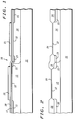
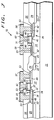
- FIGs. 1-7 illustrate enlarged cross-sectional views of a portion of an insulated gate field effect transistor during fabrication in accordance with an embodiment of the present invention.
- the present invention provides a semiconductor device such as an insulated gate field effect transistor and a method of fabricating or forming the transistor. More particularly, the method allows fabrication of an insulated gate field effect transistor having a channel region that is partially doped. This region is referred to as a partial channel and results in low subthreshold swings and higher saturation currents. Insulated gate field effect transistors having partial channels have an increased peak transconductance and saturation current compared to transistors having a full channel since the charge carriers in the partial channel have a high mobility. In addition, the partial channel lowers the source/drain capacitance.
- the channel is defined as the area in the semiconductor substrate between the source and drain regions that is under a gate structure and that is doped after the formation of the field oxide regions.
- the formation of the partial channel is accomplished by forming a thick gate structure and forming the partial channel in a portion of the semiconductor substrate covered by the thick gate structure.
- FIG. 1 illustrates an enlarged cross-sectional view of a portion of a partially completed low power insulated gate field effect transistor during processing in accordance with an embodiment of the present invention.
- a semiconductor substrate 11 of P-conductivity type having a major surface 12.
- An impurity well 13 of P ⁇ -conductivity type commonly referred to as a P-well, extends into semiconductor substrate 11 from a first portion of major surface 12 and an impurity well 14 of N ⁇ -conductivity type extends into substrate 11 from a second portion of major surface 12.
- P-well 13 laterally abuts N-well 14.
- a step 16 or bird's beak is formed after the formation of N-well 14 and before the formation of P-well 13.
- twin well processes are commonly referred to as twin well processes and typically result in the formation of bird's beaks 16.
- Twin well processes and bird's beak formation are well known to those skilled in the art.
- substrate 11 has a resistivity between approximately 6 ohm-centimeter ( ⁇ -cm) and approximately 8 ⁇ -cm
- wells 13 and 14 have a surface concentration on the order of 1 X 10¹⁶ atoms per cubic centimeter (atoms/cm3).
- a layer of oxide 17 is formed on major surface 12, a layer of polysilicon 18 is formed on oxide layer 17, and a layer of nitride (not shown) is formed on layer of polysilicon 18.
- the layer of nitride is patterned to form islands over active areas or regions in which transistors are to be fabricated. Although the layer of nitride is not shown, a first portion 19 of the nitride layer serves as one island and a second portion 21 serves as another island.
- layer of oxide 17, layer of polysilicon 18, and the layer of nitride form implant block masks over portions of wells 13 and 14. More particularly, first portion 19 serves as an implant block mask over a portion of P-well 13 and second portion 21 serves as an implant block mask over a portion of N-well 14.
- An additional implant block mask (not shown) of, for example, photoresist is formed over N-well 14.
- An impurity material of P conductivity type is implanted into portions of P-well 13 not protected by the implant block mask to form dopant regions 22.
- This implant block mask is removed and another implant block mask (not shown) of, for example, photoresist is formed over P-well 13 and dopant regions 22.
- An impurity material of N conductivity type is implanted into portions of N-well 14 not protected by the additional implant block mask to form dopant regions 23.
- Dopant regions 22 and 23 prevent inversion under field oxide regions 24 (shown in FIG. 2) and provide isolation punchthrough protection.
- FIG. 2 illustrates an enlarged cross-sectional view of the portion of the partially completed low power insulated gate field effect transistor of FIG. 1 further along in processing.
- the same reference numerals are used in the figures to denote the same elements.
- the concentrations and thicknesses provided in the description of the present invention merely serve as exemplary values and are not limitations of the present invention.
- An anneal is performed that forms field oxide regions 24 and drives in the impurity material of dopant regions 22 and 23, thereby enlarging dopant regions 22 and 23. Methods of forming dopant regions 22 and 23 are well known to those skilled in the art.
- Portions 19 and 21 of the nitride layer, polysilicon layer 18 and oxide layer 17 are removed using techniques well known to those skilled in the art.
- a layer of sacrificial oxide (not shown) is grown on major surface 12 and on field oxide regions 24.
- the sacrificial oxide layer has a thickness of approximately 400 angstroms.
- the sacrificial oxide layer serves to oxidize any silicon nitride film formed during field oxidation (Kooi effect) around the active region edges.
- the sacrificial oxide layer is removed and a layer of gate oxide 26 is formed on major surface 12 and on field oxide regions 24.
- gate oxide layer 26 has a thickness of approximately 105 angstroms.
- a layer of polysilicon 28 is formed on gate oxide layer 26.
- polysilicon layer 28 has a thickness of approximately 3,000 angstroms.
- Polysilicon layer 28 serves as a gate conductor layer.
- Methods for forming gate oxide layers such as gate oxide layer 26 and polysilicon layers such as polysilicon layer 28 are well known to those skilled in the art.
- the techniques used in preparation for the formation of gate oxide layer 26 and polysilicon layer 28, i.e., formation of a sacrificial oxide layer is also known in the semiconductor processing art.
- FIG. 4 illustrates an enlarged cross-sectional view of the portion of the partially completed low power insulated gate field effect transistor of FIG. 3 further along in processing.
- Layer of polysilicon 28 is patterned to form polysilicon gate electrodes 29 and 31 over P-well 13 and N-well 14, respectively.
- Gate electrodes 29 and 31 in conjunction with the portions of gate oxide layer 26 between major surface 12 and gate electrodes 29 and 31 form gate structures 29' and 31', respectively.
- An oxide layer 32 is formed on polysilicon gate electrodes 29 and 31. As those skilled in the art are aware, oxide layer 32 serves to re-grow the portions of gate oxide layer 26 that have been undercut.
- FIG. 5 illustrates an enlarged cross-sectional view of the portion of a partially completed complementary low power insulated gate field effect transistor 10.
- An implant block mask 33 of, for example, photoresist is formed on layer of oxide 32. Photoresist 33 is patterned to form a window 35 which exposes layer of oxide 32 over a portion of polysilicon gate electrode 29 and a portion of oxide layer 32 covering P-well 13. The exposed portion of oxide layer 32 covering P-well 13 is adjacent one side of polysilicon gate electrode 29.
- An impurity material of P conductivity type such as, for example, boron is implanted into a portion of P well 13 to form a dopant region 34.
- Dopant region 34 has a first portion 36 and a second portion 37.
- An implant energy for implanting the boron is selected such that the impurity material penetrates polysilicon gate electrode 29 and extends into P-well 13 to form second portion 37. Since the impurity material of second portion 37 must traverse or travel through the gate electrode 29, second portion 37 is shallower than first portion 36.
- a zero degree implant having an energy of approximately 100 Kilo-electron Volts (KeV) and a dose on the order of 1 x 10¹² atoms/cm2 results in a first region 36 having a surface concentration on the order of 1 x 10¹⁶ atoms/cm3 for polysilicon gate electrode 29 having a thickness of approximately 3,000 angstroms.
- first portion 36 extends approximately 0.5 micron ( ⁇ m) into P-well 13 from major surface 12 and second portion 37 has a surface concentration on the order of 1 x 10¹⁷ atoms/cm3 and extends approximately 0.2 ⁇ m into P-well 13 from major surface 12.
- a second zero degree boron implant is performed which does not penetrate gate electrode 29.
- the impurity material of the second zero degree implant does not enter second portion 37.
- this implant further dopes first portion 36 to provide punchthrough protection.
- the second implant has an energy of about 20 KeV, a dose on the order of 5 x 10¹³ atoms/cm2, and results in a surface concentration ranging between approximately 1 x 10¹⁸ atoms/cm3 and approximately 3 x 10¹⁸ atoms/cm3. These implant conditions result in a final junction depth of first portion 36 of approximately 0.6 ⁇ m.
- the optional second implant provides additional punchthrough protection.
- implant block mask 33 is removed and another implant block mask 38 of, for example, photoresist is formed on layer of oxide 32.
- Photoresist 38 is patterned to form a window 40 which exposes layer of oxide 32 over a portion of polysilicon gate electrode 31 and a portion of oxide layer 32 covering N-well 14.
- An impurity material of N conductivity type such as, for example, phosphorus is implanted into a portion of N-well 14 to form a dopant region 39.
- Dopant region 39 has a first portion 42 and a second portion 41.
- An implant energy for implanting the phosphorus is selected such that the impurity material penetrates polysilicon gate electrode 31 and extends into N-well 14 to form second portion 41. Since the impurity material of second portion 41 must traverse or travel through the gate electrode 31, second portion 41 is shallower than first portion 42.
- a zero degree implant having an energy of approximately 200 KeV and a dose on the order of 1 x 10¹² atoms/cm2 results in a first portion 42 having a surface concentration on the order of 1 x 10¹⁶ atoms/cm3 for polysilicon gate electrode 31 having a thickness of approximately 3,000 angstroms.
- first portion 42 extends approximately 0.5 ⁇ m into N-well 14 from major surface 12 and second portion 41 has a surface concentration on the order of 1 x 10¹⁷ atoms/cm3 and extends approximately 0.2 ⁇ m into N-well 14 from major surface 12.
- a second zero degree phosphorus implant is performed which does not penetrate gate electrode 31.
- the impurity material of the second zero degree implant does not enter second portion 41.
- this implant further dopes first portion 42 to provide punchthrough protection.
- the second implant has an energy of about 45 KeV, a dose on the order of 2 x 10¹³ atoms/cm2, and results in a surface concentration ranging between approximately 1 x 10¹⁸ atoms/cm3 and approximately 3 x 10¹⁸ atoms/cm3. These implant conditions result in a final junction depth of first portion 42 of approximately 0.6 ⁇ m.
- the optional second implant provides additional punchthrough protection.
- Implant block mask 38 is removed. Techniques for forming and removing implant block masks such as masks 33 and 38 are well known to those skilled in the art.
- FIG. 7 illustrates an enlarged cross-sectional view of the portion of the complementary low power insulated gate field effect transistor 10 of FIG. 6 further along in processing.
- Source and drain regions 48 and 49, respectively are formed in P-well 13 adjacent polysilicon gate electrode 29.
- Source and drain regions 48 and 49, respectively are of N conductivity type and formed using, for example by a zero degree arsenic implant.
- polysilicon gate electrode 29 is doped to be of N conductivity type, e.g., doped with arsenic.
- source and drain regions 51 and 52 are formed in N-well 14 adjacent polysilicon gate electrode 31.
- Source and drain regions 51 and 52 are of P conductivity type and formed using, for example, a zero degree boron implant.
- polysilicon gate electrode 31 is doped to be of P conductivity type, e.g., doped with boron.
- source region 51 is within dopant region 39.
- regions 48, 49, 51, and 52 extend between approximately 0.2 ⁇ m and approximately 0.3 ⁇ m into their respective wells 13 and 14 from major surface 12.
- the dopant concentration ranges between approximately 5 x 10¹⁶ atoms/cm3 and 1 x 10¹⁸ atoms/cm3.
- source regions 48 and 51 be contained within dopant regions 34 and 39, respectively, it shall be understood that alternatively drain regions 49 and 52 are contained within dopant regions 34 and 39, respectively, or a source region is contained within a dopant region and a drain region is contained within another dopant region.
- Methods of forming source and drain regions such as regions 48, 49, 51, and 52 are well known to those skilled in the art.
- An oxide layer (not shown) is formed on oxide layer 32. The oxide layer has a thickness on the order of 300 angstroms and may be formed by well known processes such as a tetraethylorthosilicate (TEOS) deposition process.
- TEOS tetraethylorthosilicate
- dielectric spacers 46 are formed along oxide layer 32 lining the sidewalls of polysilicon gate electrodes 29 and 31.
- spacers 46 are nitride spacers. It shall be understood that dielectric spacers 46 are optional.
- electrodes are formed which contact regions 48, 49, 51, and 52, as well as gate electrodes 29 and 31.
- a silicide 53 may be formed in source regions 48 and 51, drain regions 49 and 52 and in polysilicon gate electrodes 29 and 31.
- An insulating layer 54 is formed on device 10, i.e., on field oxide regions 24, source regions 48 and 51, drain regions 49 and 52, and polysilicon gate electrodes 29 and 31.
- a plurality of openings are formed in insulating layer 54 to expose portions of silicide 53 in source regions 48 and 51, drain regions 49 and 52, and polysilicon gate electrodes 29 and 31.
- Source and drain electrodes 56 and 57 are formed to contact the silicide 53 in the respective source and drain regions 48 and 49.
- Source and drain electrodes 58 and 59 are formed to contact the silicide 53 in the respective source and drain regions 51 and 52,
- Gate electrodes 61 and 62 are formed to contact the silicide on polysilicon gate electrodes 29 and 31, respectively. Methods of forming electrodes to silicided regions are well known to those skilled in the art.
- the present invention comprises a method for fabricating complementary insulated gate semiconductor device 10 having source regions 48 and 51, drain regions 49 and 52, and gate electrodes 29 and 31.
- a complementary low power insulated gate semiconductor device 10 having a partial channel has been described, it shall be understood that individual N-channel and P-channel insulated gate semiconductor devices having partial channels may also be fabricated in accordance with the present invention.
- the partial channel is formed by masking a high energy implant through part of the gate electrode. Since these devices have less dopants in the non-implanted channel region, the dopant has a high mobility resulting in high peak transconductance and saturation current. In addition, both these devices have a low body effect, due to the light doping of the wells used in the process, as well as high saturation currents. The low body effect allows for stacking of devices. Further, these devices have subthreshold swings in the range of 70-80 mV/decade of drain current. These low subthreshold swings permit lowering of the threshold voltage without compromising the leakage current, which is highly desirable for low power and low voltage applications.
Landscapes
- Metal-Oxide And Bipolar Metal-Oxide Semiconductor Integrated Circuits (AREA)
- Insulated Gate Type Field-Effect Transistor (AREA)
Applications Claiming Priority (2)
| Application Number | Priority Date | Filing Date | Title |
|---|---|---|---|
| US223398 | 1981-01-08 | ||
| US08/223,398 US5441906A (en) | 1994-04-04 | 1994-04-04 | Insulated gate field effect transistor having a partial channel and method for fabricating |
Publications (2)
| Publication Number | Publication Date |
|---|---|
| EP0676798A2 true EP0676798A2 (de) | 1995-10-11 |
| EP0676798A3 EP0676798A3 (de) | 1996-07-17 |
Family
ID=22836321
Family Applications (1)
| Application Number | Title | Priority Date | Filing Date |
|---|---|---|---|
| EP95104910A Withdrawn EP0676798A3 (de) | 1994-04-04 | 1995-04-03 | Feldeffekttransistor mit isoliertem Gate und asymmetrischem Kanal und Verfahren zur Herstellung. |
Country Status (4)
| Country | Link |
|---|---|
| US (1) | US5441906A (de) |
| EP (1) | EP0676798A3 (de) |
| JP (1) | JPH07283412A (de) |
| KR (1) | KR950034769A (de) |
Cited By (1)
| Publication number | Priority date | Publication date | Assignee | Title |
|---|---|---|---|---|
| US6611680B2 (en) | 1997-02-05 | 2003-08-26 | Telefonaktiebolaget Lm Ericsson (Publ) | Radio architecture |
Families Citing this family (18)
| Publication number | Priority date | Publication date | Assignee | Title |
|---|---|---|---|---|
| US5744372A (en) * | 1995-04-12 | 1998-04-28 | National Semiconductor Corporation | Fabrication of complementary field-effect transistors each having multi-part channel |
| KR960042942A (ko) * | 1995-05-04 | 1996-12-21 | 빈센트 비.인그라시아 | 반도체 디바이스 형성 방법 |
| EP0789401A3 (de) * | 1995-08-25 | 1998-09-16 | Matsushita Electric Industrial Co., Ltd. | LD-MOSFET oder MOSFET mit einer diese enthaltenden integrierten Schaltung und Verfahren zur Herstellung |
| US5716866A (en) * | 1995-08-30 | 1998-02-10 | Motorola, Inc. | Method of forming a semiconductor device |
| US6127700A (en) * | 1995-09-12 | 2000-10-03 | National Semiconductor Corporation | Field-effect transistor having local threshold-adjust doping |
| US5736440A (en) * | 1995-11-27 | 1998-04-07 | Micron Technology, Inc. | Semiconductor processing method of forming complementary NMOS and PMOS field effect transistors on a substrate |
| US5681761A (en) * | 1995-12-28 | 1997-10-28 | Philips Electronics North America Corporation | Microwave power SOI-MOSFET with high conductivity metal gate |
| US5719425A (en) * | 1996-01-31 | 1998-02-17 | Micron Technology, Inc. | Multiple implant lightly doped drain (MILDD) field effect transistor |
| US5817561A (en) * | 1996-09-30 | 1998-10-06 | Motorola, Inc. | Insulated gate semiconductor device and method of manufacture |
| US5811341A (en) * | 1996-12-09 | 1998-09-22 | Motorola, Inc. | Differential amplifier having unilateral field effect transistors and process of fabricating |
| US6027978A (en) * | 1997-01-28 | 2000-02-22 | Advanced Micro Devices, Inc. | Method of making an IGFET with a non-uniform lateral doping profile in the channel region |
| JPH10242419A (ja) * | 1997-02-27 | 1998-09-11 | Mitsubishi Electric Corp | 半導体装置の製造方法及び半導体装置 |
| US5998274A (en) * | 1997-04-10 | 1999-12-07 | Micron Technology, Inc. | Method of forming a multiple implant lightly doped drain (MILDD) field effect transistor |
| US6306763B1 (en) * | 1997-07-18 | 2001-10-23 | Advanced Micro Devices, Inc. | Enhanced salicidation technique |
| KR100236098B1 (ko) | 1997-09-06 | 1999-12-15 | 김영환 | 반도체소자 및 그 제조방법 |
| US5904517A (en) * | 1998-07-08 | 1999-05-18 | Advanced Micro Devices, Inc. | Ultra thin high K spacer material for use in transistor fabrication |
| EP1011137A1 (de) | 1998-12-16 | 2000-06-21 | STMicroelectronics S.r.l. | Verfahren zum Integrieren von Widerständen und ESD-Selbstschutz-Transistoren mit Speichermatrix |
| TWI543358B (zh) * | 2014-01-13 | 2016-07-21 | 友達光電股份有限公司 | 顯示面板的畫素 |
Family Cites Families (14)
| Publication number | Priority date | Publication date | Assignee | Title |
|---|---|---|---|---|
| US4062699A (en) * | 1976-02-20 | 1977-12-13 | Western Digital Corporation | Method for fabricating diffusion self-aligned short channel MOS device |
| US5024960A (en) * | 1987-06-16 | 1991-06-18 | Texas Instruments Incorporated | Dual LDD submicron CMOS process for making low and high voltage transistors with common gate |
| IT1223571B (it) * | 1987-12-21 | 1990-09-19 | Sgs Thomson Microelectronics | Procedimento per la fabbricazione di dispositivi integrati cmos con lunghezze di porta ridotte |
| JP2666403B2 (ja) * | 1988-01-06 | 1997-10-22 | セイコーエプソン株式会社 | Mis型半導体装置の製造方法 |
| US4949136A (en) * | 1988-06-09 | 1990-08-14 | University Of Connecticut | Submicron lightly doped field effect transistors |
| US5258635A (en) * | 1988-09-06 | 1993-11-02 | Kabushiki Kaisha Toshiba | MOS-type semiconductor integrated circuit device |
| US4898835A (en) * | 1988-10-12 | 1990-02-06 | Sgs-Thomson Microelectronics, Inc. | Single mask totally self-aligned power MOSFET cell fabrication process |
| KR940010930B1 (ko) * | 1990-03-13 | 1994-11-19 | 가부시키가이샤 도시바 | 반도체장치의 제조방법 |
| US5202276A (en) * | 1990-08-20 | 1993-04-13 | Texas Instruments Incorporated | Method of forming a low on-resistance DMOS vertical transistor structure |
| US5166087A (en) * | 1991-01-16 | 1992-11-24 | Sharp Kabushiki Kaisha | Method of fabricating semiconductor element having lightly doped drain (ldd) without using sidewalls |
| US5162884A (en) * | 1991-03-27 | 1992-11-10 | Sgs-Thomson Microelectronics, Inc. | Insulated gate field-effect transistor with gate-drain overlap and method of making the same |
| US5171700A (en) * | 1991-04-01 | 1992-12-15 | Sgs-Thomson Microelectronics, Inc. | Field effect transistor structure and method |
| US5182619A (en) * | 1991-09-03 | 1993-01-26 | Motorola, Inc. | Semiconductor device having an MOS transistor with overlapped and elevated source and drain |
| US5248627A (en) * | 1992-03-20 | 1993-09-28 | Siliconix Incorporated | Threshold adjustment in fabricating vertical dmos devices |
-
1994
- 1994-04-04 US US08/223,398 patent/US5441906A/en not_active Expired - Fee Related
-
1995
- 1995-03-29 KR KR1019950006815A patent/KR950034769A/ko not_active Withdrawn
- 1995-03-29 JP JP7094221A patent/JPH07283412A/ja active Pending
- 1995-04-03 EP EP95104910A patent/EP0676798A3/de not_active Withdrawn
Cited By (2)
| Publication number | Priority date | Publication date | Assignee | Title |
|---|---|---|---|---|
| US6611680B2 (en) | 1997-02-05 | 2003-08-26 | Telefonaktiebolaget Lm Ericsson (Publ) | Radio architecture |
| US6973290B2 (en) | 1997-02-05 | 2005-12-06 | Telefonaktiebolaget L M Ericsson (Publ) | Radio architecture |
Also Published As
| Publication number | Publication date |
|---|---|
| JPH07283412A (ja) | 1995-10-27 |
| EP0676798A3 (de) | 1996-07-17 |
| KR950034769A (ko) | 1995-12-28 |
| US5441906A (en) | 1995-08-15 |
Similar Documents
| Publication | Publication Date | Title |
|---|---|---|
| US5427964A (en) | Insulated gate field effect transistor and method for fabricating | |
| US5482878A (en) | Method for fabricating insulated gate field effect transistor having subthreshold swing | |
| EP0749165B1 (de) | Dünnfilmtransistor über einem isolierten Halbleitersubstrat und Verfahren zur Herstellung | |
| US5359219A (en) | Silicon on insulator device comprising improved substrate doping | |
| US6100143A (en) | Method of making a depleted poly-silicon edged MOSFET structure | |
| US5441906A (en) | Insulated gate field effect transistor having a partial channel and method for fabricating | |
| US6548874B1 (en) | Higher voltage transistors for sub micron CMOS processes | |
| US6277675B1 (en) | Method of fabricating high voltage MOS device | |
| KR900000072B1 (ko) | 협채널 폭을 갖는 절연게이트형 fet의 제조방법 | |
| US6514810B1 (en) | Buried channel PMOS transistor in dual gate CMOS with reduced masking steps | |
| JPH04255266A (ja) | Mosトランジスタを半導体ウエハ上にvlsi構造に形成するための改良された方法 | |
| EP1026738A2 (de) | Verfahren mit reduzierter Maskenzahl für die Herstellung von Mischsspannung-CMOS mit Hochleistung-Transistoren und -I/O Transistoren von hoher Zuverlässigkeit | |
| US20030127694A1 (en) | Higher voltage transistors for sub micron CMOS processes | |
| US6583013B1 (en) | Method for forming a mixed voltage circuit having complementary devices | |
| US5786265A (en) | Methods of forming integrated semiconductor devices having improved channel-stop regions therein, and devices formed thereby | |
| US6586296B1 (en) | Method of doping wells, channels, and gates of dual gate CMOS technology with reduced number of masks | |
| US6001677A (en) | Method for fabricating CMOS transistors by implanting into polysilicon | |
| US6303420B1 (en) | Integrated bipolar junction transistor for mixed signal circuits | |
| US5918117A (en) | Method for manufacturing semiconductor device having an ESD protection region | |
| JPH0730107A (ja) | 高耐圧トランジスタ及びその製造方法 | |
| JPH08186179A (ja) | 相補型半導体装置 | |
| US6667524B1 (en) | Semiconductor device with a plurality of semiconductor elements | |
| JPH10135349A (ja) | Cmos型半導体装置及びその製造方法 | |
| US7560779B2 (en) | Method for forming a mixed voltage circuit having complementary devices | |
| KR100281397B1 (ko) | 초박형 soi 정전기방전 보호 소자의 형성 방법 |
Legal Events
| Date | Code | Title | Description |
|---|---|---|---|
| PUAI | Public reference made under article 153(3) epc to a published international application that has entered the european phase |
Free format text: ORIGINAL CODE: 0009012 |
|
| AK | Designated contracting states |
Kind code of ref document: A2 Designated state(s): DE FR GB |
|
| PUAL | Search report despatched |
Free format text: ORIGINAL CODE: 0009013 |
|
| AK | Designated contracting states |
Kind code of ref document: A3 Designated state(s): DE FR GB |
|
| 17P | Request for examination filed |
Effective date: 19970117 |
|
| 17Q | First examination report despatched |
Effective date: 19990129 |
|
| STAA | Information on the status of an ep patent application or granted ep patent |
Free format text: STATUS: THE APPLICATION IS DEEMED TO BE WITHDRAWN |
|
| 18D | Application deemed to be withdrawn |
Effective date: 19990609 |