EP0677329A1 - Broyeur annulaire à boulets - Google Patents
Broyeur annulaire à boulets Download PDFInfo
- Publication number
- EP0677329A1 EP0677329A1 EP95105381A EP95105381A EP0677329A1 EP 0677329 A1 EP0677329 A1 EP 0677329A1 EP 95105381 A EP95105381 A EP 95105381A EP 95105381 A EP95105381 A EP 95105381A EP 0677329 A1 EP0677329 A1 EP 0677329A1
- Authority
- EP
- European Patent Office
- Prior art keywords
- grinding
- ball
- mill
- force
- force application
- Prior art date
- Legal status (The legal status is an assumption and is not a legal conclusion. Google has not performed a legal analysis and makes no representation as to the accuracy of the status listed.)
- Withdrawn
Links
Images


Classifications
-
- B—PERFORMING OPERATIONS; TRANSPORTING
- B02—CRUSHING, PULVERISING, OR DISINTEGRATING; PREPARATORY TREATMENT OF GRAIN FOR MILLING
- B02C—CRUSHING, PULVERISING, OR DISINTEGRATING IN GENERAL; MILLING GRAIN
- B02C15/00—Disintegrating by milling members in the form of rollers or balls co-operating with rings or discs
- B02C15/12—Mills with at least two discs or rings and interposed balls or rollers mounted like ball or roller bearings
Definitions
- the invention relates to a ball ring mill with a mill housing, a grinding track and grinding balls, which are acted upon by an external force and run on the grinding track and comminute the ground material.
- the grinding track is formed by a lower driven grinding ring, on which the grinding balls run. These, in turn, are pressed against the grinding path by an upper grinding ring which is acted upon by an external force generated in a special device (generally a spring or hydraulic device).
- a special device generally a spring or hydraulic device.
- Ball ring mills are used in particular for coal grinding in coal dust furnaces and for gypsum grinding in the production of gypsum. They are subject to considerable wear during operation, which is caused both by the removal of material from the moving parts of the mill and by material fatigue in the parts of the mill which do not directly participate in the actual grinding process.
- the invention has for its object to provide a ball ring mill of the type mentioned, in which the grinding set (parts that are either directly involved in the grinding process or are used to transfer the grinding force and / or the torque to the immediately grinding parts), has a longer service life than previously known mills and which also reduces wear on the other parts of the mill due to material fatigue.
- the invention solves this problem in a ball ring mill according to the preamble of the main claim in that a separate pressure device for transmitting the external force to this grinding ball is provided for each grinding ball.
- the invention has recognized that the one-piece upper grinding ring used in the prior art, which presses the grinding balls onto the grinding track, is disadvantageous in several respects. Disturbances in the grinding process, for example the rolling over of a hard foreign body by a single grinding ball, simultaneously influence all other grinding balls via this one-piece upper grinding ring. This can lead to undesirable vibration excitation, especially in the range of the natural frequencies of many mill parts, so that resonances can occur which can lead to fatigue and destruction of the mill structure. In the mill according to the invention, however, because of the separate pressing device for each grinding ball, the balls are guided individually and are thus decoupled from one another to a greater extent than in the prior art, disturbances in the course of a ball cannot be transferred or to a lesser extent to the other grinding balls.
- Each pressure device expediently has a spherical cap surface as a pressure surface acting on the grinding ball.
- a spherical cap surface as a pressure surface acting on the grinding ball.
- Each pressure device can be connected to a common force application member.
- This common force application element can be designed, for example, as a shaft which is acted upon by the external force and is arranged centrally with respect to the axis of rotation of the mill. This shaft is then acted upon by the external force in the area of the mill foundation, for example, and guides it via rigidly connected to it Arms into each pressure device.
- each force application member applies the grinding force to the associated grinding ball completely independently of the other force application members and grinding balls and is accordingly also connected to its own external power source.
- the grinding balls run largely independently of one another, so that mutual interference in the event of faults such as rolling over foreign bodies is almost completely ruled out.
- each force application member can be designed as an arm connected to the respective pressing device, which is articulated on a shaft arranged centrally with respect to the axis of rotation of the mill.
- Each arm is then connected to its own external power source, for example a spring device, and thus applies the grinding force to the associated pressure device.
- the centrally arranged shaft itself no longer serves as a force application element, but merely as an abutment for deriving the grinding force into the mill housing.
- each force application member is designed as a toggle lever which is acted upon by the external force and which is articulated on the pressure device and on the mill housing.
- a compression spring arranged between the mill housing and the toggle lever can be provided as the external power source.
- the area of the mill housing in which the toggle levers are articulated generally the housing area surrounding the grinding chamber, must be designed to be sufficiently stable to be able to absorb and derive the grinding force as an abutment.
- the pressure devices have spherical cap surfaces as pressure surfaces acting on the grinding balls, there is a rubbing movement between the grinding balls and the pressure devices during the grinding process. So that the wear caused by this friction of grinding balls and Pressure devices remains low, a lubrication that reduces this friction is expediently provided. Under certain circumstances, the dust corresponding to the grinding process can serve as a lubricant. However, it is advantageous if lubrication devices are provided for injecting a special lubricant between the contact surfaces of balls and pressure devices. For example, coal, water or a coal-water dispersion can serve as a lubricant. Instead of coal, another solid to be ground can also be used as a lubricant. Liquid lubricants are injected by means of a high-pressure pump through a corresponding opening in the pressure devices.
- the pressure devices can be stationary in relation to the mill housing in grinding operation. However, it is also conceivable to design the pressure devices to be rotatable about the grinding axis. For this purpose, for example in the above-described embodiments with a central shaft, this shaft can be provided with drive devices by means of which it can be set into a rotary movement.
- Embodiments of the invention have been mentioned above, in which either a common force application element for all pressure devices or separate force application elements are provided for each individual pressure device. Intermediate solutions are also conceivable within the scope of the invention, in which one force application member acts on the plurality, but not all, of the separate pressure devices with the grinding force.
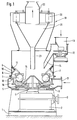
- a gear 2 is arranged in the foundation 1 of the ball ring mill, to which drive power is supplied via the clutch 3.
- the transmission 2 has a vertical output hub 4, which is mounted in the transmission 2 in an axial pressure bearing, which receives the grinding pressure.
- This hub 4 is integrally connected to a turntable 5 on which the lower grinding ring 6 is mounted and connected to it in a rotationally fixed manner.
- Rolling balls 7 roll on the lower grinding ring 6, each of which is pressed against the lower grinding ring 6 by a separate pressure device 8.
- the pressure devices 8 have a spherical cap surface facing the lower grinding ring 6 as the pressure surface for the grinding balls 7.
- a toggle lever 9 is articulated to each pressure device 8, which in turn is articulated at 10 to the mill housing.
- each grinding ball 7 is acted upon by the grinding force by a separate pressure device 8, toggle lever 9 and compression spring 11.
- devices can be provided in the drawing which press lubricant between these contact surfaces.
- the compression springs 11 are not supported directly on the mill housing, but on a hydraulic device, not shown in the drawing, by means of which the spring preload and thus the grinding force can be adjusted.
- regrind is fed to the grinding chamber 15 via a task 13 provided with a plate feeder 12 and through a nozzle 14.
- the ground material which is introduced approximately in the center of the grinding chamber 15, is ground between the lower grinding ring 6 and the grinding balls 7 and, due to the centrifugal effect of the rotating lower grinding ring 6, is carried outwards.
- the lower grinding ring 6 is surrounded by an annular space 16 which is fed with air via a nozzle 17.
- the air is blown upwards at high speed through an annular gap 18 and takes the ground material with it to the air classifier 19.
- the ground material is guided past the control flaps 20 into the funnel 21 of the air classifier. Sufficiently ground ground material is discharged through the nozzle 22 with the outflowing air.
- the desired fineness can be adjusted by adjusting the control flaps 20. If, during operation of the mill, the run of a grinding ball 7 is disturbed, for example, by rolling over foreign bodies, the running of the remaining grinding balls 7 is not affected by this disturbance. It will therefore, neither forces occurring due to the foreign body rollover are transferred to the other grinding balls, nor is there any mutual interference in the sense of undesirable vibration excitation.
- the mill housing does not directly serve as an abutment for the grinding force, rather an additional shaft 24 is provided which is arranged centrally with respect to the axis of rotation of the mill and is mounted in the gear 2 so that it has tensile forces can record.
- the shaft 24 can be freely rotated relative to the hub 4, the turntable 5 and the lower grinding ring 6, and it can optionally have its own drive device. Under certain circumstances, the shaft 24 can also be arranged in a stationary manner with respect to the mill housing. In no case is it non-rotatably connected to the hub 4, the turntable 5 and the lower grinding ring 6.
- Arms or levers 26 are articulated at 25 at the tip of the shaft 24, each of which is articulated at 27 to a pressure device 8.
- Each lever 26 is spring-loaded by means of a tension spring 28 arranged between this lever and the shaft 24, it transmits this spring force to the associated pressure device 8 and thus to the respective grinding ball 7.
- a shaft 29 is provided which is arranged centrally with respect to its axis of rotation and which, like the shaft 24 of the embodiment shown in FIG. It can also be driven or possibly also stationary with respect to the mill housing.
- the shaft 29 does not serve as an abutment for absorbing the grinding force, but rather as the actual force application element; it is acted upon in the transmission 2 by a device (not shown) (for example a spring or hydraulic device) with the external force or grinding force.
- the shaft 29 is rigidly connected to arms 30, which each lead to the pressure devices 8 and thus apply the grinding force to them.
- the shaft 29 is thus subjected to the entire grinding force for all grinding balls; this grinding force is distributed via the arms 30 to the respective pressure devices 8 and thus to the grinding balls 7.
Landscapes
- Engineering & Computer Science (AREA)
- Food Science & Technology (AREA)
- Crushing And Grinding (AREA)
- Electrochromic Elements, Electrophoresis, Or Variable Reflection Or Absorption Elements (AREA)
- Disintegrating Or Milling (AREA)
Applications Claiming Priority (2)
| Application Number | Priority Date | Filing Date | Title |
|---|---|---|---|
| DE9406144U DE9406144U1 (de) | 1994-04-13 | 1994-04-13 | Kugelringmühle |
| DE9406144U | 1994-04-13 |
Publications (1)
| Publication Number | Publication Date |
|---|---|
| EP0677329A1 true EP0677329A1 (fr) | 1995-10-18 |
Family
ID=6907275
Family Applications (1)
| Application Number | Title | Priority Date | Filing Date |
|---|---|---|---|
| EP95105381A Withdrawn EP0677329A1 (fr) | 1994-04-13 | 1995-04-10 | Broyeur annulaire à boulets |
Country Status (4)
| Country | Link |
|---|---|
| EP (1) | EP0677329A1 (fr) |
| DE (1) | DE9406144U1 (fr) |
| FI (1) | FI951754L (fr) |
| PL (1) | PL176560B1 (fr) |
Cited By (4)
| Publication number | Priority date | Publication date | Assignee | Title |
|---|---|---|---|---|
| CN107051681A (zh) * | 2017-05-28 | 2017-08-18 | 宋双燕 | 一种高效的中药研磨装置 |
| CN108161015A (zh) * | 2016-08-25 | 2018-06-15 | 梁怡芃 | 一种粉碎装置 |
| CN109622577A (zh) * | 2019-02-01 | 2019-04-16 | 南昌见诚科技有限公司 | 一种安全性能高的电子产品回收破碎设备 |
| CN118371302A (zh) * | 2024-06-21 | 2024-07-23 | 江苏爱矽半导体科技有限公司 | 一种半导体微硅粉的研磨制备装置 |
Citations (5)
| Publication number | Priority date | Publication date | Assignee | Title |
|---|---|---|---|---|
| US1332850A (en) * | 1916-10-10 | 1920-03-02 | Kutsche Oswald | Comminuting apparatus |
| DE499699C (de) * | 1926-10-23 | 1930-06-11 | Hermann Hildebrandt | Mahlvorrichtung mit gegen eine Mahlbahn gedrueckten Mahlkoerpern |
| US2253819A (en) * | 1938-04-26 | 1941-08-26 | Harold V Spaulding | Ring and ball mill |
| FR2299912A1 (fr) * | 1975-02-07 | 1976-09-03 | Fives Cail Babcock | Perfectionnements au traitement des boues en vue de la production de materiaux en fines particule |
| DE2918195A1 (de) * | 1979-05-05 | 1980-11-06 | Peters Ag Claudius | Muehle mit mahl-waelzkoerpern zwischen einer oberen und einer unteren mahlringeinheit |
-
1994
- 1994-04-13 DE DE9406144U patent/DE9406144U1/de not_active Expired - Lifetime
-
1995
- 1995-04-10 EP EP95105381A patent/EP0677329A1/fr not_active Withdrawn
- 1995-04-11 PL PL95308077A patent/PL176560B1/pl unknown
- 1995-04-12 FI FI951754A patent/FI951754L/fi unknown
Patent Citations (5)
| Publication number | Priority date | Publication date | Assignee | Title |
|---|---|---|---|---|
| US1332850A (en) * | 1916-10-10 | 1920-03-02 | Kutsche Oswald | Comminuting apparatus |
| DE499699C (de) * | 1926-10-23 | 1930-06-11 | Hermann Hildebrandt | Mahlvorrichtung mit gegen eine Mahlbahn gedrueckten Mahlkoerpern |
| US2253819A (en) * | 1938-04-26 | 1941-08-26 | Harold V Spaulding | Ring and ball mill |
| FR2299912A1 (fr) * | 1975-02-07 | 1976-09-03 | Fives Cail Babcock | Perfectionnements au traitement des boues en vue de la production de materiaux en fines particule |
| DE2918195A1 (de) * | 1979-05-05 | 1980-11-06 | Peters Ag Claudius | Muehle mit mahl-waelzkoerpern zwischen einer oberen und einer unteren mahlringeinheit |
Cited By (5)
| Publication number | Priority date | Publication date | Assignee | Title |
|---|---|---|---|---|
| CN108161015A (zh) * | 2016-08-25 | 2018-06-15 | 梁怡芃 | 一种粉碎装置 |
| CN107051681A (zh) * | 2017-05-28 | 2017-08-18 | 宋双燕 | 一种高效的中药研磨装置 |
| CN109622577A (zh) * | 2019-02-01 | 2019-04-16 | 南昌见诚科技有限公司 | 一种安全性能高的电子产品回收破碎设备 |
| CN109622577B (zh) * | 2019-02-01 | 2023-06-16 | 南昌见诚科技有限公司 | 一种安全性能高的电子产品回收破碎设备 |
| CN118371302A (zh) * | 2024-06-21 | 2024-07-23 | 江苏爱矽半导体科技有限公司 | 一种半导体微硅粉的研磨制备装置 |
Also Published As
| Publication number | Publication date |
|---|---|
| PL308077A1 (en) | 1995-10-16 |
| PL176560B1 (pl) | 1999-06-30 |
| DE9406144U1 (de) | 1995-08-10 |
| FI951754A7 (fi) | 1995-10-14 |
| FI951754L (fi) | 1995-10-14 |
| FI951754A0 (fi) | 1995-04-12 |
Similar Documents
| Publication | Publication Date | Title |
|---|---|---|
| DE3921986C1 (fr) | ||
| CH627951A5 (de) | Walzenstuhl fuer die schrotung und vermahlung von getreide. | |
| DE4418139C1 (de) | Mahlwerk für Kaffeemühlen | |
| DE3815218A1 (de) | Luftstrom-mahlanlage | |
| DE2730166A1 (de) | Verfahren fuer die vermahlung von getreide und vorrichtung zur durchfuehrung des verfahrens | |
| DE102007041878B4 (de) | Verfahren und Rollenmühle zur Zerkleinerung von Mahlgut | |
| EP3129148B1 (fr) | Fixation de l'axe dans un concasseur à cône | |
| EP0294609A2 (fr) | Broyeur à rouleaux | |
| EP2271429B1 (fr) | Broyeur à cylindre | |
| DE3602932A1 (de) | Verfahren und vorrichtung zum zerkleinern von feststoffen | |
| EP0677329A1 (fr) | Broyeur annulaire à boulets | |
| DE3037670A1 (de) | Walzenbrecher | |
| DE4140549A1 (de) | Walzenmuehle | |
| DE1163121B (de) | Kugelquetschmuehle | |
| DE3330586A1 (de) | Waelzlagerung fuer einen kegelbrecher | |
| DE6947529U (de) | Fliehkraftringrollenmuehle. | |
| DE106932C (fr) | ||
| DE2552268C3 (fr) | ||
| EP0230943A1 (fr) | Dispositif pour le bobinage d'un fil | |
| WO2018234167A1 (fr) | Dispositif de traitement de fibres | |
| DE698991C (de) | Reibscheibenmahlmaschine | |
| DE654806C (de) | Kugelmuehle | |
| DE3231526A1 (de) | Verbesserter windsichter | |
| DE1278199B (de) | Kreiselbrecher mit geringer Einbauhoehe | |
| DE2912636A1 (de) | Zwei- und mehrreihige kugelringmuehle |
Legal Events
| Date | Code | Title | Description |
|---|---|---|---|
| PUAI | Public reference made under article 153(3) epc to a published international application that has entered the european phase |
Free format text: ORIGINAL CODE: 0009012 |
|
| AK | Designated contracting states |
Kind code of ref document: A1 Designated state(s): DE FR GB IT SE |
|
| 17P | Request for examination filed |
Effective date: 19960404 |
|
| 17Q | First examination report despatched |
Effective date: 19980820 |
|
| GRAG | Despatch of communication of intention to grant |
Free format text: ORIGINAL CODE: EPIDOS AGRA |
|
| RAP1 | Party data changed (applicant data changed or rights of an application transferred) |
Owner name: BMH CLAUDIUS PETERS GMBH |
|
| GRAG | Despatch of communication of intention to grant |
Free format text: ORIGINAL CODE: EPIDOS AGRA |
|
| GRAH | Despatch of communication of intention to grant a patent |
Free format text: ORIGINAL CODE: EPIDOS IGRA |
|
| GRAH | Despatch of communication of intention to grant a patent |
Free format text: ORIGINAL CODE: EPIDOS IGRA |
|
| STAA | Information on the status of an ep patent application or granted ep patent |
Free format text: STATUS: THE APPLICATION IS DEEMED TO BE WITHDRAWN |
|
| 18D | Application deemed to be withdrawn |
Effective date: 20011101 |